
Statistics
We looked inside some of the posts by rocampbell27 and here's what we found interesting.
Average Info
Notes Per Post
1
Likes Per Post
1
Reblog Per Post
0
Reply Per Post
0
Time Between Posts
3 months
Number of Posts By Type
Video
1
Photo
3
Text
1
Last Seen Tumblr Blogs


Fun Fact
Women make up for the other 50% of Tumblr’s audience.
Video
youtube
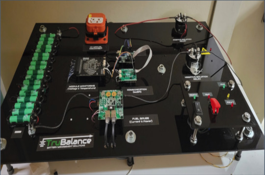
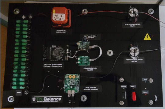
Senior Design: Designed and built a prototype battery and battery management system (BMS) for UIC Motorsports' 1st generation SAE Formula E car.
1 note
·
View note

Photo

8-Bit, mono source, line level audio recorder
youtube
0 notes
Text
Introduction:
The purpose of this project is to create a line level audio recorder using the Tiva C Launchpad. The analog source will be converted to a binary digital signal using the onboard 12-bit ADC with differential input. Audio will be sampled at 44.1 KHz to allow for full audio band capture and reproduction in observance of the Nyquist-Shannon Theorem. In order to efficiently clock the ADC I am using a timer configured to the appropriate sampling period. An interrupt handler will be used to control retrieval of the sampled data from the FIFO. The sampled information will be transferred through UART serial communication to a program running on a personal computer. This program will be used to compile that data into a PCM audio file readable by a DAW called Audacity.
The line level audio recorder was designed using the Texas Instruments TMC4C123G, I will refer to this as TI throughout the report. Programming was performed in Code Composer Studio and data was sent from the controller to a PC using serial communication (via USB) to an external terminal called Serial. From there I was able to import the produced raw data to Audacity for playback and analysis.
To start, my source was a line level audio signal fed from a soundcard output through a mono unbalanced quarter inch cable. The incoming audio signal had maximum amplitude of +/- 1.2 volts in order to stay within the bounds of the differential input specifications.
The TI has a reference voltage of 3.3 V but when using the ADC to sample in the differential configuration it requires the signal to be halved to allow for both positive and negative values. The ring of the cable (Vin-) was fed directly to pin PE3 of the TI and the tip (Vin+) was fed to PE2. These pins were configured as GPIOPinTypeADC.
Setting up the ADC for differential sampling requires adding a D to the step’s configuration nibble. In this case I chose ADC sampler 0 and used differential pair zero in accordance with my pin selections. Also, configured here was an interrupt when the sample sequence was finished and stored in the FIFO.
Once the interrupt was set, the interrupt handler was used to clear the interrupt, copy the 12-bit sample from FIFO to an unsigned 32 bit variable (adcValue), and set a boolean condition to be used later for the serial communication.
Configuration of the interrupt handler required adding the function to the vector table located in the startup file.
The TI has a clock rate of 50 MHz. In order to clock the ADC for 44.1KHz sampling I chose to use the timer module. The timer was set to the sampling period required. In this case, 50 MHz / 44.1KHz. This sampling period allows for reproduction of frequencies between 20 Hz and 20 KHz in accordance with the Nyquist Theorem. With this sampling rate we now generate 44,100 samples per second, each with a resolution of 12 bits. (for reference, CD quality audio is 44.1 KHz/16 bit)
One issue in generating the PCM file was that PCM audio read by Audacity must adhere to a particular format, that format being 8 bit unsigned. The samples I produced with the TI are unsigned 32 bit integers holding 12 bits of sample data, so I had to truncate adcValue after shifting right by 4 bits. These truncated 8 bit values were then sent via USB to the external terminal Serial.
Communication was done through UART on the TI with a baud rate of 115200 which was the max allowable in Serial. This seems to produce a sped up file when played back, but adjusting the playback speed reveals a very accurate data transfer. A call to uartPutChar, included in utility, was made with the argument being the 8 bit truncated values (char bitAdcValue). The call was allowed only when the boolean set by the ADC interrupt handler was true.
Serial allows for each session to be automatically logged and saved using binary data format. One of the most difficult things was trying to visually determine if the values being produced made logical sense. When using a standard DC voltage as the input of the ADC we expect to see lower values when the signal is at a minimum. This didn’t prove to be true with differential input. In my case, the quietest signal was represented by a decimal value of approximately 2045 and normal fluctuations of the input signal didn’t cause large fluctuations in the data. I found that full signal representation swung between approximately 1850 and 2045 with no clipping. Visually represented data in the terminal was also hard to visually decipher. The produced log file was then readable by Audacity by selecting raw data from the import menu.
With the down sampling of 12 bit data to 8 bit, the noise floor increased significantly. I ran a test with a simple low frequency sine wave. The figure below shows the sampled representation of that signal from the TI and also the frequency spectrum of the signal.
As you can see, the fundamental frequency of the source was reproduced nicely. However, noise can be seen clearly well past 20 KHz.
Complete Source Code:
/*
* Honors Supplement Project: Line Level Mono Audio Recording *
* Created by Robert Campbell for ECE 266, fall 2020 *
* Author: Robert Campbell
*/
#include <stdint.h>
#include <stdbool.h>
#include <stdio.h>
#include "launchpad.h"
#include <inc/hw_memmap.h>
#include <driverlib/pin_map.h>
#include <driverlib/sysctl.h>
#include <driverlib/adc.h>
#include <driverlib/gpio.h>
#include <driverlib/interrupt.h>
#include <driverlib/timer.h>
#include <inc/hw_ints.h>
//Sampling frequency set to 44.1 KHz
const int fs = 44100;
//Sampling period variable
uint16_t samplePeriod;
//ADC value storage
uint32_t adcValue;
int32_t sAdc;
volatile bool adcFlag = false;
char bitAdcValue;
//Timer Interrupt Handler
void Timer0IntHandler(void){
TimerIntClear(TIMER0_BASE, TIMER_TIMA_TIMEOUT); }
//ADC Interrupt Handler
void ADC0SS0IntHandler(void){
ADCIntClear(ADC0_BASE, 0);
ADCSequenceDataGet(ADC0_BASE, 0, &adcValue); adcFlag = true;
}
void sysSetup(){
// Enable the port peripherals used for audio input SysCtlPeripheralEnable(SYSCTL_PERIPH_ADC0); SysCtlPeripheralEnable(SYSCTL_PERIPH_TIMER0);
SysCtlPeripheralEnable(SYSCTL_PERIPH_GPIOE);
//ADC Differential Configuration pair 0
ADCSequenceConfigure(ADC0_BASE, 0, ADC_TRIGGER_TIMER, 0); ADCSequenceStepConfigure(ADC0_BASE, 0, 0, ADC_CTL_D | ADC_CTL_IE | ADC_CTL_END | ADC_CTL_CH0);
ADCSequenceEnable(ADC0_BASE, 0);
//Timer configuration for sampling period
TimerConfigure(TIMER0_BASE, TIMER_CFG_PERIODIC);
samplePeriod = SysCtlClockGet() / fs;
TimerLoadSet(TIMER0_BASE, TIMER_A, samplePeriod - 1);
TimerControlTrigger(TIMER0_BASE, TIMER_A, true);
TimerEnable(TIMER0_BASE, TIMER_A);
//GPIO Initialize
GPIOPinTypeADC(GPIO_PORTE_BASE, GPIO_PIN_2);
GPIOPinTypeADC(GPIO_PORTE_BASE, GPIO_PIN_3);
//Interrupt Configuration
IntEnable(INT_TIMER0A);
TimerIntEnable(TIMER0_BASE, TIMER_TIMA_TIMEOUT);
IntEnable(INT_ADC0SS0);
ADCIntEnable(ADC0_BASE, 0);
IntMasterEnable();
}
/*
* The main function
*/
int
main(void)
{
lpInit();
sysSetup();
uprintf("%s\n\r", "Honors Project");
// Run the event scheduler to process callback events
while (true) {
while (adcFlag == true){
bitAdcValue = adcValue >> 4;
sAdc = adcValue;
uartPutChar(bitAdcValue);
adcFlag = false;
}
}
}
0 notes