
Hi, I'm Ronja and I make shader tutorials here. If you want to see more of my stuff, you can find me on Twitter as @axoila.
23 posts
Don't wanna be here? Send us removal request.
Last Seen Blogs

loveshantaayurveda-blog
Untitled
loveshantaayurveda-blog
Untitled

pennylind
these roots run deep

some-guy12
Untitled
Text
New website for tutorials
It turned out tumblr wasn’t a great platform for this blog so I moved to my own website which allowed me to implement some features which make reading the tutorials easier.
Long story short, all of my tutorials are now on:
https://www.ronja-tutorials.com/
5 notes
·
View notes
Note
Can you clip a mesh with another complex mesh?
You can clip a complex mesh via the outline of another complex mesh via stencil buffers.It's on my tutorial todo list so I'll write about that soon :)
1 note
·
View note
Text
Clipping Objects with a Plane
Another cool effect is to make the surface disappear when it’s beyond a certain plane.
To follow this tutorial, it’s best to know how surface shaders work - you can find a tutorial how they work here: https://ronja-tutorials.tumblr.com/post/172421924392/surface-shader-basics

We start by creating a new C# script which will define the plane we use later and pass it to the shader. It has a material as a public variable which we will pass the plane to.
In the Update Method we create a new variable of the type Plane which unity already has. We pass it the the normal of the plane and a point on the plane. We will use the up vector of the transform the script is on as the normal and the position of the transform as the point on the plane.
Then we create a new 4d vector and put the normal of the new plane in the first three components and the distance from the origin in the 4th component. I’ll explain later how we’ll use those values.
Then we pass this new vector to the shader so we can use it there.

To set up this script we add it to a empty gameobject and apply our material to the corresponding variable.

Then we’ll write the shader. As a base for it we use the basic surface shader from this tutorial: https://ronja-tutorials.tumblr.com/post/172421924392/surface-shader-basics.
First we add the plane variable we just passed into the material. Because we won’t write to it from the inspector, we don’t need a property for it.

In the surface shader we can then calculate the distance of the surface point to the plane if it was in the origin of the world. We do this by calculating the dot product between the surface point and the plane normal. For all points on that plane the dot product will return 0 because the position vector is orthogonal to the normal. For points that are above the plane the values will be positive because the vectors point in the same direction and for the surface points below the plane the dot product will be negative because they point away from the normal.
To do this comparison we need the world position, so we add it to our input struct. Then we get the dot product and just write it to the emission for now.


When we now rotate our plane object we can see the distance being calculated correctly, but it completely ignores the position of the plane object because we act like it’s positioned in the center so far. This is where the distance we saved in the 4th component of the vector earlier comes in. Because it’s the distance from the center we can simply add it to the plane we constructed around the center and we get the plane at the correct position.


You might notice that even though we call it the distance, the two sides of the plane don’t actually look the same, one has increasing values like we expect it from a distance, while the other side stays black. That’s because we actually have a signed distance, meaning the values on the dark side that are 1 unit far away from the plane have the value of -1.
We can use this fact by simply cutting off all values above one, that means everything above the plane will not be rendered while the parts that are currently black will be.
We can cut off pixels in hlsl by feeding a variable to the clip function, if the variable is less than zero it will be discarded, otherwise it will be rendered like usual. So in this case we invert our distance and feed it to the clip function, that way the surface in front of the plane has negative values and the surface behind the plane positive ones.


Now we can simply see through the upper part of the model. With this done, we don’t need the visualisation anymore and can use colors we use usually again.


With those changes we can now cut off the model based on a plane, but looking in the hole we created looks weird. Especially concave bodies look like they have small parts of them flying around sometimes. This is because by default we don’t draw the backfaces of models. It’s a optimisation we can make because we assume we won’t see inside the model anyways, but we can simply disable it.
To draw all faces, no matter if they’re pointing towards the camera or away from it, we set the Cull parameter to off at the top of our subshader, outside of the hlsl code.


Now we can see inside the head, but the normals still point to the outside and we might not want to see the inside of the head. But can detect the difference between the inside surface and outside surface pretty easily so let’s do that.
To get wether we’re rendering a inside or a outside surface we make a new parameter in our input struct and give it the vface attribute. This variable will have a value of 1 one the outside and a value of -1 on the inside.
To use the value for things like linear interpolation I prefer to have it in a 0 to 1 range so I halved it and added 0.5 to it to convert it.


Now that we know the difference between the inside and outside faces, we can make the inside it’s own specific color. We lerp to the new color we expose via a property on the emissive channel because the emission is not affected by the wrong normals. We also multiply all other channels with the facing variable to make them black/matte/non-metallic to make the color we can see in the opening as neutral as possible.


There are still a few artefacts because of golbal illumination, but we can’t fix them without rewriting/removing global illumination and we won’t do that in this tutorial.

This technique is great to make things disappear into nothing or make simple dynamic water in a vessel. I hope it’ll help you archieve cool effects yourself.
You can find the code for the tutorial here:
https://github.com/axoila/ShaderTutorials/blob/master/Assets/20_Clipping_Plane/ClippingPlane.cs
https://github.com/axoila/ShaderTutorials/blob/master/Assets/20_Clipping_Plane/ClippingPlane.shader
If you have any questions feel free to contact me here on tumblr or on twitter @axoila.
11 notes
·
View notes
Text
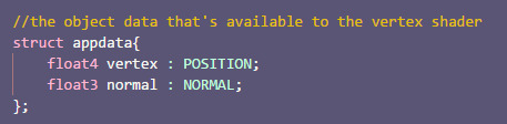
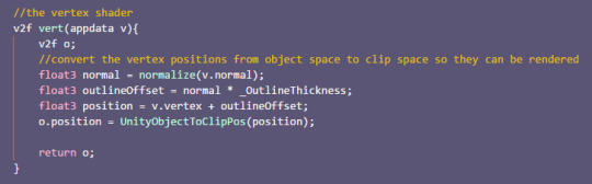
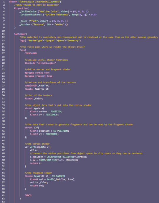
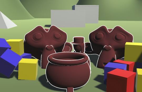
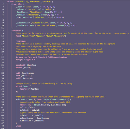
Multipass Shaders (& inverted Hull outlines)
So far we only ever wrote a color to the screen once per shader (or let unity generate multiple passes for us via surface shaders). But we have the possibility to draw our mesh multiple times in a single shader. A great way to use this is to draw outlines. First we draw our object as usual and then we draw it again, but we change the vertices a bit so it’s only visible around the original object, drawing a outline.
To understand this Tutorial it’s best if you understood surface shaders: https://ronja-tutorials.tumblr.com/post/172421924392/surface-shader-basics
The first version of this shader will be based on the simple unlit shader: https://ronja-tutorials.tumblr.com/post/172173911737/textures
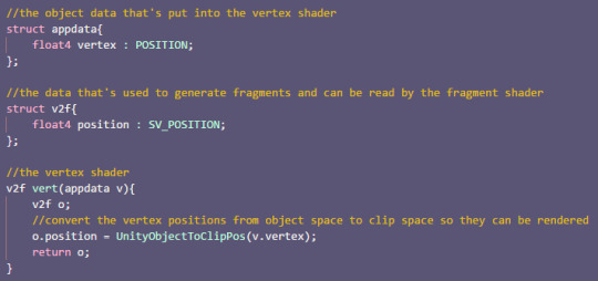
We already have a shader pass in this shader, so we just duplicate that for now. Because we’re writing the same information twice, this doesn’t change how the shader looks though.
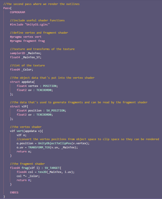
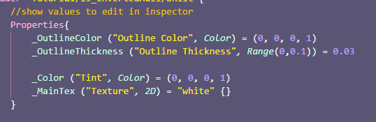
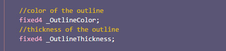
The next change is to set up our properties and variables. This second pass will only write a simple color to the screen so we don’t need the texture. we just need the outline color and the outline thickness. We put the properties in the properties area at the top like usual. It’s important that we put the new variables in the second pass though.
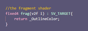
The next step is to rewrite our fragment shader to use the new variable instead of a texture. We can simply return the color without any additional calculations in there.
Because we don’t read from a texture in this pass, we can also ignore the uv coordinates, so we remove them from our input struct, our vertex to fragment struct and we stop passing them between the structs in the vertex shader.
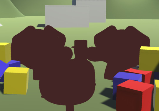
With those changes, we can see in the editor that the objects now simply have the color the outlines should have. That’s because our second pass simply draws over everything the first pass has drawn. That’s a thing we’re going to fix later though.
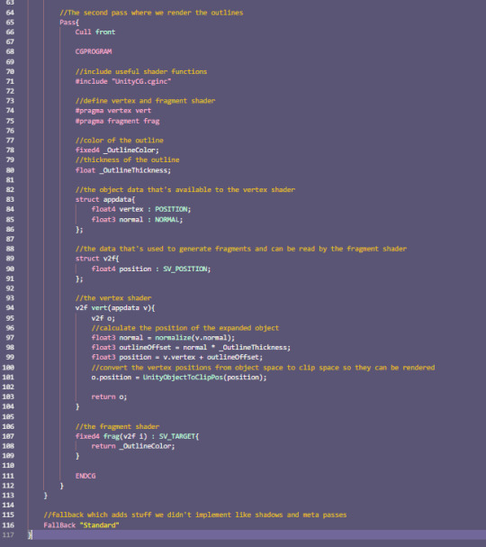
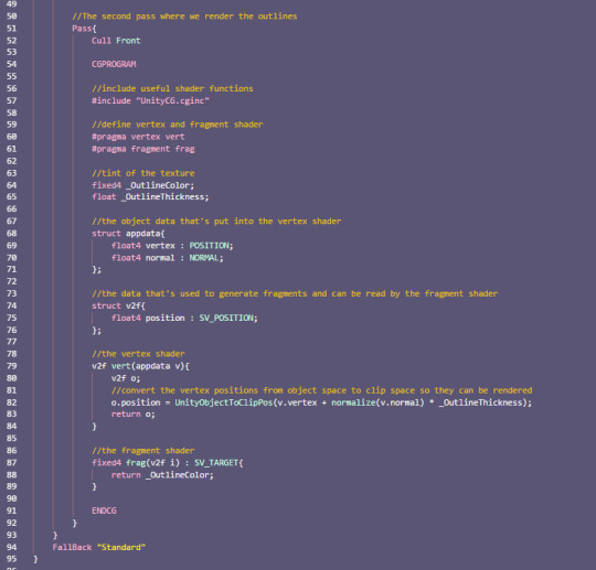
Before that we ensure that the outlines are actually outside of the base object. For that we simply expand them along the their normals. That means we need the normals in our input struct, then we simply add them to the position of the vertices. We also normalize the normals and multiply them with the outline thickness to make the outlines as thick as we want them to be.
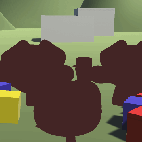
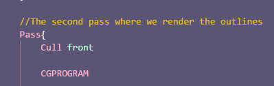
With this we can now adjust the thickness of our hull, but it’s still hiding the base objects. The fix for that is that we don’t draw the front of the hull. Usually when we render objects we only draw the front because of performance reasons (you might have looked inside a object before and were able to look outside, that’s why). For this we can now invert that and only draw the backside. That means we can still see the object because we can look into the hull and we can see the hull behinde the object because it’s bigger than the object itself.
To tell unity to not render the frontsides of objects we add the Cull Front attribute to the hull pass outside of the hlsl area.
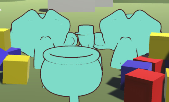
And with this we have the outlines how we want them.
It is pretty straightforward to also apply the outlines to a surface shader. Unity does generate the passes of the surface shader for us, but we can still use our own passes too which unity won’t touch so they operate as usual.
This means we can simply copy the outline pass from our unlit shader into a surface shader and have it work just as we expect it to.
The differences of outlines via a inverted hull shader to a postprocessing effect is that you can make the outlines on a material by material basis, you don’t have to apply it to all objects. Also it’s a different look than choosing outlines based on depth and normals. It’s best to inform yourself about both techniques and then choose which is better for your game.
I hope it’s now clear how shaders with multiple passes can work and how to use them to make outlines.
You can also find the source code for the shaders here:
https://github.com/axoila/ShaderTutorials/blob/master/Assets/19_Inverted_Hull/UnlitOutlines.shader
https://github.com/axoila/ShaderTutorials/blob/master/Assets/19_Inverted_Hull/SurfaceOutlines.shader
If you have any questions feel free to contact me here on tumblr or on twitter @axoila.
17 notes
·
View notes
Text
Outlines via Postprocessing
One of my favourite postprocessing effects are outlines. Doing outlines via postprocessing has many advantages. It’s better at detecting edges than the alternative (inverted hull outlines) and you don’t have to change all of your materials to give them the outline effect.
To understand how to create outlines via postprocessing it’s best to have understood how to get access to the depth and normals of the scene first: https://ronja-tutorials.tumblr.com/post/175679764562/postprocessing-with-the-normal-texture

We start with the shader and C# script from the postprocessing with normals tutorial.
The first changes we make is to remove properties and variables which were specific to the “color on top” shader. So the cutoff value and the color. We also remove the view to world matrix, because we our outlines don‘t have a specific rotation in the world so we can ignore it. Then we remove all of the code after the part where we calculate the depth and normals.

Then we remove the part where we write the camera matrix to the shader from our C# script.
The way we’re going to calculate the outlines is that we’re going to read from several pixels around the pixel we’re rendering and calculate the difference in depth and normals to the center pixel. The more different they are, the stronger the outline is.
To calculate the position of the neighboring pixels we need to know how big one pixel is. Luckily we can simply add a variable with a specific name and unity tells us the size. Because technically we’re working with texture pixels, it’s called the texelsize.
We can simply create a variable called texturename_TexelSize for any texture and get the size.

Then we copy the code for accessing the depth and normals, but change the names and we access the texture slightly to the right.

Now that we have two samples we can calculate the difference and draw it to the screen.

With this we can already see the outlines on the left side of the objects. Before we proceed with the next sample, I’d like to put the code for reading the sample and comparing it to the center values into a separate function so we don’t have to write it 4 times. This function needs the depth of the center pixel, the uv coordinates of the center pixel and the offset as arguments. We will define the offset in pixels because that’s the easiest for us to read.
So we simply copy the code from our fragment function to the new method and replace the depth and uv names with the names of the fitting arguments. To use the offset, we multiply it with the x and y coordinates of the texel size and then add the result to the uv coordinates just like previously.
After we set up the new method we call it in the fragment method and draw the result to the screen.

The result should look exactly like previously, but now it’s way easier to expand the shader to read samples in multiple directions. So we sample the pixels up, right and down too and add the results of all samples together.

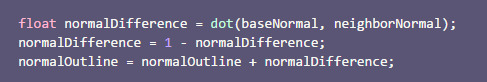
Using the depth already gives us pretty good outlines, but we can go further by also using the normals provided to us. We will also sample the normals in our compare function, but function can only return one value in hlsl so we can’t use the return value here. Instead of using the return value, we can add two new arguments with the inout keyword. With this keyword the value we pass into the function can be written to and the changes apply to the version of the variable pass in, not only the version in the function. Another thing we need to generate outlines from the normal is the outline of the center pixel, so we add that too to the list of our arguments.

Because we now have complete control over the outline variable we can now also do the adding to the existing outline in the method. After we changed that we go back to the fragment method, create a new variable for the difference of the normals and change the way we call the compare method to fit our new arguments.

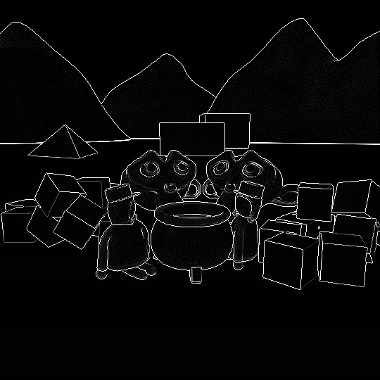
This again shouldn’t change the output of the method, but the new architecture allows us to also change the difference of the normal too. A easy and fast way to compare two normalised vectors is to take the dot product. The problem about the dot product is that when the vectors point in the same direction, the dot product is 1 and when the vectors move away from each other the dot product becomes lower, the opposite of what we want. The way to fixing that is to subtract the dot product from 1. Then, when the result of the dot product is 1 the overall result is 0 and when the result of the dot product becomes lower, the overall result increases. After we calculate the normal difference, we add it to the overall difference and we change the output to show the normal difference for now.

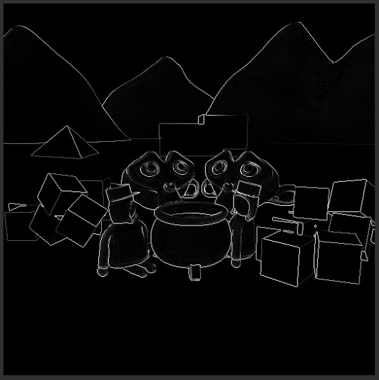
With those changes we can see outlines, but they’re different outlines than before because they’re generated from the normals instead of the depth. We can then combine the two outlines to generatecombined outline.

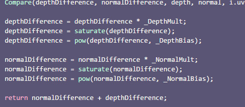
The next step is to make the outlines more customisable. To archieve that we add two variables for each depth and normal outlines. A multiplier to make the outlines appear stronger or weaker and a bias that can make the greyish parts of the outlines we might not want vanish.


To use the variables, after adding all of the sample differences, we simply multiply the difference variables with the multipliers, then we clamp them between 0 and 1 and get the difference to the power of the bias. The clamping between 0 and 1 is important because otherwise getting the exponent of a negative number can lead to invalid results. HLSL has it’s own function for clamping a variable between 0 and 1 called “saturate”.
With this you can now adjust your outlines a bit in the inspector - I boosted both normal and depth outlines a bit and reduced the noise by also increasing the bias, but it’s best to play around with the settings and see what fits your scene best.

Lastly we want to add our outlines to the scene, not just have them as a separate thing. For that we first declare a outline color as a property and shader variable.


To apply the outlines, at the end of the fragment function, we read from the source texture and do a linear interpolation from the source color to our outline color via the combined outline, that way the pixels that were previously black are now the source color and the white ones have the outline color.

The main disadvantages of postprocessed outlines are that you have to apply them to all object in the scene, The way the system decides what’s a outline and what isn’t might not fit the style your have in mind and you get aliasing (visible stairsteps) artefacts pretty quickly.
While there aren’t any easy fixes for the first two problems, you can mitigate the last one by using antialiasing in your postprocessing like FXAA or TXAA (the unity postprocessing stack provides those to you, but if you use v2 you have to redo the effect as a effect in the stack).
Another important point to keep in mind is that you have to use models that fit this way of doing outlines - if you put too much detail in your geometry the effect will paint most of your objects black, which is probably not the intended behaviour.

You can also find the source here:
https://github.com/axoila/ShaderTutorials/blob/master/Assets/18_OutlinesPostprocessed/OutlinesPostprocessed.shader
https://github.com/axoila/ShaderTutorials/blob/master/Assets/18_OutlinesPostprocessed/OutlinesPostprocessed.cs
I hope I was able to show you how to add nice outlines to your game and how it works.
If you have any questions feel free to contact me here on tumblr or on twitter @axoila.
9 notes
·
View notes
Text
Postprocessing with the Normal Texture
Another piece of information we can easily get our hands on thats very useful for postprocessing is the normals of the scene. They show in which direction the surface at any given pixel is pointing.
To understand how to get and use the normals of the scene it’s best to know how to access the scene depth first, I made a tutorial on how to do that here: https://ronja-tutorials.tumblr.com/post/175440605672/postprocessing-with-the-depth-buffer

We start this tutorials with the files from the depth postprocessing tutorial and expand them as we need.
The first change is to remove all of the code from the c# script which we used to drive the wave in the previous tutorial.

Then, we don‘t tell the camera to render the depth of objects anymore - instead we tell it to render a texture which includes the depth as well as the normals.

And that’s already all of the setup we need to access the normals. Next we edit our shader.
We also remove the all of the code used for the wave function here. Then we rename the _CameraDepthTexture to _CameraDepthNormalsTexture, so it’s written in by unity.


With this setup we can now read from the depthnormals texture in our fragment shader. If we just do that and just draw the texture to the screen, we can already see something interresting.


But what we can see isn’t what we really want, we only see red and green values and some blue in the distance. That’s because as it’s name suggests, this texture holds the normals as well as the depth texture, so we have to decode it first. Luckily unity provides us a method that does exactly that. We have to give it the depthnormal value as well as two other values the function will write the depth and the normals in.
Unlike the depth texture, the depth value we have now is already linear between the camera and the far plane, so we can easily adapt the code from the previous tutorial to get the distance from the camera again.


But let’s go back to using the normals. When we just print the normals as colors to the screen we already get a pretty good result.


But if we rotate the camera, we can can see that one point on a surface doesn’t always have the same normal, that’s because the normals are stored relative to the camera. So if we want the normal in the world we have to go additional steps.
We can easily convert our viewspace normals to world space, but sadly unity doesn’t provide us a function for that so we have to pass it to our shader ourselves. So we go back to our C# script and implement that.
First we get a reference to our camera, we already get the camera in our start method, so we can directly save it to a class variable right there. Then in the OnRenderImage method we get the viewspace to worldspace matrix from the camera and then pass it to our shader. The reason we can’t pass the matrix to our shader once in the start method is that we want to move and rotate our camera after starting the effect and the matrix changes when we do that.


Next we can use that matrix in our shader. we add a new variable for it and then multiply it with the normal before using it. We cast it to a 3x3 matrix before the multiplication so the position change doesn’t get applied only the rotation, that’s all we need for normals.


Now that we have the worldspace normals, we can do a simple effect to get comfortable with them. We can color the top of all objects in the scene in a color.
To do this, we simply compare the normal to the up vector. We do this via a dot product which returns 1 when both normalized vectors point in the same direction(when the surface is flat), 0 when they’re orthogonal (in our case on walls) and -1 when they’re opposite to each other(in our case that would mean a roof over the camera).

To make it more obvious what’s on top and what doesn’t count as on top, we can now take this smooth value and do a step to differentiate between top and not on top. If the second value is smaller, it will return 0 and we will see black, if it’s bigger, we will see white.


The next step is to bring back the original colors where we don’t define the surface to be on top. For that we just read from the main texture and then do a linear interpolation between that color and the color we define to be on top (white at the moment).


And as a last step we’re going to add some customizability. So we add a property and a global variable for the up cutoff value and the top color.


Then we replace the fixed 0.5 we used previously for our cutoff value with the new cutoff variable and linearly interpolate to the top color instead of the fix white color. We can then also multiply the up color with the alpha value of the top color, that way when we lower the alpha value the top will let some of the original color through.


This effect was mainly made to show how the depthnormals texture works. If you want a snow effect it’s probably better to just do it in the shader for the object the snow is on instead of a postprocessing effect. I’m sorry I didn’t come up with a better example.

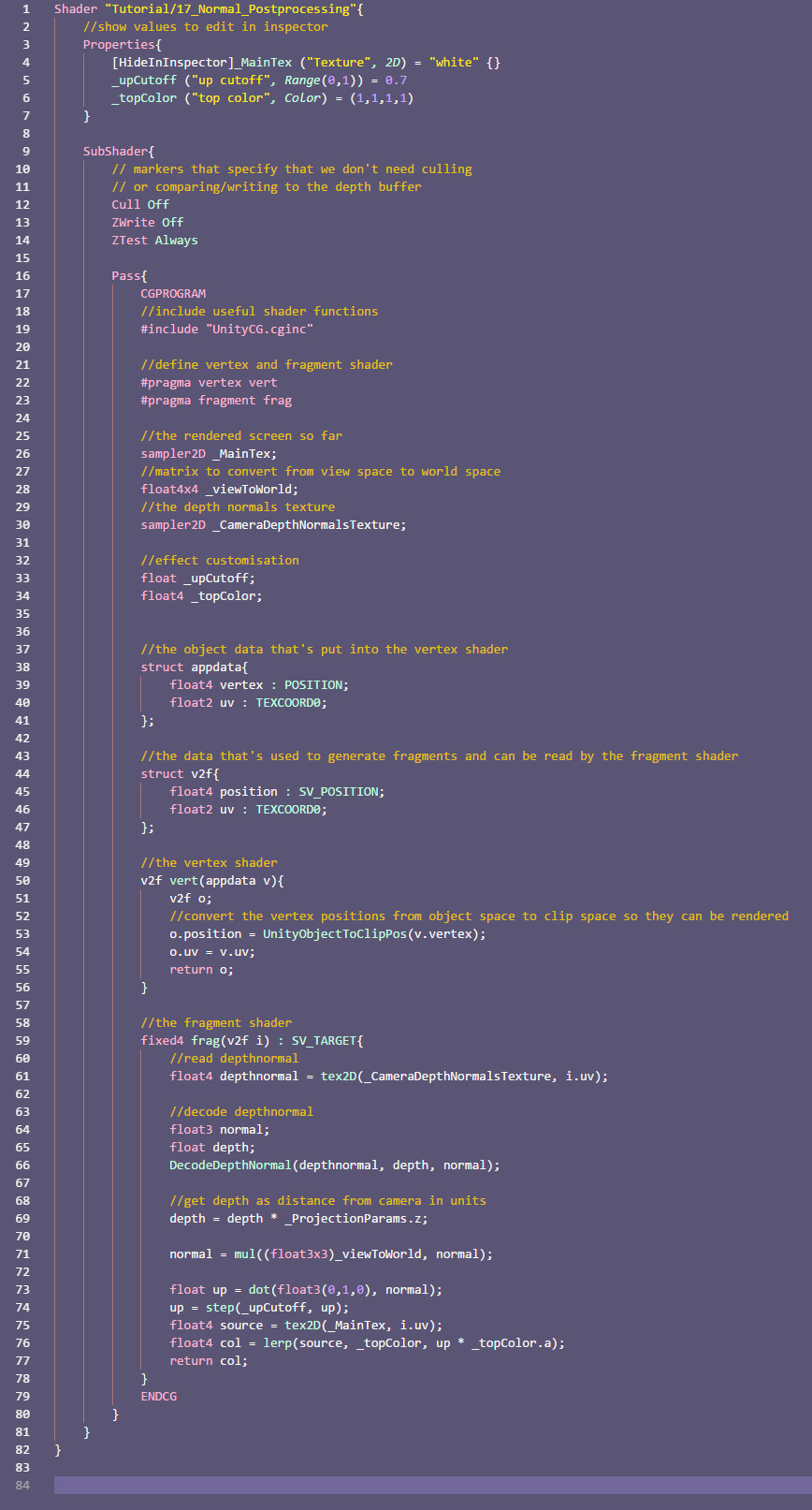
You can also find the source here:
https://github.com/axoila/ShaderTutorials/blob/master/Assets/17_NormalPostprocessing/NormalPostprocessing.cs
https://github.com/axoila/ShaderTutorials/blob/master/Assets/17_NormalPostprocessing/17_NormalPostprocessing.shader
I hope that I was able to convey how to access normal textures and that this will be a solid foundation for future effects.
If you have any questions feel free to contact me here on tumblr or on twitter @axoila.
9 notes
·
View notes
Text
Postprocessing with the Depth Buffer
In the last tutorial I explained how to do very simple postprocessing effects. One important tool to do more advanced effects is access to the depth buffer. It’s a texture in which the distance of pixels from the camera is saved in.
To understand how postprocessing effects with access to the depth buffer work it’s best to understand how postprocessing works in general in unity. I have a tutorial on that here: https://ronja-tutorials.tumblr.com/post/175172770247/postprocessing

We will start this with the files we made in the simple postprocessing tutorial and go from there.
The first thing we expand is the C# script which inserts our material into the rendering pipeline. We will expand it so when it starts up it will look for the camera on the same gameobject as itself and tell it to generate a depth buffer for us to use. This is done via the depthtexture mode flags. We could just set it to render the depth buffer, but what we’re going to do is take the existing value and take a bit-or with the flag we want to set, this way we don’t overwrite the flags other scripts might set to render their own effects. (you can read up on bitmasks if you’re curious how that works)

That’s already everything we have to change on the C# side to get access to the depth texture, so we can now start writing our shader.
We get access to the depth texture by creating a new texture sampler which we call _CameraDepthTexture. We can read from the sampler like any other texture, so we can just do that and look at how the depth texture looks like. Because the depth is just a single value, it’s only saved in the red value of the texture and the other color channels are empty so we just take the red value.


After doing this and starting the game, chances are high that the game looks mostly black. That’s because the depth isn’t encoded linearly, the distances closer to the camera are more precise than the ones further away because that’s where more precision is needed. If we put the camera very close to objects we should still be able to see some brighter color, indicating that the object is close to the camera. (if you still see black/mostly black when putting the camera close to objects and would like to, try increasing your near clipping distance)

To make this more usable for ourselves we have to decode the depth. Luckily unity provides a method for us that takes the depth as we have it now and returns the linear depth between 0 and 1, 0 being in the camera and 1 being at the far clipping plane. (if your image is mostly black with a white skybox here, you can try to lower the far clipping plane of your camera to see more shades)


The next step is to completely decouple the depth we have from the camera settings so we can change them again without changing the results of our effects. We archieve that by simply multiplying the linear depth we have now with the distance of the far clipping plane. The near and far clipping planes are provided to us by unity via the projectionparams variable, the far clipping plane is in the z component.


Because most objects are further away than 1 unit from the camera, the image will be primarily white again, but we now have a value we can use that’s independent of the clipping planes of the camera and in a unit of measurement we can understand (unity units).
Next I’m going to show you how to use this information to make a wave effect that seemingly wanders through the world, away from the player. We will be able to customize the distance from the player the wave has at the moment, the length of the trail of the wave, and the color of the wave. So the first step we take is to add those variables to the properties and as variables to our shader. We use the header attribute here to write wave in bold letters over the part with variables for the wave in the inspector, it doesn’t change the functionality of the shader at all.
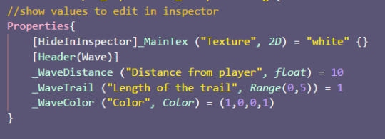


The wave example will have a hard cut at it’s front end and a smooth tail behind that. We start by making a hard cut based on the distance. For this we use the step function which returns 0 if the second value is greater or 1 otherwise.


Then to define the trail we use a smoothstep function which is similar to the step function, except we can define two values to compare the third value to, if the third value is less than the first, the function returns 0, if it’s bigger than the second it returns 1, other values return values between 0 and 1. I like to imagine it like a inverse linear interpolation because you can take the result of the smoothstep and put it into a lerp with the same minimum and maximum values as the smoothstep to get the value of teh third argument.
In this case the value we want to compare to is the depth, our maximum is the wave distance and the minimum is the wave distance minus the trail length.


You might notive that the front and the trail of the wave are opposite, it would be easy to fix that (flip the two arguments of the clip or flip the min orthe max of the smoothstep), but in this case it’s on purpose. Because if we multiply any number by zero it becomes zero, we can now multiply the front and the trail of the wave and it will become zero in front and behind the wave with only a small white wave in the middle at our defined distance.

Now that we have defined our wave, we can bring back color to the image. For that we first have to sample our source image again and then we do a linear interpolation from the source image to our wave color based on the wave parameter we just calculated.


As you can see we have a artefact with this approach when the distance reaches the far clipping plane. Even though the skybox is technically at the distance of the far clipping plane, we don’t want to show the wave when it reaches it.
To fix this we read the source color just after we calculate the depth and return it instantly if the depth is at the far clipping plane.

One last thing I’d like to do is expand the C# script to automatically set the distance for us and make it slowly go away from the player. I’d like to control the speed the wave travels and if the wave is active. Also we have to remember the current distance of the wave. For all of that we add a few new class variables to our script.

Then we add the update method which is called by unity automatically every frame. In it we increase the distance of the wave if it’S active and set it to zero when it isn’t, this way the wave is reset and comes from the player every time we enable it again.

And then to use the wavedistance variable in our shader we set it. We do the setting in the OnRenderImage just before the method is used, that way we can make sure that when it’s used it’s set to the correct value.


You can also find the source code for this tutorial here:
https://github.com/axoila/ShaderTutorials/blob/master/Assets/16_DepthPostprocessing/DepthPostprocessing.cs
https://github.com/axoila/ShaderTutorials/blob/master/Assets/16_DepthPostprocessing/16_DepthPostprocessing.shader
I hope I was able to explain how to use the depth buffer for postprocessing effects and you’ll be able to make your own effects now.
If you have any questions feel free to contact me here on tumblr or on twitter @axoila.
7 notes
·
View notes
Text
Postprocessing
We used all shaders we wrote in this tutorial until now to render models to the screen. Another way shaders are commonly used is to manipulate images with them. That includes the image we’re drawing to the screen as we render our game. When manipulating the render output after we rendered our objects to the screen it’s called postprocessing.
Postprocessing still uses the same shader language and structure as shaders that render surfaces, so I’d recommend you to know how to render surfaces first. If you have read/understand my tutorial about rendering textures you should be fine. https://ronja-tutorials.tumblr.com/post/172173911737/textures

As a simple introduction into postprocessing, I’m going to show you how to make a shader which inverts the colors of an image.
Because most of the structure is the same as other shaders, we’re going to use the textured shader as a base for this one, you can find it here: https://github.com/axoila/ShaderTutorials/blob/master/Assets/03_Textures/textures.shader

This simple shader already has some things we don’t need if we don’t render surfaces with it which we’re going to remove. I’m removing the tint color(we can keep it if we wanted to tint the image), the tags (unity can read when and how to render objects, but like I mentioned, we’re not rendering objects with the shader), the texture transforms (maintex will be the image before we apply the shader to it and we always want the whole scene), the transform tex macro (because it uses the texture transform and we don’t use that anymore, but we still want to write the uv coordinates into the v2f struct) and the part where the tint color is used.
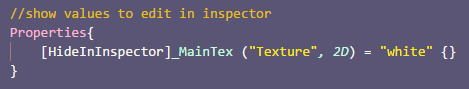
Then we will add a few details which to make the shader work better as a postprocessing shader. Those are the hide in inspector tag for the main texture property because it will be set from code and markers that tell unity to not perform any culling or writing/reading to the depth buffer.
After those changes, the shader should look roughly like this.

Now that we have the base of our postprocessing shader, we can write the C# script that will make the camera use the script.
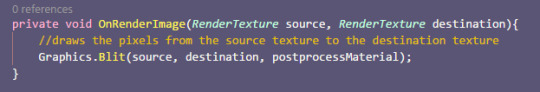
We will need a normal monobehaviour, with only one method called OnRenderImage. The method will automatically be called by unity. It’s passed two arguments, one rendertexture with the rendered image and one rendertexture we can write into that’s used as the rendered image afterwards. To move image data from one rendertexture to the other, we use the blit method.
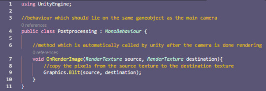
So far this script wouldn’t do anything because it doesn’t change the image at all. For it to do that we can pass the blit function a material to use to draw the texture as a third parameter. We’ll add a material as a serialized class variable and then pass it to the blit function to do that.
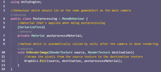
With this set up, we can then set up our scene. First we add a new Material to our project and apply our postprocessing shader to it.

Then we take the gameobject with our camera on it and the C# script we wrote. Then we add our new material to the component.

With this our setup is complete, we should see the image like normal. To use this to invert the colors of our image, we go back into our shader and edit the fragment function. Instead of just returning the color of the input texture, we first invert the color by calculating 1 minus the color and then return it.


Inverting the color is obviously not a thing you often want to do, but this opens up many possibilities for future effects, some of which I will show in the next weeks.


You can also find the source code for this tutorial here:
https://github.com/axoila/ShaderTutorials/blob/master/Assets/15_Postprocessing/15_Postprocessing.shader
https://github.com/axoila/ShaderTutorials/blob/master/Assets/15_Postprocessing/Postprocessing.cs
I hope you learned how to do simple postprocessing in unity and are ready to make simple postprocessing shaders yourself.
If you have any questions feel free to contact me here on tumblr or on twitter @axoila.
0 notes
Text
Vertex Manipulation
So far we only used the vertex shader to move vertices from their object coordinates to their clip space coordinates (or to the world space coordinates which we then used for other things). But there are more things we can do with vertex shaders. As a introduction I’m going to show you how to apply a simple sine wave to a model, making it wobble.
I will make the shader with a surface shader so you should know the basics of surface shaders(https://ronja-tutorials.tumblr.com/post/172421924392/surface-shader-basics), but it works the same with any other type of shader.

When manipulating the positions of our surface, we use the vertex shader. So far we didn’t write a vertex shader in our surface shader, it was instead generated by unity in the background. To change that we add the declaration for it in our surface shader definition by adding the vertex:vertexShaderName part.

Then we have to write the actual vertex function. Previously, in unlit shaders, we calculated the clip space position in there, but even when using vertex shaders, that part is generated for us in surface shaders. We manipulate the object space vertex positions and then let them be processed by unity.
Because the input struct has to have variables with specific names, it’s easiest to use a input struct unity provides for us here, it’s called appadata_full, but we could also use our own struct here if it uses the same terminology.
Just like the surface shader, the vertex shader in surface shaders (there should be better terminology for this) doesn’t return anything, instead it takes a parameter with the inout keyword we can manipulate.
Because surface shaders generate the conversion to clip space for us, a empty vertex function is all we need to make our shader work just like before.

A simple thing we can do to our mesh is multiply all of our vertices by a value to make the model bigger. (a *= b is the same as a = a * b but a bit shorter)


While the model is bigger we also see a weird artefact here. The shadow is still calculated based on the original, unmodified vertex positions. That’s because the surface shader doesn’t automatically generate a shadow pass (used for casting shadows) for our new vertex positions. To fix that we expand our surface definition with the hint addshadows and the artefects should be gone.


To make the shader more interresting we’ll change the vertex shader. Instead of making the model just bigger, we’ll offset the y position based on the sine of the x position, making it wavy.


This results in big waves with a low frequency, so we’ll add two variables to change those properties.


With this we have nice customizable waves on our model, but sadly the normals of our deformed models are wrong. We only moved the positions, not the normals.

The easiest and most flexible way to generate correct normals for custom geometry is to calculate the custom geometry for neighboring surface points and recalculate the normal from that.
To get neighboring surface points we can follow the tangent and bitangent of the surface. The normal, the tangent and the bitangent are all orthogonal to each other. The tangent and the bitangent both lie on the surface of the object.

Normal in blue, tangent in red and bitangent in yellow.
Luckily the tangent are already saved in the model data, so we can just use them. The bitangent isn’t, but we can calculate it easily by taking the cross product of the normal and the tangent (taking the cross product of two vectors returns a vector that’s orthogonal to both).
After we obtain the bitangent we create two new points that are almost at the vertex position, but slightly changed, and give them the same treatment we gave the original position.

With those positions we can now calculate the new normal of the surface. For that we calculate a new tangent and bitangent from the positions by subtracting the modified base surface position from the modified surface positions where we added the tangent/bitangent previously. And after obtaining the new tangent and bitangent, we can take their cross product to get the new normal which we then use.


The last thing I’d like to add to this shader is movement over time. So far we only use the x position of the vertex as a changing parameter in our function which generates the new vertex positions, but adding the time to that is pretty easy.
Unity passes the time to all shaders automatically as a 4-dimentional vector, the first component of the vector is the time divided by 20, the second just the time in seconds, the third the time multiplied by 2 and the fourth contains the time multiplied by 3. Because we want to adjust the time via a external property we use the second component, with the time in seconds. We then add the time multiplied by the animation speed to the x position.


I increased the offset of the sampled surface positions a bit (up to 0.01 units) to smooth over the artefacts better. A small distance can represent a more complex distortion better while bigger distances smoothes over some things.

You can also find the source code for this tutorial here:
https://github.com/axoila/ShaderTutorials/blob/master/Assets/14_VertexManipulation/14_vertexmanipulation.shader
I hope I was able to explain how to start manipulating vertices and you find your own ways of making nice looking shaders with this technique.
If you have any questions feel free to contact me here on tumblr or on twitter @axoila.
0 notes
Text
Polygons
Of course everything we render so far is made of polygons, but someone asked me how to clip a polygon shape based on a list of points in a shader so I’ll explain how to do that now. I will explain how to do that with a single shader pass in a fragment shader, a different way would be to actually generate triangles based on your polygon and use stencil buffers to clip, but I won’t explain that in this tutorial.
Because this tutorial explains a simple technique that doesn’t do that much with fancy graphics I will explain it in a unlit shader, but it will work the same way in surface shaders. The base for this tutorial will be my simple shader with properties, so you should know how to do that before starting this tutorial: https://ronja-tutorials.tumblr.com/post/172170158512/properties

The first thing we have to add to our shader is the world position. Like in the other shaders (planar, triplanar and chessboard) we do that by multiplying the object position with the object to world matrix and pass that value to the fragment shader.


Then we can progress to the fragment shader. here we start by calculating which side of a line a point is of. Since we will later generate our lines based on points, it’s easiest to define them as two points the line goes through.
To calculate which side of the line a point is on, we generate two vectors, first, a vector which goes from a arbitrary point of the line to our point and second the “line normal”. Usually the concept of a line normal doesn’t make much sense, but here we need a left and a right side of the line so we can define the line normal as a vector that points orthogonally to the left of the line direction.
When we have those vectors we can calculate their dot product and get the side the point is on. If the dot product is positive, the vector to the point points somewhat in the same direction as the line normal and it’s on the side the line normal points towards. If the dot product is negative the vector to the point points somewhat in the opposite direction as the line normal and the point is on th other side. If the dot product is exactly zero, the vector to the point is orthogonal to the line normal and the point is on the line.

To do this in shader code, we start by defining two points that define a line and then calculating those three vectors we need. We start by calculating the line direction. We get it by subtracting the first from the second line point (when calculating the difference between two points we always have to subtract the start from the goal if we care about the direction). Then we rotate the line point by 90 degree by switching it’s x and y components and inverting the new x part(if we inverted the y part we’d have a vector that points to the right of the line). And lastly we subtract one of the points defining the line from the point we’re checking to get the vector to the point.
After that we take the dot product of the line normal and the vector to the point and draw it to the screen.


As you can see, we actually see a small gradient at the line we defined. But we don’t really want a gradient, we want a clear differentiation. The gradient is here, because all colors below 0 (to the right of the line) are counted as black, all colors between 0 and 1 (just to the left of the line) are greyscale values and all colors of 1 and higher(way to the left of teh line) are displayed as white. A easy fix for that is the step function which takes two values and returns 0 if the value to the left is bigger and 1 otherwise. So if we give the step function a 0 and the result of our dor product it will give us a clear distinction between the two sides.


We continue by adding a new point and two new lines which should allow us to make a triangle. For that it’s best to put the calculations we made so far in a method to reuse them more easily. For that we move all of our calculations to a new method and take the information we use as arguments, so in this case we want to take the point we want to check, the first point of the line and the second point of the line as arguments.

When we want to combine the multiple results of the lines we can do that in different ways, we can either define the result to be true if it’s to the left of all lines and false otherwise or we can say the result is true if it’s left of one or more lines and only false if it’s to the right of all lines. The triangle I defined goes clockwise, that means the left of the lines is outside, that means to differentiate between inside and outside of the polygon we have to find the union of all “left side” fragments. We do that by adding the results of the lines, the outsides will add up and have values of 1 or higher, the inside of the polygon will have a value of 0 everywhere.


Now that we can display a polygon sucessfully, I’d like to expand it so we can edit it more easily without editing the shader code. For that we add two new variables, a array of positions and how much that array is filled. The first one will hold all of the points of our polygon, the second one is there because shaders don’t support dynamic arrays, so we have to choose a length for the array and then we fill it more or less.

There are no properties for arrays, so we have to fill them via C# code. I added two attributes to the new class, execute in edit mode to make the script update our polygon without us starting the game and require component, to make sure the script is on the same gameobject as the renderer which has the material with the shader we’re writing.

We then add two variables to the class, the material with the shader and a array of points which we will then pass to the shader. The material is private, because we’ll get it via code and it’s only used in this class. The position array is also private because we don’t need access from outside, but we give it the serialize field attribute to make unity remember the value and show it in the inspector.

Then we write the method which will pass the information to the shader. In it we first check if we already fetched the material and get the renderer on the gameobject and get it’s material if we didn’t. We use the sharedmaterial field of the renderer for this because if we used the material field we’d create a copy of the material which we don’t want hight here.
Then we allocate a new array of 4d vectors which can hold 1000 variables. The reason we use 4d vectors instead of the 2d vectors we need is that the unity API only allows us to pass 4d vectors and the reason for the 1000 variable length is that as I mentioned previously shaders don’t support dynamic array lengths so we have to choose a maximum of points and always choose that length, I chose 1000 pretty much randomly.
We then fill this array with the positions of our points, the 2d vectors will automatically be converted to 4d vectors with 0 at the 3rd and 4th position.
After we prepared our vector array we pass it to our material and then also pass it the amount of positions we actually use.

The next step is to actually call this function, we do this in two methods, one which we call Start and one which we call OnValidate. The first one will automatically called by unity when the game starts and the second one will automatically be called by unity when a variable of the script changes in the inspector.

After writing the script we can add it to our project to do it’s job. We just add it as a component to the same gameobject the renderer with our material is on. And when we set up our script, we can set our corners easily by adding to the array in the inspector.

Next we go back to our shader to actually use the array. To do that we instantiate our outside triangle variable as zero.
Then we iterate over the array with a typical for loop. We start the loop at 0 because the first index of arrays in hlsl is adressed 0, the second with 1 etc... we stop when the iterator value goes over the amount of corners we specified via C# and we increase the iterator by 1 every loop. We explicitely tell hlsl to loop the for loop, the alternative would be to unroll it which means it would just copypaste the stuff happening in the for loop under each other. Unrolling is usually faster in shaders, but we don’t have a fixed length in our case so we have to use loop.
In the loop, we just add the return value of the side function of one line. As the points of the line we use the corner at the position of the iterator and the corner at the position of the iterator plus one. The problem that emerges when we use that plus one is that at the last point we acess the array at a point we didn’t set, but we want to go back to the first point instead. In this position modulo helps us, we add one to the iterator and then take the modulo with the length of the valid array, that way it jumps back to 0 if it would acess a invalid value otherwise.


And with that we have a polygon just based on a few points (if it doesn’t show for you, just nudge the values in the inspector a bit to call OnValidate).
The person who requested this tutorial asked how to clip a polygon, so that’s the last thing we’re going to add here. In hlsl there is a function to discard polygons called clip. We pass it a value and if that value is lower than 0 the fragment won’t be rendered, otherwise the function does nothing.
We can pass the outsideTriangle variable into the clip function, but nothing will happen because all values of the value are 0 or higher. To actually clip everything outside of the polygon we can simply invert the value and the values inside of the polygon will stay 0 and all of the values outside will be negative and will be clipped.
Because we now use the outsideTriangle variable for it’s intended use, we can now stop drawing it to the screen and just print the color again.


The biggest disadvantage with this technique is that we can only render convex polygons, it breaks when we try to use concave ones.


You can also find the source code for this tutorial here:
https://github.com/axoila/ShaderTutorials/blob/master/Assets/13_Polygon/Polygon.shader
https://github.com/axoila/ShaderTutorials/blob/master/Assets/13_Polygon/PolygonController.cs
I hope you learned something about how to approach problems with multiple points and vectors. And I hope I talked about what you wanted to know, Alex.
If you have any questions feel free to contact me here on tumblr or on twitter @axoila.
3 notes
·
View notes
Text
Custom Surface Lighting Function
Surface shaders are wonderful and being able to use the Standard PBR model is very powerful. But we don’t always want the PBR light. Sometimes we want to change the way we treat lighting to get a different, often more cartoonish, look. Custom lighting functions allow us to do exactly that.
This tutorial is about a surface shader specific feature, while the basics of lighting are the same in all shaders, you need a lot more code to archieve the same result from a non-surface shader and I won’t explain it in this tutorial.
This tutorial will build on the result of the surface shader basics tutorial and I recommend you to have understood it: https://ronja-tutorials.tumblr.com/post/172421924392/surface-shader-basics

We start by changing the lighting function to a custom lighting function we’ll write ourselves.

Then we add a method to our shader which will be our lighting function. The name of this function has to be LightingX where X is the name of our lighting method we reference in the surface definition. In this definition of the method we’re using here, we get the surfaceoutput we return from the surface shader, as well as the direction the light is hitting the surface point from and the attenuation (I’ll explain later what that does).

You might notice that I use the SurfaceOutput struct here instead of SurfaceOutputStandart struct. That’s because our custom lighting model won’t use metalness and softness, so we can use the struct meant for non-PBR materials (you can use SurfaceOutputStandard for your custom lighting functions if you want to, but you’ll have to import UnityPBSLighting.cginc). To use the SurfaceOutput struct, we also have to return it in our surface shader function and remove the parts where we set the metal and smoothness values.
I also removed metalness and smoothness from the shader variables and properties because we don’t use them anymore, but it’s not critical that you do this.

After doing this, we should have a lighting function that unity uses, but it returns 0 (black), so we can’t see any lights.

The reason we can still make out shapes and it’s not solid black is that unity does global illumination and tries to approximate environment lighing by looking at the skybox, if we change environment lighting to black in the lighting tab, we will see our shape solid black, but our lighting will work anyways, so you can try out what you think makes your game look most like you want it to (I’ll keep it at the default settings).
Next we’ll implement a simple lighting model. The first step is to get the dot product between the vector from the surface to the light and the normal. Luckily unity provides both to us, and both are already in worldspace as well as normalized(they have the length of 1), so we don’t have to convert them.
The dot product then tells us how much the surface points towards the light. It has a value of 0 where the surface is paralell to the direction to the light, is has a value of 1 where the light points towards the light and a value of -1 where the surface points away.


The lighting method we’re going to implement is pretty simple, but also very versatile. We’re going to use the amount the surface points towards the light to look up a value of a texture and use that as our brightness.
For that we have to change the variable from values that go from -1 to 1 to values between 0 and 1 (because UV variables go from 0 to 1), we do that by multiplying it by 0.5 (then it has a range from -0.5 to 0.5) and then adding 0.5 (shifting the range to 0 to 1 where we want it).
Next we add a new texture to our shader as a shader variable as well as a property. I’ll name it ramp, because the lighting technique is usually called toon ramp. Then we read from that texture in the lighting function and return the value we read from that. I’ll use a function that’s half black and half white so we should see a clear cut on the model.


This is the texture I use in this example:


You can see that we can already see the albedo in the shadows here, that’s again because of the environment lighting calculations unity adds in the background, but it will look better soon.
Namely, to make it look better, we’re going to multiply the light intensity with the albedo of the material so we see our colors correctly as well as the attenuation, which includes casted shadows as well as the light falloff, so the light gets darker in the distance and the light color, so the object gets tinted in the color it gets illuminated in.


That’s the whole shader. The advantage of it is that we can now add all kinds of different toon ramps, including ramps with colors. For example this ramp which has a warm front side and a blueish cold backside with a exaggerated transition I got from the unity examples (https://docs.unity3d.com/Manual/SL-SurfaceShaderLightingExamples.html).


One thing we didn’t write for our shader, which still works though is emission. Because emission is the light the object itself emits it’s independent from other lights and not calculated in the lighting function.
This toon shader is wonderful and flexible and I’ve seen it used in many places.
Lighting functions in general are very useful and powerful. One thing to keep in mind though is that they only work in forward rendering. When you switch your render mode to deferred you can still see the objects like you’re used to, but they can’t take advantage of deferred rendering (don’t worry about it and stick to forward rendering if you don’t know the difference).

You can also find the source code for this shader here: https://github.com/axoila/ShaderTutorials/blob/master/Assets/12_CustomSurfaceLighting/CustomLighting.shader
I hope I could explain how to implement custom lighting functions into surface shaders.
If you have any questions feel free to contact me here on tumblr or on twitter @axoila.
3 notes
·
View notes
Text
Fresnel Effekt
One of the most common effects people use in shaders in a fresnel effect. With a fresnel you can darken, lighten or color the outline of your objects, increasing the sense of depth.
For this tutorial we will make a surface shader, so if you follow it directly you should know the basics of surface shaders. You can find a explanation of them here: https://ronja-tutorials.tumblr.com/post/172421924392/surface-shader-basics. But you can also use a fresnel effect for unlit shaders, giving your objects some smoothness and tangibility without having to implement expensive lighting.

We start with the surface shader modify it to show the fresnel. The fresnel uses the normals of the object to determine the intensity of the effect. To get the normals in worldspace in our shader, we add the worldNormal attribute to our input struct as well as the internal data macro. We won’t interact with the internal data at all, but unity needs it to generate the worldspace normal.
You can generate the worldspace normals in non-surface shaders with a simple matrix multiplication, it’s explained in my triplanar mapping tutorial: https://ronja-tutorials.tumblr.com/post/173806265932/triplanar-mapping

To get a gradient from that, we take the dot product with another normalized vector. When you take the dot product of two normalized vectors, you get a value that represents how much they align. If they point in the same direction, the dot product returns 1, if they are orthogonal it returns a 0 and if the vectors are opposing it returns a -1.


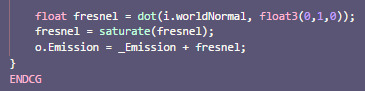
First we will just get the dot product of the normal and a static vector so see better how it works. We then write the result into the emission channel, so we can see it well.


We can now see that the surface gets brighter where it points up and darker where it points down. To prevent weird results with negative emission, we can clamp the fresnel value to the values between 0 to 1 before using it. For that we’ll use the saturate method. It does the same as a clamp from 0 to 1, but is faster on some GPUs. With that change we see how the fresnel only effects the top of our objects.

The next step is to make the effect relative to our view direction instead of a fixed direction. In surface shaders we get the view direction by just adding it to our input struct.
If you’re making a unlit fresnel shader, you can get the view direction by subtracting the camera position from the world position of your vertex (I explain how to get the worldspace position in my planar projection tutorial (https://ronja-tutorials.tumblr.com/post/173237524147/planar-mapping) and you can get the camera position from the builtin variable _WorldSpaceCameraPos (you can just use it in your code without adding anything else)).


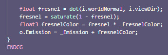
That’s already working pretty well, but instead of the outside of the material, it’s illuminating the center of it. To invert that, we simply subtract if from 1, so the bright areas in this version don’t affect the color any more and the unaffected parts get highlighted.

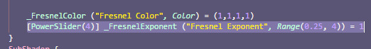
To finish this shader off I’d like to add some customisation options. First we add a fresnel color. For that we need a property and a value for that and then multiply our fresnel value with that color.


Next I’ll add a possibility to make the fresnel effect stronger or weaker by adding a exponent to it. I also add the powerslider attribute to the property of the exponent. That way values closer to 0 take up more space on the slider and can be adjusted more accurately (in this example the part of the slider from 0.25 to 1 is almost as big as the part from 1 to 4).
Exponents are pretty expensive so if you find a way to adjust your fresnel that fits you just as well it’s probably better to switch to that, but exponents are also easy and nice to use.


A fresnel effect can also be used to fade textures or other effects and a lot of other things, but that’s for another tutorial.

You can also find the source code for this shader here https://github.com/axoila/ShaderTutorials/blob/master/Assets/11_Fresnel/11_Fresnel.shader
I hope I could help you understand how fresnel effects work and you can use them for your own shaders if you want to.
If you have any questions feel free to contact me here on tumblr or on twitter @axoila.
8 notes
·
View notes
Text
Chessboard Pattern
For me, one of the most interresting things to do with shaders is procedural images. To get started with that, we’re going to create a simple Chessboard pattern.
This tutorial will build on the simple shader with only properties https://ronja-tutorials.tumblr.com/post/172170158512/properties, but as always, you can also use the technique to generate colors in more complex shaders.

I will take the world position of the surface to generate the chessboard texture, that way we can later move and rotate the model around and the generated patterns will fit together. If you want to pattern to move and rotate with the model, you can also use the object space coordinates (the ones from appdata, not multiplied with anything).
To use the worldposition in the fragment shader, we add the world position to the vertex to fragment struct and then generate the world position in the vertex shader and write it into the struct.

Then in the fragment shader, we can start by first doing a 1D chess field, so just alternating black and white lines. To do that, we take one of the axis of the position and modify the value. We start by flooring it. That means it’ll be the next smaller whole number. We do that to make sure we only have one color per unit.
Then we find out wether our field is a even or a odd one. To do that, we divide the value by two and take the fractional part (the part of the number after the dot). so now the even numbers are all 0(because after a division by 2 even numbers are still whole numbers, so their fractional part is 0) and all of the odd fields result in 0.5(because after a division by 2 odd numbers end up fractional, 1 becomes 0.5, 3 becomes 1.5...). To make the odd numbers white instead of grey, we can then multiply our value by 2.


Next, we make the pattern two dimensional. To do that we only have to add a additional axis to the value we’re evaluating. That’s because when we add one to our rows all of the even values become odd and the odd values become even. This is also the main reason why we floor our values. We easily could have made the pattern work in one dimension without flooring them, but this makes it easier to add more dimensions.


After that we can go even further and add the third dimension in the same way as we added the second.


Next I’d like to add the ability to make the pattern bigger or smaller. For that, we add a new property for the scale of the pattern. We divide the position by the scale before we do anything else with it, that way, if the scale is smaller than one, the pattern is generated as if the object is bigger than it is and as such it has more pattern density per surface area.
Another small change I made is that we now use floor on the whole vector instead of the components separately. That doesn’t change anything, I just think it’s nicer to read.


Finally I’d like to add the possibility to add Colors to the Pattern, One fo the even areas, one for the odd. We add two new Properties and the matching values for those colors to the shader.
Then at the end of our fragment shader, we do a linear interpolation between the two colors. Since we only have two different values (zero and one), we can expect the interpolation to return either the color it interpolates from(for a input of 0) or the color it interpolates towards(for a input of 1). (If you’re confused by the interpolation, I explain it more thouroghly in this tutorial: https://ronja-tutorials.tumblr.com/post/173543764442/interpolating-colors)


You can also find the source code for this shader here https://github.com/axoila/ShaderTutorials/blob/master/Assets/10_ChessBoard/Chessboard.shader
I hope you liked making this simple chess board shader and it helped you understand how to create patterns in shaders with simple math operations.
If you have any questions feel free to contact me here on tumblr or on twitter @axoila.
2 notes
·
View notes
Text
Triplanar Mapping
I made a tutorial about planar mapping previously. The biggest disadvantage of the technique is that it only works from one direction and breaks when the surface we’re drawing isn’t oriented towards the direction we’re mapping from (up in the previous example). A way to improve automatic uv generation is that we do the mapping three times from different directions and blend between those three colors.
This tutorial will build upon the planar mapping shader (https://ronja-tutorials.tumblr.com/post/173237524147/planar-mapping), but you can use the technique with many shaders, including surface shaders.

To generate three different sets of UV coordinates, we start by changing the way we get the UV coordinates. Instead of returning the transformed uv coordinates from the vertex shader we return the world position and then generate the UV coordinates in the fragment shader.

We use transform tex to apply the tiling and offset of the texture like we’re used to. In my shader I use xy and zy so the world up axis is mapped to the y axis of the texture for both textures, not rotating them in relation to each other, but you can play around with the way use use those values (the way the top UVs are mapped is arbitrary).

After obtaining the correct coordinates, we read the texture at those coordinates, add the three colors and divide the result by 3 (adding three colors without dividing by the number of colors would just be very bright).


Having done that our material looks really weird. That’s because we display the average of the three projections. To fix that we have to show different projections based on the direction the surface is facing. The facing direction of the surface is also called “normal” and it’s saved in the object files, just like the position of the vertices.
So what we do is get the normals in our input struct, convert them to worldspace normals in the vertex shader (because our projection is in worldspace, if we used object space projection we’d keep the normals in object space).
For the conversion of the normal from object space to world space, we have to multiply it with the inverse transposed matrix. It’s not important to understand how that works exactly (matrix multiplication is complicated), but I’d like to explain why we can’t just multiply it with the object to world matrix like we do with the position. The normals are orthogonal to the surface, so when we scale the surface only along the X axis and not the Y axis the surface gets steeper, but when we do the same to our normal, it also points more upwards than previously and isn’t orthogonal to the surface anymore. Instead we have to make the normal more flat the steeper the surface gets and the inverse transpose matrix does that for us. Then we also convert the matrix to a 3x3 matrix, discarding the parts that would move the normals. (we don’t want to move the normals because they represent directions instead of positions)
The way we use the inverse transpose object to world matrix is that we multiply the normal with the world to object matrix (previously we multiplied the matrix with the vector, order is important here).


To check our normals, we can now just return them in our fragment shader and see the different axis as colors.


To convert the normals to weights for the different projections we start by taking the absolute value of the normal. That’s because the normals go in the positive and negative directions. That’s also why in our debug view the “backside” of our object, where the axes go towards the negative direction, is black.

After that we can multiply the different projections with the weights, making them only appear on the side we’re projecting it on, not the others where the texture looks stretched. We multiply the projection from the xy plane to the z weight because towards that axis it doesn’t stetch and we do a smiliar thing to the other axes.
We also remove the division by 3 because we don’t add them all together anymore.


That’s way better already, but now we have the same problem again why we added the division by 3, the components of the normals add up to more than 3 sometimes, making the texture appear brighter than it should be. We can fix that by dividing it by the sum of it’s components, forcing it to add up to 1.


And with that we’re back to the expected brightness.
The last thing we add to this shader is the possibility to make the different directions more distinct, because right now the area where they blend into each other is still pretty big, making the colors look messy. To archieve that we add a new property for the sharpness of the blending. Then, before making the weights sum up to one, we calculate weights to the power of sharpness. Because we only operate in ranges from 0 to 1 that will lower the low values if the sharpness is high, but won’t change the high values by as much. We make the property of the type range to have a nice slider in the UI of the shader.


Triplanar Mapping still isn’t perfect, it needs tiling textures to work, it breaks at surfaces that are exactly 45° and it’s obviously more expensive than a single texture sample (though not by that much).
You can use it in surface shaders for albedo, specular, etc. maps, but it doesn’t work perfectly for normalmaps without some changes I won’t go into here.

You can also find the source code for this shader here https://github.com/axoila/ShaderTutorials/blob/master/Assets/09_Triplanar_Mapping
I hope this tutorial helped you understand how to do triplanar texture mapping in unity.
If you have any questions feel free to contact me here on tumblr or on twitter @axoila.
0 notes
Text
Interpolating Colors
Often you have more than one color going into the output you want to draw to the screen. A simple way of combining two colors is to interpolate between them based on other parameters.
This tutorial will build on the simple textured shader (https://ronja-tutorials.tumblr.com/post/172173911737/textures), but you can use this technique with any shader including surface shaders.

The first version of this shader we’re exploring will just interpolate between two plain colors based on a value. Because of that we don’t need the variables connected to uv coordinates or textures for now, instead we add a second color variable and a simple value which will determine if the material shows the first of the second color. We define that blending property as a “Range” so we get a nice slider in the inspector.


Apart from deleting the lines connected to UV coodinates, we can keep the vertex shader as it is. Instead we edit the fragment shader. As a first version we can just add the second color onto the first based on the blend value.


We can already see that the color changes, but it doesn’t change to the secondary color. That’s because while the secondary color gets factored in, the primary color is still there (it’s similar to pointing two lights of different colors at one spot).
To fix this we can lessen the effect of the primary color as we increase the blend value. With a blend value of 0 we don’t see any of the secondary color and all of the primary one and with a blend value of 1 we want to see all of the secondary color and nothing of the primary color. To archive that, we multiply the primary color with one minus the blend value, turning 1 to 0 and 0 to 1.


This process is also called linear interpolation and theres a function built into hlsl that does this for us called lerp. It takes a value to interpolate from, a value to interpolate to and a interpolation value.


You can also find the source code for this shader here https://github.com/axoila/ShaderTutorials/blob/master/Assets/08_Color_Blending/ColorBlending_Plain.shader
The next version of this shader will involve interpolating between colors we read from textures. For that we remove the color properties and variables to instead add properties and variables for two textures. We also introduce variables for uv coordinates again, but unlike in the texture tutorial we’re not applying the tiling and offset of the texture in the vertex shader. That’s because we have several textures that all use the same uv coodinates and we don’t want to interpolate all of them when we don’t have to.


Then, in the fragment shader, we can apply the tiling and offset separately for the two textures via the transform tex macro like we’re used to. Next we use those coordinates to read the two textures. After we did that we can use the colors we read from the textures and interpolate between them like we’re used to.


You can also find the source code for this shader here https://github.com/axoila/ShaderTutorials/blob/master/Assets/08_Color_Blending/ColorBlending_Texture.shader
Lastly I’m going to show you a shader that doesn’t use one uniform variable to blend between the textures, but instead takes the blend value from a texture.
For this we start by deleting the variable and property we used for blending and instead add another texture.


We then also generate the transformed uv coordinates for that texture. With them, we read the color value from the texture. We now have a full color with red, green, blue and alpha components, but we want a simple 0-1 scalar value. To convert the color into a float we assume the texture is greyscale and just take out the red value of it. We then use this value to interpolate between the other two textures like we did before.


You can also find the source code for this shader here https://github.com/axoila/ShaderTutorials/blob/master/Assets/08_Color_Blending/ColorBlending_TextureBasedBlending.shader
I hope this tutorial helped you understand how to work with colors in shaders and interpolation in particular.
If you have any questions feel free to contact me here on tumblr or on twitter @axoila.
1 note
·
View note
Text
Planar Mapping
Sometimes you don’t have texture coordinates on your object, you want to make the Textures of multiple Objects align or you have a different reason to generate your own UV coordinates... In this tutorial we’ll start with the simplest way to generate your own coordinates, planar mapping.
This tutorial will build on the simple textured shader (https://ronja-tutorials.tumblr.com/post/172173911737/textures), but you can use the technique with any shader including surface shaders.

We start by removing the uv coordinates from the input struct as we won’t be using them anymore.

Because UV coordinates can still be interpolated between the vertices like they were before, we calculate the new UVs in the vertex shader. As a start we can set the UV coordinates to the x and z values of the object coordinates. That’s enough to make the texture appear on our model and it looks like it’s pressed onto it from the top.


This doesn’t take the texture scaling into consideration and we might not want the texture to rotate and move with the object as it does now.
To fix the texture scaling and offset, we just put the TRANSFORM_TEX macro around the uv coordinates.


To take the object position and rotation out of the equation, we have to use the position of the vertex in the world (previously we used the position relative to the object center). To calculate the world position, we multiply the object to world matrix with it (I won’t go into matrix multiplication here). After we obtain the world position, we use that to set the uv coordinates.


As you see this technique has some disadvantages, mainly that it only works with tileable textures and the stretching on the sides, but that can be mitigated with some more advanced techniques like triplanar mapping which I’ll get into later.

You can also find the source code here https://github.com/axoila/ShaderTutorials/blob/master/Assets/07_Planar_Mapping/planar_mapping.shader
If you have any questions feel free to contact me here on tumblr or on twitter @axoila.
1 note
·
View note
Text
Sprite shaders
In unity the way sprites are rendered is very similar to the way 3d objects are rendered. Most of the work is done by the sprite renderer component. I’ll go a bit over what the component is doing and how we can change our shader to do some of the stuff the default sprite renderer is doing.
This tutorial will build on the transparent shader we made previously so it’s best that you understand that one first https://ronja-tutorials.tumblr.com/post/172658736322/basic-transpararency.

To work on sprite shaders I’ll change the scene to be simpler. I made the camera orthographic, replaced the cube I used in previous examples with a sprite renderer and converted the images I use to sprites.


with all of those changes and the transparent material put into the material slot of the sprite renderer, everything already seems to work.
The sprite renderer component automatically generates a mesh based on our image and sets the UV coordinates of it so it works just like the 3d models we’re used to. It puts the color of the sprite renderer into the vertex colors of the generated mesh and it assorts the vertices in a flipped shape when we activate flip X or Y. It also communicates with the unity render pipeline so sprites that have a higher sorting layer get rendered later and are drawn on top.
Our shader currently doesn’t support mirroring and vertex colors, so let’s fix that.
The reason our sprite disappears when we flip it (and reappears when we flip it in x and y) is that to flip the sprite around the x axis, the renderer basically rotates it 180° around the y axis and then we see the back of it and because of a optimisation called “backface culling” the backsides of faces aren’t rendered. Usually backface culling is good, because when we don’t see the inside of a object, why render it. And backfaces usually have wrong lighting anyways, because their normals face away from the camera.
In this case we don’t have to worry about either of those things though, sprites don’t have a “inside” that could be optimised and we also don’t do lighting, so we can just disable backface culling. we can do that in the subshader or the shader pass.

To get the vertex colors we add a new 4d(red, green, blue, alpha) variable to our input stuct and vertex to fragment struct and mark it as color. Then we transfer the color from the input to the v2f struct in the vertex shader and in the fragment shader multiply our return color with it;

With those changes the shader will now act as we expect it to and we can expand it to do other stuff we’re interrested in.


The sprite renderer component also prepares the mesh so spritesheets, polygon sprites and animations work with our shader.
What the sprite shader from unity does support, but ours doesn’t so far is instancing, pixel snapping and a external alpha channel, but that’s either too complex for now or edge cases most people don’t use so I decided to not implement them here.
You can also find the source code here https://github.com/axoila/ShaderTutorials/blob/master/Assets/06_Sprites/sprite.shader.
If you have any questions feel free to contact me here on tumblr or on twitter @axoila.
4 notes
·
View notes