
Don't wanna be here? Send us removal request.
Statistics
We looked inside some of the posts by smartway4study and here's what we found interesting.
Average Info
Notes Per Post
0
Likes Per Post
0
Reblog Per Post
0
Reply Per Post
0
Time Between Posts
4 days
Number of Posts By Type
Photo
5
Link
6
Text
6
Last Seen Tumblr Blogs


Fun Fact
When “GIF” was named word of the year in 2012, Oxford Dictionaries U.S.A. credited Tumblr for pushing the word.
Link
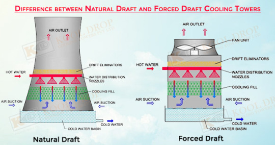
The primary task of a cooling tower is to reject heat into the atmosphere.
Cooling tower types:
Cooling towers falls into two main categories: (1) Natural Draft and (2) Mechanical draft.
Natural Draft Towers:
Natural draft towers use very large concrete chimney to introduce air through the media. Due to the large size of these towers, they are generally used for water flow rates above 45,000 m3.hr. These types of towers are used only by utility power plants.
Mechanical Draft Towers:
Mechanical draft towers utilize fans to force or suck air through circulated water. The water falls downwards over fill surfaces which help increase the contact time between the water and the air - this helps maximise heat transfer between the two. Cooling rates of Mechanical Draft Towers depends upon their fan diameter and speed of operation.
Mechanical draft cooling towers:
Mechanical draft towers are available in the following airflow arrangements:
Counter flow induced draft.
Counter flow forced draft.
Cross flow induced draft.
Components of cooling towers:
The basic components of evoparative tower are: Frame and Casing, Fill, Cold water basin, Drift eliminator, Air inlet, Louvers, Nozzles, and Fans.
0 notes
Text
COOLING TOWERS
The primary task of a cooling tower is to reject heat into the atmosphere.
Cooling tower types:
Cooling towers falls into two main categories: (1) Natural Draft and (2) Mechanical draft.
Natural Draft Towers:
Natural draft towers use very large concrete chimney to introduce air through the media. Due to the large size of these towers, they are generally used for water flow rates above 45,000 m3.hr. These types of towers are used only by utility power plants.
Mechanical Draft Towers:
Mechanical draft towers utilize fans to force or suck air through circulated water. The water falls downwards over fill surfaces which help increase the contact time between the water and the air - this helps maximise heat transfer between the two. Cooling rates of Mechanical Draft Towers depends upon their fan diameter and speed of operation.
Mechanical draft cooling towers:
Mechanical draft towers are available in the following airflow arrangements:
Counter flow induced draft.
Counter flow forced draft.
Cross flow induced draft.
Components of cooling towers:
The basic components of evoparative tower are: Frame and Casing, Fill, Cold water basin, Drift eliminator, Air inlet, Louvers, Nozzles, and Fans.
via Blogger https://ift.tt/2GBmNys
0 notes
Link
Pneumatic conveyors are used to transport dry, free-flowing, grannular material in suspension within a pipe or duct. This is done by the use of a high-velocity air stream or by the energy of expanding compresses air within a comparatively dense column of fluidized or aerated material.
Principal uses of pneumatic conveyors are
(1) Dust collection,
(2) Conveying soft materials such as flake or tow, and
(3) Conveying hard materials such as fly ash, cement, and saw dust.
The primary advantages of pneumatic conveyor systems are the flexibility of piping configurations and the fact that they greatly reduce the explosion hazard. With exception of the primary driver, there are no moving parts that can fail or cause injury. However, when they are used to transport explosive materials, there is still some potencial for static charge buildup that could cause an explosion.
Configuration:
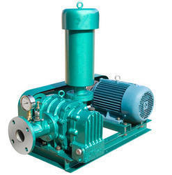
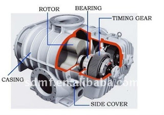
A typical pneumatic conveyor consists of Schedule -40 pipe or ductwork, which provides the primary flow path used to transport the conveyed material. Motive power is provided by the primary drive, which can be a fn, fluidizer, or positive-displacement compressor.
Performance:
Pneumatic conveyor performance is determined by the following factors:
(1) Primary-driver output,
(2) Internal surface of the piping or ductwork, and
(3) Condition of the transported material.
Specific factors affecting performance include motive power, fricition loss, and flow restricitons.
Motive Power:
The motive power is provided by the primary drive, which generates the air velocity to transport material within a pneumatic conveyor system. due to this the efficiency of the system is depends on the primary drive's operating condition.
Friction Loss:
Friction loss within a pneumatic conveyor system is a primary source of efficiency loss. To reduce these losses the piping or duct work must be properly size is used.
Flow Restrictions:
One of the disadvantage of this system is their potencial for blockage. To reduce this the inside surfaces must be clean and free of protrusions or other defects that can restrict or interrupt the flow of material. In some cases when the system is shutdown or the velocity drops below the minimum required to keep the transported material suspended, the product will settle in the duct, this settled material cause reduce flow and eventually result in a complete blockage of the system.
Installation:
All piping and ductwork should be as stright and short as possible. Bends should have a radius of atleast three times the diameter of the pipe or ductwork. The diameter should be selected to minimize friction losses and maintain enough velocity to prevent settling of the conveyed material. Brach lines should be configured to match as closely as possible the primary flow direction and avoid 90-degree angles to the main line. The area of the main conveyor line at any point along its run should be 20-25% greater than the sum of all its branch lines.
Clean-outs and drop-legs, should be installed at regular intervals throughout the system to permit foreign materials to drop out of the conveyed mateerial. It is must to install adequate clean-out systems near flow restrictions and at the end of the conveyor system.
Operating Methods:
Pneumatic conveyor systems must be operated properly to prevent chronic problems. The primary concern being to maintain constant flow and velocity.
Constant velocity can be maintained only when the system is operated within its performance envelope and when regular clean-out is part of the normal operating practice. In addition, the primary driver must be in good operating condition. Any deviation in the primary driver's efficiency reduces the velocity and can result in partial or complete blockage.
The entire pneumatic conveyor system should be completely evacuated before shutdown to prevent material from settling in the piping or ductwork. In non-continuous applications, the conveyor system should be operated until all material within the conveyor's piping is transported to its final destination. Material that is allowed to settle will compact and partially block the piping. Over time, this will cause a total blockage of the conveyor system.
0 notes
Text
PNEUMATIC CONVEYORS
Pneumatic conveyors are used to transport dry, free-flowing, grannular material in suspension within a pipe or duct. This is done by the use of a high-velocity air stream or by the energy of expanding compresses air within a comparatively dense column of fluidized or aerated material.
Principal uses of pneumatic conveyors are
(1) Dust collection,
(2) Conveying soft materials such as flake or tow, and
(3) Conveying hard materials such as fly ash, cement, and saw dust.
The primary advantages of pneumatic conveyor systems are the flexibility of piping configurations and the fact that they greatly reduce the explosion hazard. With exception of the primary driver, there are no moving parts that can fail or cause injury. However, when they are used to transport explosive materials, there is still some potencial for static charge buildup that could cause an explosion.
Configuration:
A typical pneumatic conveyor consists of Schedule -40 pipe or ductwork, which provides the primary flow path used to transport the conveyed material. Motive power is provided by the primary drive, which can be a fn, fluidizer, or positive-displacement compressor.
Performance:
Pneumatic conveyor performance is determined by the following factors:
(1) Primary-driver output,
(2) Internal surface of the piping or ductwork, and
(3) Condition of the transported material.
Specific factors affecting performance include motive power, fricition loss, and flow restricitons.
Motive Power:
The motive power is provided by the primary drive, which generates the air velocity to transport material within a pneumatic conveyor system. due to this the efficiency of the system is depends on the primary drive's operating condition.
Friction Loss:
Friction loss within a pneumatic conveyor system is a primary source of efficiency loss. To reduce these losses the piping or duct work must be properly size is used.
Flow Restrictions:
One of the disadvantage of this system is their potencial for blockage. To reduce this the inside surfaces must be clean and free of protrusions or other defects that can restrict or interrupt the flow of material. In some cases when the system is shutdown or the velocity drops below the minimum required to keep the transported material suspended, the product will settle in the duct, this settled material cause reduce flow and eventually result in a complete blockage of the system.
Installation:
All piping and ductwork should be as stright and short as possible. Bends should have a radius of atleast three times the diameter of the pipe or ductwork. The diameter should be selected to minimize friction losses and maintain enough velocity to prevent settling of the conveyed material. Brach lines should be configured to match as closely as possible the primary flow direction and avoid 90-degree angles to the main line. The area of the main conveyor line at any point along its run should be 20-25% greater than the sum of all its branch lines.
Clean-outs and drop-legs, should be installed at regular intervals throughout the system to permit foreign materials to drop out of the conveyed mateerial. It is must to install adequate clean-out systems near flow restrictions and at the end of the conveyor system.
Operating Methods:
Pneumatic conveyor systems must be operated properly to prevent chronic problems. The primary concern being to maintain constant flow and velocity.
Constant velocity can be maintained only when the system is operated within its performance envelope and when regular clean-out is part of the normal operating practice. In addition, the primary driver must be in good operating condition. Any deviation in the primary driver's efficiency reduces the velocity and can result in partial or complete blockage.
The entire pneumatic conveyor system should be completely evacuated before shutdown to prevent material from settling in the piping or ductwork. In non-continuous applications, the conveyor system should be operated until all material within the conveyor's piping is transported to its final destination. Material that is allowed to settle will compact and partially block the piping. Over time, this will cause a total blockage of the conveyor system.

via Blogger http://bit.ly/2IJy008
0 notes
Text
Conveyor Systems
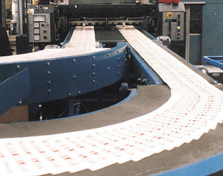
A Conveyor system is a standard piece of mechanical material handling equipment or assemblie, that moves materials or packages from one location to a different location with minimal effort over a fixed path.

Image Source: Wikipedia
They typically contains frames that support rollers, wheels or belts and that they could also be motor powered or manual devices. Conveyors are particularly helpful in applications involving the transportation of heavy or bulky materials like gravel or aggrregate. They are extremely popular in the material handling and packaging industries due to efficient and fast transportation of materials.
They also include moving belts that used in belt conveyors, bucket and vertical conveyors that raise material, vibrating conveyors that use vibrating motion to maneuver material, and overhead conveyors from which things suspend throughout transport. Different sorts include screw conveyors for moving liquid or material consisting of small grains, chute conveyors are located on sleek surfaces and gravity, and drag or tow conveyors that use cables to pull objects on. Walking beam conveyors move objects by forward sweep mechanism to planned positions for manufacturing operations.

Image Source: http://bit.ly/2WKBpFC
Types of conveyor systems
Coming to types of conveyors, there are many alternative varieties of conveyors we are able to notice. First of all companies those who want to use conveyors should be able to notice their wants. Some of the foremost common things ought to be considered before installation are mentioned below.
Product type being handled: Unit load or Bulk load
Product dimention: Length, breadth and height
Product Variability
Surrounding environment i.e., It's location : Overhead, on-floor, or in-floor
Whether or not lots will accumulate on the conveyor
Type of path: Horizantal, Declined or Inclined manner
The verity of conveyors is infinite, but the two major classifications used in typical plants are Pneumatic and Mechanical.
Note: The power requirement of a Pneumatic conveyor system are much greater than for a mechanical conveyor of equal capacity.
What is meant by conveyor?
Different types of conveyors:
Mechanical Conveyors: 1. Chute conveyor
2. Wheel conveyor
3. Rollor conveyor
a. Gravity Roller conveyor
b. Live powered roller conveyor
4. Chain conveyor
5. Slat conveyor
6. Belt conveyor
a. Magnetic belt conveyor
b. Troughed belt conveyor
c. Slider bed
d. Roller bed
e. Horizontal belt conveyor
f. Inclined and declined conveyor
g. Brake and meter conveyor
h. Wire mesh belt conveyor
i. Portable conveyor
j. Metal piano hinge conveyor
7. Bucket conveyor
8. Vibrating conveyor
9. Screw conveyor
10. Tow conveyor
11. Trolley conveyor
12. Monorail conveyor
13.
Pneumatic Conveyors:
via Blogger http://bit.ly/2Zq8Ha6
0 notes
Text
Types of conveyor systems
Coming to types of conveyors, there are many alternative varieties of conveyors we are able to notice. First of all companies those who want to use conveyors should be able to notice their wants. Some of the foremost common things ought to be considered before installation are mentioned below.
Product type being handled: Unit load or Bulk load
Product dimention: Length, bredth and height
Product Variability
Surrounding environment i.e., It's location : Overhead, on-floor, or in-floor
Whether or not lots will accumulate on the conveyor
Type of path: Horizantal, Declined or Inclined manner
Different types of conveyors:
The verity of conveyors is infinite, but the two major classifications used in typical plants are Pneumatic and Mechanical.
Note: The power requirement of a Pneumatic conveyor system are much greater than for a mechanical conveyor of equal capacity.
Mechanical Conveyors: 1. Chute conveyor
2. Wheel conveyor
3. Rollor conveyor
a. Gravity Roller conveyor
b. Live powered roller conveyor
4. Chain conveyor
5. Slat conveyor
6. Belt conveyor
a. Magnetic belt conveyor
b. Troughed belt conveyor
c. Slider bed
d. Roller bed
e. Horizantal belt conveyor
f. Inclined and declined conveyor
g. Brake and meter conveyor
h. Wire mesh belt conveyor
i. Portable conveyor
j. Metal piano hinge conveyor
7. Bucket conveyor
8. Vibrating conveyor
9. Screw conveyor
10. Tow conveyor
11. Trolley conveyor
12. Monorail conveyor Pneumatic Conveyors:
via Blogger http://bit.ly/2F9dSDD
0 notes
Link
A Conveyor system is a standard piece of mechanical material handling equipment or assemblie, that moves materials or packages from one location to a different location with minimal effort over a fixed path.

Image Source: Wikipedia
They typically contains frames that support rollers, wheels or belts and that they could also be motor powered or manual devices. Conveyors are particularly helpful in applications involving the transportation of heavy or bulky materials like gravel or aggrregate. They are extremely popular in the material handling and packaging industries due to efficient and fast transportation of materials.
They also include moving belts that used in belt conveyors, bucket and vertical conveyors that raise material, vibrating conveyors that use vibrating motion to maneuver material, and overhead conveyors from which things suspend throughout transport. Different sorts include screw conveyors for moving liquid or material consisting of small grains, chute conveyors are located on sleek surfaces and gravity, and drag or tow conveyors that use cables to pull objects on. Walking beam conveyors move objects by forward sweep mechanism to planned positions for manufacturing operations.

Image Source: http://bit.ly/2WKBpFC
Types of conveyor systems
Coming to types of conveyors, there are many alternative varieties of conveyors we are able to notice. First of all companies those who want to use conveyors should be able to notice their wants. Some of the foremost common things ought to be considered before installation are mentioned below.
Product type being handled: Unit load or Bulk load
Product dimention: Length, breadth and height
Product Variability
Surrounding environment i.e., It's location : Overhead, on-floor, or in-floor
Whether or not lots will accumulate on the conveyor
Type of path: Horizantal, Declined or Inclined manner
The verity of conveyors is infinite, but the two major classifications used in typical plants are Pneumatic and Mechanical.
Note: The power requirement of a Pneumatic conveyor system are much greater than for a mechanical conveyor of equal capacity.
What is meant by conveyor?
Different types of conveyors:
Mechanical Conveyors: 1. Chute conveyor
2. Wheel conveyor
3. Rollor conveyor
a. Gravity Roller conveyor
b. Live powered roller conveyor
4. Chain conveyor
5. Slat conveyor
6. Belt conveyor
a. Magnetic belt conveyor
b. Troughed belt conveyor
c. Slider bed
d. Roller bed
e. Horizontal belt conveyor
f. Inclined and declined conveyor
g. Brake and meter conveyor
h. Wire mesh belt conveyor
i. Portable conveyor
j. Metal piano hinge conveyor
7. Bucket conveyor
8. Vibrating conveyor
9. Screw conveyor
10. Tow conveyor
11. Trolley conveyor
12. Monorail conveyor
13.
Pneumatic Conveyors:
0 notes
Link
Coming to types of conveyors, there are many alternative varieties of conveyors we are able to notice. First of all companies those who want to use conveyors should be able to notice their wants. Some of the foremost common things ought to be considered before installation are mentioned below.
Product type being handled: Unit load or Bulk load
Product dimention: Length, bredth and height
Product Variability
Surrounding environment i.e., It's location : Overhead, on-floor, or in-floor
Whether or not lots will accumulate on the conveyor
Type of path: Horizantal, Declined or Inclined manner
Different types of conveyors:
The verity of conveyors is infinite, but the two major classifications used in typical plants are Pneumatic and Mechanical.
Note: The power requirement of a Pneumatic conveyor system are much greater than for a mechanical conveyor of equal capacity.
Mechanical Conveyors: 1. Chute conveyor
2. Wheel conveyor
3. Rollor conveyor
a. Gravity Roller conveyor
b. Live powered roller conveyor
4. Chain conveyor
5. Slat conveyor
6. Belt conveyor
a. Magnetic belt conveyor
b. Troughed belt conveyor
c. Slider bed
d. Roller bed
e. Horizantal belt conveyor
f. Inclined and declined conveyor
g. Brake and meter conveyor
h. Wire mesh belt conveyor
i. Portable conveyor
j. Metal piano hinge conveyor
7. Bucket conveyor
8. Vibrating conveyor
9. Screw conveyor
10. Tow conveyor
11. Trolley conveyor
12. Monorail conveyor Pneumatic Conveyors:
0 notes

Photo

what is meant by conveyor? or Conveyor system? http://bit.ly/2WJt68o
0 notes
Link
A Conveyor system is a standard piece of mechanical material handling equipment or assemblie, that moves materials or packages from one location to a different location with minimal effort over a fixed path.

Image source: Wikipedia
They typically contains frames that support rollers, wheels or belts and that they could also be motor powered or manual devices. Conveyors are particularly helpful in applications involving the transportation of heavy or bulky materials like gravel or aggrregate. They are extremely popular in the material handling and packaging industries due to efficient and fast transportation of materials.
They also include moving belts that used in belt conveyors, bucket and vertical conveyors that raise material, vibrating conveyors that use vibrating motion to maneuver material, and overhead conveyors from which things suspend throughout transport. Different sorts include screw conveyors for moving liquid or material consisting of small grains, chute conveyors are located on sleek surfaces and gravity, and drag or tow conveyors that use cables to pull objects on. Walking beam conveyors move objects by forward sweep mechanism to planned positions for manufacturing operations. The verity of conveyors is infinite, but the two major classifications used in typical plants are Pneumatic and Mechanical. Note: The power requirement of a Pneumatic conveyor system are much greater than for a mechanical conveyor of equal capacity.
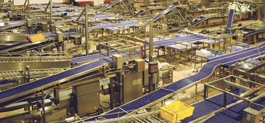
Image Source: http://bit.ly/2WKBpFC
0 notes
Text
what is meant by conveyor? or Conveyor system?
A Conveyor system is a standard piece of mechanical material handling equipment or assemblie, that moves materials or packages from one location to a different location with minimal effort over a fixed path.

Image source: Wikipedia
They typically contains frames that support rollers, wheels or belts and that they could also be motor powered or manual devices. Conveyors are particularly helpful in applications involving the transportation of heavy or bulky materials like gravel or aggrregate. They are extremely popular in the material handling and packaging industries due to efficient and fast transportation of materials.
They also include moving belts that used in belt conveyors, bucket and vertical conveyors that raise material, vibrating conveyors that use vibrating motion to maneuver material, and overhead conveyors from which things suspend throughout transport. Different sorts include screw conveyors for moving liquid or material consisting of small grains, chute conveyors are located on sleek surfaces and gravity, and drag or tow conveyors that use cables to pull objects on. Walking beam conveyors move objects by forward sweep mechanism to planned positions for manufacturing operations. The verity of conveyors is infinite, but the two major classifications used in typical plants are Pneumatic and Mechanical. Note: The power requirement of a Pneumatic conveyor system are much greater than for a mechanical conveyor of equal capacity.

Image Source: http://bit.ly/2WKBpFC
via Blogger http://bit.ly/2WJt68o
0 notes
Link
The paper machine headbox is an equipment that supply low consistancy pulp (stock) uniformly into the forming section. The formation and uniformity if the final paper product depends on the dispersion of fibre and fillers. Machine headbox had major effect on paper qualities. There are different types of headboxes are present, all are not suitable for for all grades and types of paper and machine speed. Awell constructed headbox will give good quality paper. So the design headbox should be proper. The headbox is also called as "Stuffbox" or "Flowbox".
Paper machine headbox types:
In general the Headbox is catogarised into 3 major types, as Open type, Air padded type, and Hydraulic type.
Hydraulic type of headbox is designed for high speed paper machines (speed above 350 m/min). Whereas open type open type headbox is designed for low speed paper machine. In Hydraulic and Air padded headedbox, the discharge velocity from the slice depends on the feeding pump. For this reason they are generally called as "Pressurised Headbox". The hydraulic headbox has no air pad, it is fully closed.
Incase of air padded headbox pond level is maintained. Above the pond level it containes pressuried air. To maintain this air pressure we use headbox blowers. The stock level is known as Head, which is controlled by air pressure. The head determines the slice jet velocity or speed. These type of headboxes contains two or three "Holey rolls or rectifier rolls", and a "headbox shower".
Multi layered headbox is available for making Tissue paper and light weight container board. Foe each layer it has different furnish compositions and delivary system.
Headbox jet velocity calculation:
Jet velocity is the very important factor in the manufacturing of high quality paper. We have to maintain jet-to-wire velocity ratio; 0.97 to 1.03. The headbox jet velocity can be calculated from Bernoulli's equation:
V2=2gh
Headbox Functions:
The headbox serves many functions among them the following three functions are very important in the paper production process. If the headbox doesnot perform these three functions acceptbly, the quality of the paper produced will be greatly diminished.
1. Spread the low consistancy stock uniformly along the width of the wire.
2. Accelerate the stock and maintain constant velocity according to the paper machine operating speed.
3. Create control turbulance and suspend the pulp fibres throughout the out going slurry to eliminate fibre gathering.
Parts of Headbox:
The Headbox generally contains following parts:
1. Diffuser
2. Compressor line
3. Holly rolls
4. Rotating shower
5. Bottom lip
6. Top lip
Holey roll or Rectifier roll or evenor roll:
These rolls are genreally 2 to 3 present in headbox. These rolls are used for controlling both even outflow irregularities and to create turbulance to keep the fibre dispersed up to the slice opening. Normally hole diameter is 3 to 4 cm.
Rotating shower:
This shower is used for continous headbox cleaning purpose and also consistancy maintenance.
Paper machine headbox slice:
The paper machine headbox slice is a full width nozzle with a completely adjustable opening to give the desired rate of flow. The slice contains two lips; Top lip and Bottom lip. Among them bottom lip is adjustable; we can up or down or move sides also by hand operated or motor driven. On the otherhand top lip is fixed. The distance between the top lips are called Slice opening. The slice opening controls the stock jet velocity which is very importnat for the paper fromation.
The slice spindle contains a gearbox, connecting rod, Spindle, and hook which lifts bottom lip.
0 notes
Text
PAPER MACHINE HEADBOX
The paper machine headbox is an equipment that supply low consistancy pulp (stock) uniformly into the forming section. The formation and uniformity if the final paper product depends on the dispersion of fibre and fillers. Machine headbox had major effect on paper qualities. There are different types of headboxes are present, all are not suitable for for all grades and types of paper and machine speed. Awell constructed headbox will give good quality paper. So the design headbox should be proper. The headbox is also called as "Stuffbox" or "Flowbox".
Paper machine headbox types:
In general the Headbox is catogarised into 3 major types, as Open type, Air padded type, and Hydraulic type.
Hydraulic type of headbox is designed for high speed paper machines (speed above 350 m/min). Whereas open type open type headbox is designed for low speed paper machine. In Hydraulic and Air padded headedbox, the discharge velocity from the slice depends on the feeding pump. For this reason they are generally called as "Pressurised Headbox". The hydraulic headbox has no air pad, it is fully closed.
Incase of air padded headbox pond level is maintained. Above the pond level it containes pressuried air. To maintain this air pressure we use headbox blowers. The stock level is known as Head, which is controlled by air pressure. The head determines the slice jet velocity or speed. These type of headboxes contains two or three "Holey rolls or rectifier rolls", and a "headbox shower".
Multi layered headbox is available for making Tissue paper and light weight container board. Foe each layer it has different furnish compositions and delivary system.
Headbox jet velocity calculation:
Jet velocity is the very important factor in the manufacturing of high quality paper. We have to maintain jet-to-wire velocity ratio; 0.97 to 1.03. The headbox jet velocity can be calculated from Bernoulli's equation:
V2=2gh
Headbox Functions:
The headbox serves many functions among them the following three functions are very important in the paper production process. If the headbox doesnot perform these three functions acceptbly, the quality of the paper produced will be greatly diminished.
1. Spread the low consistancy stock uniformly along the width of the wire.
2. Accelerate the stock and maintain constant velocity according to the paper machine operating speed.
3. Create control turbulance and suspend the pulp fibres throughout the out going slurry to eliminate fibre gathering.
Parts of Headbox:
The Headbox generally contains following parts:
1. Diffuser
2. Compressor line
3. Holly rolls
4. Rotating shower
5. Bottom lip
6. Top lip
Holey roll or Rectifier roll or evenor roll:
These rolls are genreally 2 to 3 present in headbox. These rolls are used for controlling both even outflow irregularities and to create turbulance to keep the fibre dispersed up to the slice opening. Normally hole diameter is 3 to 4 cm.
Rotating shower:
This shower is used for continous headbox cleaning purpose and also consistancy maintenance.
Paper machine headbox slice:
The paper machine headbox slice is a full width nozzle with a completely adjustable opening to give the desired rate of flow. The slice contains two lips; Top lip and Bottom lip. Among them bottom lip is adjustable; we can up or down or move sides also by hand operated or motor driven. On the otherhand top lip is fixed. The distance between the top lips are called Slice opening. The slice opening controls the stock jet velocity which is very importnat for the paper fromation.
The slice spindle contains a gearbox, connecting rod, Spindle, and hook which lifts bottom lip.
via Blogger http://bit.ly/2HtOeLr
0 notes