
Select high quality Ptfe Machine products varied in Type from sukoptfe.com.Gaskets Press Machine,PTFE Hose Machine,PTFE Rod Extruder,PTFE Tube Extruder,Various PTFE/Teflon...www.sukoptfe.com
Don't wanna be here? Send us removal request.
Statistics
We looked inside some of the posts by sukoptfe-blog and here's what we found interesting.
Average Info
Notes Per Post
0
Likes Per Post
0
Reblog Per Post
0
Reply Per Post
0
Time Between Posts
1 day
Number of Posts By Type
Text
13
Video
4
Last Seen Tumblr Blogs


Fun Fact
Hackers stole 65M passwords from Tumblr in 2013.
Text
Chemical recycling of waste polymer materials
Chemical cycle is one of the important methods of polymer material cycle, which refers to the degradation reaction of polymers under the action of heat and chemical reagents to form low-molecular weight products, which can be further utilized, such as monomer repolymerization, oil products can be further processed. At present, the main methods of chemical cycle are chemical degradation. Chemical degradation can be divided into depolymerization, pyrolysis, hydrogenation and gasification.
The present situation of chemical cycle development of polymer materials
1. Step - by - step polymer material
The progressive polymer materials mainly include polyester and polyurethane, which are represented by polyethylene terephthalate. Mainly used for film, fiber and fabric, beverage bottle, etc. Waste materials can react with polyols in the presence of catalysts and the products can be condensed with unsaturated polyacids to make unsaturated polyresin. Different esters can be obtained by alcoholysis with different alcohols, either as monomers or as plasticizers. PET can be hydrolyzed under acidic or alkaline conditions. It can be hydrolyzed under normal pressure in strong acid (such as sulfuric acid and nitric acid) medium. The hydrolysis rate is fast. If it is hydrolyzed in an aqueous solution of alkaline (such as NaOH), 3-sh should be reacted at 21 2500C and 1.4-2.0mpa. After the reaction, TPAO weak alkali (such as hydrogen and oxygen) can be precipitated, and can also be used to hydrolyze PET waste to obtain monomer. Saponification reaction under atmospheric pressure has been applied in silver and TPAO polyurethane is from recycled PET film condensation polymer materials, can be hydrolyzed into the pluralistic alcohol and amine, with a special extruder hydrolysis, dibasic acid can be obtained by the purification of the product and diamine, diamine and reaction with phosgene, preparation of diisocyanate, used for foam production. But the cost of this process is large and the recovery benefit is not high. PU alcoholysis is a widely used method at present. PU waste materials can be alcoholyzed to obtain polyol mixture, which cannot be separated effectively at present, but this product can be used as a component in the manufacture of foam plastics and elastomers.
2. Additive polymer material
Polystyrene (ps) in addition to used as paint, binder, but also used to crack styrene ps under the action of heat can be cracked into styrene, the yield of 65%, above. Japanese scientists have cracked PS in solvent method, decomposed it at 400 to 500 ℃ for 1 20min, and the condensate obtained can be distilled into styrene with a purity of 96%.High purity styrene can be obtained by fractionation using metal oxide as catalyst in melting state (>350 ℃).In addition, lead alloy is used as heating medium to crack ps. Under the action of appropriate catalyst or irradiation, polyolefin can undergo chemical reactions to form materials with good performance, such as polyethylene (PE), which can be crosslinked with crosslinking agents (such as peroxides) to produce PE materials with good performance. Waste polyolefin can be chlorinated, and the chlorinated polyolefin can be used in binders and coatings. In addition, polymer polymerization to make oil is a common cycle method.
3. Hybrid polymers and composites
A common method of making use of a variety of polymer mixtures is cracking them to make oil. The mixture is cracked at high temperatures to produce gas and oil, which can be used as fuel or refined directly at the refinery. Chemical plants have high requirements on the organochlorine content of oil, generally no more than 10 * 10-6. However, the organochlorine content of oil obtained from cracking of plastic mixture can reach (50 to 200) * 10-6, so it is very important to dehalogen before cracking or during cracking. In addition, waste plastics often contain heavy metal element compounds, cracking oil refining to consider the poisoning of the catalyst. Most of the resins of composite materials are thermosetting resins such as unsaturated polyvinegar resin, epoxy resin and phenolic resin, etc. The waste materials of composite materials are not only used as powder filler, combustion to take heat and chemical auxiliary fuel, but also used for cracking and recycling oil products and raw materials. For example, after the decomposition of glass fiber reinforced plastics at 380 ℃ at atmospheric pressure of 50 ℃, the further decomposition at 450 ℃ and 550 ℃ can obtain oil products. Due to the large amount of residue, a special decomposition furnace needs to be designed to complete the pyrolysis process, and the research work is still under way. Another example is the pyrolysis of phenolic resin in the experimental vulcanization bed (722 ℃), the products include aliphatic hydrocarbon (mass fraction is 5 · 24%), phenol (8, 25%), carbon black (42).2%), gas (24, 3%), etc.
Chemical cycle process and equipment
1. Reaction Still
Reaction kettle is a common chemical equipment for chemical circulation, and its matching equipment is condenser, storage tank, distillation tower, etc. The products of raw materials (such as polyolefin) degraded in the reaction kettle can be monomer, chemical raw materials, etc., such as PET pyrolysis and then polymerization into PET, or unsaturated polyvinegar resin can be produced. According to the demand, the reactor can be designed into a tank reactor to facilitate heating and slag removal. The reactor can also be designed as a tubular reactor, which can increase the cracking temperature, shorten the time, and continuously crack, suitable for the cracking of ps, PMMA and other polymers.
2. Fluidized bed reactor
Fluidized bed reactor is a kind of bed reactor. W. kanaminsky et al., Germany, used propane combustion to heat carrier gas or water vapor, and used heater to heat sand and carrier gas to 500 ° c at 00 ° c. The carrier gas should be enough to promote sand fluidization in the reactor. The polymer is squeezed into the fluidized bed by the extruder, and the polymer material is cracked in the fluidized bed. The resulting gas and carrier gas are separated by condensation and separation, and the pyrolysis products are obtained. Fluidized bed cracking apparatus has the advantages of fast heating, high efficiency, even cracking temperature and closed system. Cracking reaction is best carried out under inert carrier gas. If air is used as carrier gas, the product is easy to be oxidized and the thermal energy of the obtained oil is 10700 lower.
3. Extrusion cracking equipment
Extrusion cracking equipment is composed of two extruders in series. The first extruder has a vent hole. The waste polymer materials were cracked at low temperature on the first extruder. The main purpose was to remove HCI from the waste materials. The intermediate products of cracking are then entered into the second extruder for high-temperature cracking, which turns the polymer into a low-molecular compound or oil or gas. After separation, HCG cracking reaction can be carried out continuously, which can be decomposed mechanically and thermally. In addition, new devices are being researched and developed.


0 notes
Text
Reclamation and Re-resource Of Fiber Reinforced Polymer Based Composites
1. Mposition and recycling of fiber reinforced resin matrix composites
1.1 Thermoplastic resin base
Fiber reinforced thermal plastic recycle and pure thermoplastics (FRTP) recycling some similar, but there in the FRTP enhancement phase, and enhance the phase structure and distribution characteristics of greater influence on the performance of the materials, so its recovery processing is much more difficult than pure thermoplastics, and recovery processing after the change of its mechanical properties is also a focus of concern. In the past, high industrial costs and cumbersome recycling processes meant little attention was paid to recycling, resulting in the accumulation of waste fibre-reinforced plastics in factories. With the intensification of business competition, the enhancement of environmental protection awareness and the pressure of resource depletion globally, more and more factories have processed and recycled their wastes, and great progress has been made in the recycling and utilization of fiber-reinforced plastics internationally.
1.2 Thermosetting resin base
In contrast, the separation and recovery of fiber reinforced thermosetting resin matrix composites is more difficult due to the three-dimensional network structure formed after molding. According to the recovery process, there are two methods: one recovery and three recovery. Secondary recycling refers to the use of waste materials to be mechanically crushed, used as a filler for the preparation of new composite materials, or directly used to fill thermoplastics. This process only requires mechanical action and is a physical change process. The three times recovery method means that the thermosetting resin matrix is decomposed into its low molecular substance by heating it in different media or through chemical reaction, so as to achieve the separation from the reinforcing material and realize the purpose of recovery.
A granulator is used to granulate the chip molding (SMC) fragments. The glass fiber in the granule still has the basic size (the fiber length-diameter ratio is greater than the critical value) and filling into the plastic has a reinforcing effect. In addition to the mechanical recovery of unsaturated polyester SMC, thermosetting phenolics are also commonly recovered by this method. During the crushing process, the fiber is separated from the brittle epoxy resin matrix to obtain a mixture of particles and staple fibers, and then the secondary pulverized particles are recycled according to different particle sizes and fiber lengths through screening or air separation. The results showed that the mechanical properties of long fiber reinforced plastics were improved by adding recycled materials in PA6.
The decomposition of polymer materials by supercritical fluid is a new technology developed in recent years, especially in thermosetting plastics. The liquid phase consists of medium and low molecular weight organic materials, and the solid phase is fiber. The obtained fiber has no obvious difference compared with unused fiber after electron microscope observation, and there is no organic material on the fiber surface, so it can be used again as reinforcing material. Studied the decomposition and recycling of carbon fiber/phenolic composite materials, and found that in the supercritical water reaction medium system in alkaline environment, increasing temperature, prolongation of time and increasing alkali concentration would be beneficial to the decomposition of resin matrix.
2. Separation and recycling of fiber reinforced rubber matrix composites
Short fiber reinforced rubber composite (SFRC) is an important part of rubber products. The main recycling ways of waste SFRC are to produce recycled rubber and waste rubber powder. Taking tires as an example, at the end of the 20th century, the world produced more than 10,000,000 tons of waste tires every year, and our country was close to 10,000,000 tons of waste tires. In the process of producing recycled rubber from waste tires or other waste rubber products, at least 5 waste fibers were generally produced, and the output was very considerable. For environmental protection and security needs, most of the reclaimed rubber factory installed with waste fiber recycling equipment, but due to technical or economic reasons, such as waste fibers were used as the fuel burn more, make the fiber more than on attached vulcanized rubber produces a large number of our fleet and s02 gas, serious atmospheric pollution and the surrounding environment, and can make the fiber of recycling waste materials.
Fortunately, people have paid more attention to the research and application of this field. An earlier overseas for recycling waste fiber, carrying out the work are mainly concentrated in the field of building materials and rubber, synthetic fiber cord scrap filling on the coagulation of the tensile strength, impact strength and tensile strength increased, and the craft simple, the cost is not high, when used as waterproof tarpaulins, runway pavement materials, not only reduce the cost, and can improve the tensile strength and resistance to puncture strength. The experiment shows that although the waste rubber has been damaged to some extent during the regeneration process, it still has certain mechanical strength, especially synthetic fiber, which still has the characteristics of good elasticity, high abrasion resistance and excellent dielectric resistance. Although the surface of these waste fibers is coated with broken rubber residue and rubber powder, their potential utilization value can be fully developed through proper processing.

0 notes
Text
Extrusion process of PTFE insulated wire
Ptfe is one of the types of fluorine plastic, used for processing and insulation layer, as a result of ptfe in melting point 327 ℃, and higher than the melting point 360 ℃ using disposable push extrusion sintering molding methods, process is more complex, process quality control involves many factors, once the control is not good, can make the extrusion process to or appear all sorts of quality problem; Once the extrusion and sintering are not successful, it will cause the material part or all scrap, ptfe price is expensive, so it has caused a big waste. Therefore, it is necessary to control the extrusion process of ptfe reasonably, comprehensively and effectively, which is a necessary condition to ensure product quality and reduce waste.
Based on the application and processing practice of ptfe material in electric wires and cables and the practical experience, the paper gives a brief overview of ptfe insulation extrusion process, hoping to help production technicians to make correct selection and control in ptfe extrusion process.
Technological process:
1. Sieve F4 powder
Ptfe powder is the powder particles after polymerization, soft, strength is very small, when in packaging container stored easily by weight or turbulence vibration in transit in the cluster, blending uneven phenomenon, so before mixing must adopt certain specifications of the mesh screen to sieve of ptfe powder, filter out larger knot cooking starch material, the specifications of the mesh screen in 8 and 12 mesh is advisable. If the agglomeration is serious, the powder should be placed in a lower temperature, after a period of time, if the agglomeration shows signs of loosening, then screening. The powder should be stored in a low temperature environment, and should be handled gently in the process of handling, so as to avoid severe agglomeration of ptfe powder and it cannot be used. In addition, environmental hygiene should be ensured and impurities or dust should not be mixed into ptfe powder. Due to the strong electrostatic adsorption of ptfe powder, it is easy to adsorb air or small impurities and dust around, so to keep the environment clean without dust, the packaging container surface should be clean before opening the cover
2. Toner or pulp treatment
When insulation needs coloring for identification, a certain proportion of toner or slurry should be added to ptfe powder. Toner is after fine grinding of high temperature resistant organic or inorganic pigment powder, easy to absorb moisture, agglomeration, so in advance should be heated treatment, remove moisture, and screen, filter out the larger particles. Generally, 180 and 200 mesh screen specifications are appropriate. If the screen screen is smaller than 180 mesh, then the pigment particles after filtering are larger, which is not conducive to the insulation performance of the insulation layer. The screen mesh is more than 200 mesh. Although the insulation performance of insulation layer is guaranteed, it is difficult to filter. Color paste is a mixture of toner and oily liquid, toner in oily liquid suspension state, but stationary for a period of time will precipitate, so before use should be shaken and mixed, so that the precipitate toner particles evenly suspended in oily liquid for use.
3. The ingredients
Batching is an important preparation before mixing, according to the ratio of polytetrafluoroethylene powder and extrusion aid, or color powder or color paste ready, after the mixture.
There are more kinds of extruder, such as yan 20 aviation gasoline, toluene, petroleum ether, or other volatile solvent oil, organic solvent, etc., different extruder volatilization speed is different, according to the actual situation of the equipment, extrusion speed to choose the appropriate extruder. The extrusion assistant volatilizes too fast, although it can shorten the drying time and improve the extrusion speed, it requires strict operation time for the preparation before extrusion, and the preparation operation time should not be too long, otherwise the extrusion assistant of the blank will be ineffective due to excessive volatilization .Extruder is too slow to evaporate, and although there may be sufficient preparation time, the drying time must be extended or higher requirements for the equipment capacity are required. The proportion of extruder should be 18% and 23%, and should be adjusted according to the specifications of the conductor, insulation layer thickness, extrusion speed and extrusion pressure. Generally, the wire specification is larger, the insulation thickness is thicker, the extrusion speed is faster, the compression is smaller, the proportion of the extruder can be appropriately small; On the contrary, the wire specification is smaller, insulation thickness is thinner, extrusion speed is slower, compression is larger, the proportion of the extruder can be appropriately larger.
Toners cost less and are still commonly used today. Using pigments to dye, teflon insulation dispersion in toner as paste, toner and ptfe powder is dry mixing, and toner additives and relatively little, easy to cause mixing cluster, dispersion is poor, is not easy to mix, will lead to serious existence chromatism different part of insulation, so its size as small as possible when choosing toner requirements, general imported toner quality is better. In the toner mixing, should choose the pigment powder temperature tolerance above 400 ℃, otherwise after high temperature sintering (sintering temperature generally basic in 350, 400 ℃) may appear the product fading phenomenon. Generally, inorganic pigments have good high-temperature resistance, while organic pigments have poor high-temperature resistance. Therefore, the use of inorganic pigments as toner is more reliable, but its environmental protection is poor. The matching ratio of toner is generally not more than] %, in the actual production can be according to the type of toner, toner quality, color requirements, insulation layer thickness, etc.
Although the cost of color paste is high, it is conducive to the uniformity of the mixture and is an ideal choice, which can effectively ensure product quality, simple operation, high efficiency and less waste. When mixing the color paste, the color paste can be added to the extrusion aid and premixed evenly. Due to the relatively large amount of extruder, it is wet mixed with ptfe powder, so there is no problem of toner agglomeration, and the dispersion is very good, it is easy to mix evenly. The proportion of color paste is generally between 0.3% and 0.5 ‰, with 3 ‰ being the majority. Only a few special cases require the proportion of 0.5 ‰.When the insulation layer edge layer thickness is relatively thin, the proportion of color paste should be appropriately increased by 0.1%, 0.2.
4. The mixture
Mixing is to mix polytetrafluoroethylene powder with extrusion aid, or color powder or color paste evenly, to ensure that the extrusion insulation lubrication and color uniformity. In order to facilitate uniform mixing, the volume of general mixing bottle (wide mouth bottle) is appropriate to 4, 5 liters, the loading quality is about 800, 1 000 g, the loading volume accounts for about 2/3 of the mixing bottle volume is good, so there is enough space for mixing.
The natural color mixture (mainly used to extrude the insulation of radio frequency cable) does not need to add toner. When mixing, put ptfe powder into mixing bottle first. Used in to make people try not to contact with mixing bottle of bottle wall, in person to squeeze aid available clean sheet tool will gently mixing in a bottle the center of the surface of ptfe powder to bottle wall, make its surface center to form a depth of about 2, 3 c of conical hole, then people directly used in a certain proportion in the taper hole; After that, the mixing bottle shall be capped and strictly sealed to prevent the extruder from volatilizing. Firstly, the mixing bottle shall be shaken and mixed manually for no less than 5 minutes, and then the mixing bottle shall be placed on the mixing machine to swing and roll for more than 30 minutes until the mixing is even.
5. Compact
The effect of pressing (material) billet is to press loose porous polytetrafluoroethylene powder into a relatively compact material billet, eliminating the pores and air contained in it for extruding use. Generally should be in the environment of 20 ℃ above the blank pressing, will be homogenized powder slowly pour into the pressure cylinder cylinder, at the same time should ensure that the heart rod and pressure cylinder cylinder concentric, and gently shake the pressure cylinder in the material surface, and then add pressure cover on it. The pressure should be appropriate, too much or too little will affect the extrusion quality. If the pressure of the blank is too large, the extruder is easy to be overpressed, and the lubrication performance during extrusion is reduced, the extrusion pressure is increased, and the shear stress of the material is larger, leading to excessive fibrosis, which is not conducive to the stability of the outside diameter of the extrusion insulation, and the shrinkage rate of insulation sintering is larger, which is also easy to cause insulation cracking.
6. Squeeze out
The preparation work for ptfe insulation extrusion mainly includes selection of compression ratio, preheating and heating of extrusion cylinder and die, adjustment of needle gap between die sleeve and die core, charging blank, conductor inspection, conductor piercing, adjustment of thread tension, combination sealing of machine head and extrusion cylinder, etc., which will be introduced in the following.
The compression ratio of different brands of ptfe powder during extrusion is also different. the proper compression ratio should be determined according to the properties of ptfe powder to ensure the process performance and quality during extrusion. Extrusion compression ratio refers to the ratio between the annular area of the extrusion die and the annular area of the blank. Generally, extruder cylinders are divided into three sizes: small, medium and large. The diameter of small cylinder is about 38 mm, medium cylinder is about 50 mm, and large cylinder is about 65 mm.In the actual production, the specifications of the extruder cylinder should be selected according to the sectional area of the extruder insulation layer.
In order to maintain a stable temperature of the blank and facilitate the volatilization of the extruder after extrusion, the extrusion cylinder and mold should be preheated properly. The preheating temperature of the extrusion cylinder should be 30 or 40 ℃, and the preheating temperature of the mold should be 50 or 60 ℃.
The extrusion should be according to the specifications of the corresponding matching mold and according to the location of the assembly, and the mold sleeve bearing line neck population and needle tube between the distance (gap) to the appropriate position. Too large or too small clearance will affect the quality of the extruded insulation layer. If the gap is too small, the velocity of extrusion of ptfe material to the outside of the mold will be accelerated, and the material will be excessively cut, leading to excessive fibrosis, resulting in the decrease of the transverse strength of insulation layer, the product is prone to longitudinal cracking or internal cracks of insulation, and the insulation and conductor coating is not tight (there is "loose cover").The gap is too large, will make ptfe material to the outside of the mold extrusion velocity slow down, material pressure on the conductor increases, often occur extrusion instability or cause conductor compression rolling and produce "pine" problem, and the conductor can not pass through the needle plug phenomenon.

0 notes
Text
Extruder Screw Design
The single most important mechanical element of a screw extruder is the screw.The proper design of the geometry of the extruder screw is of crucial importance to the proper functioning of the extruder. If material transport instabilities occur as a result of improper screw geometry, even the most sophisticated computerized control system cannot solve the problem. Screw design is often still considered to be more of an art than a science. As a result, misconceptions about certain aspects of screw design still abound today. Since the theory of single screw extrusion is now well-developed, the design of screws for single screw extruders can be based on solid engineering principles. Thus, screw design for single screw extruders should no longer be an art, but a science based firmly on the principles of polymer processing engineering.
Unfortunately, people involved in screw design are not always up-to-date on extrusion theory. As a result, many extruder screws in use today perform considerably below maximum possible performance, solely because of improper screw design.An example is the still-common use of the square pitch extruder screw. This is ascrew with constant pitch with the pitch being equal to the diameter of the screw;this pitch corresponds to a helix angle of 17.66. It can be demonstrated quite easily that the square pitch is far from optimum with respect to melting and melt convey-ing for a number of polymers. This fact has been known since the early 1950s, yet most extruder screws in use today still use the constant square pitch design.
A factor that may have contributed to the state of affairs in screw design is that there has not been a comprehensive text dealing with screw design. The objective of this chapter is to demonstrate how extrusion theory can be used to properly design extruder screws. Hopefully, this will provide a solid foundation, based on engineering principles, from which better and more effective screw designs can be developed in the future. The principles of screw design are not only important in designing new extruder screws, but also in the analysis of processing problems of an existing extrusion line. It is important to be able to recognize whether a problem is related to poor screw design or to another part of the process. Thus, knowledge of the basic principles of screw design is important to essentially every person involved with extruders.

0 notes
Text
Development of key technology of coaxial twin screw extruder
1. Spiral groove depth
The depth of screw groove is an important parameter of the twin - screw extruder. Usually it is expressed indirectly by the ratio of screw diameter and screw root diameter. The value is an important parameter to indicate the technical level of the twin screw extruder. At present, the ratio of the external diameter of the screw to the root diameter of the screw in the latest generation (sixth generation) coaxial twin-screw extruder represented by WP of Germany is D/Di = 1.55.There are many factors limiting D/Di, in addition to the center distance of the gearbox output shaft of the driving screw, the screw itself also has a greater impact on D/Di: such as the shear resistance of the screw mandle-shaft, the torque transfer mode between the screw element and the mandle-shaft, the structure of the screw element itself, etc.
(1) The breakthrough in material selection, processing technology and heat treatment performance of mandrel makes the torque capacity of mandrel bearing greatly improved, and the length-diameter ratio of screw increases from the initial 36 to 50, or even higher.
(2) The technological breakthrough of the special gear drive system of the co-directional twin-screw extruder provides the power transmission guarantee for the torque input required by the deep groove screw under the condition of the constant center distance, making the screw D/Di goes to 1.55.
(3) The torque transfer mode between screw and mandrel is the key to realize the deep screw groove. The torque transfer between the screw element and the mandrel was initially connected by flat keys, which not only limited the deepening of the screw groove and increased the free volume of the screw, but also the strength of the flat keys could not meet the requirements of some production operations. Using multi - key torque transmission in the form of involute can greatly improve the depth of the screw groove under the same outer diameter of the screw. In recent years, while learning from foreign advanced technologies, China has made great breakthroughs in processing and manufacturing. At present, it has been able to manufacture involute spline structure with the same connection form with foreign screw, thus making great breakthroughs in the depth of screw groove.
(4) The breakthrough of element structure. The structure of the kneading block solves the key technology of manufacturing, its structure changes from the original single piece type, the assembling type to the present integral type, thus guarantees the deepening of the screw groove from the strength of the element, also makes the adjustment of the screw combination and the assembly of the screw more reliable and convenient.
To sum up, breakthroughs in the aspects of gear transmission system, shear strength of mandrel, torque transmission form of screw element and mandrel, and design and manufacture of screw element ensure the successful development of a new generation of high-speed and deep screw slot extruder.
2. New screw element
Synthetic twin screw extruder is the core part of the screw, after the advent of synthetic double screw extruder, and development of screw and screw element has always been a developer research and the main direction, screw structure from the integral development early to "building block", three thread from single head to head, later when the double structure, type of screw elements, structure and function differences. Develop self-cleaning type mixer type screw element, edge type mixer type screw element, toothed screw element, pressure regulating screw element, etc., of the twin screw extruder screw element made greater innovation, supplement and perfect, strengthen and improve the direction of the twin screw extruder mixing and plasticizing effect, dispersion, shear, pressure, and adjustable.
3. Gear box torque rating parameters
The torque grade parameter M/A3 of the gear box is an important performance indicator parameter of the coaxial twin-screw extruder. Its value represents the technical level of the coaxial twin-screw extruder and represents the torque output capacity of the gear box under a certain screw center distance. Due to the particularity of the transmission form of the coaxial twin-screw extruder, the torque of the gear is input into the gear box by a high-speed shaft. Through deceleration and torque distribution, the torque is transmitted to the twin-screw by two output shafts with limited center distance under the condition of great axial force. Therefore, the ratio parameter M/A3 between the center distance of the output shaft and the output torque has become an important symbol to measure its technical level. So the design of gear box of twin screw extruder is very difficult compared with the design and development of general gear transmission system. At present, China has made great breakthroughs in gear transmission mode, torque uniform distribution and axial force solution. The torque grade parameters of the experimental extruder have been changed from 4.Seven goes up to eight.8. It lays a good foundation for the development of high speed and high torque gear box of production extruder.
In terms of the service life of the gear box, by improving and driven by new type of multi-channel way, not only greatly improve the transmission capacity, and through the reasonable arrangement of the axis, solved the gear and thrust bearing load distribution, greatly reduced the gear drive and work process of the additional force, making long-term restricting the service life of the gear box of the anti-fatigue performance of the gear, thrust bearing system performance are greatly improved, after adopts multiplex drive, output the stress of the bearing diameter of axle direction decrease greatly, therefore, in many ways to improve the gear, the thrust bearing system, the torque distribution part of the bearing service life, Designed life up to 10 a.
4. Screw speed
Screw speed is another important parameter to measure the performance grade of the extruder with the same direction and it is an important way to improve the performance index of the extruder. It directly affects the torque grade parameters and production capacity of the equipment. The screw rotation speed increase mainly depends on the innovation and development of gear transmission system drive, the ability of the screw torque under and anti-fatigue performance, by developing a new type transmission way and optimize the innovation design, selection of key parts imported bearing, means, the strict screening of screw spindle materials and the improvement of heat treatment process, and the screw element and spindle, involute spline breakthrough made in the form of uniform stress distribution, making it possible to screw rotation speed increase, has been in a small high-speed experimental synthetic twin-screw extruder machine through industrial test.
5. Production capacity
The technical level and performance of the equipment are aimed at improving production capacity, reducing energy consumption and improving reliability. Production capacity is the main factor to evaluate the performance of a unit:
(1) improve the screw speed, the same type of production can be doubled;
(2) the use of deep screw groove screw, increase the screw free volume, improve the unit speed and unit time transport capacity;
(3) the use of twin screw and gear pump combined technical route, improve the reliability of the transmission box, reduce the axial force borne by the gear, eliminate the limit of the axial force to reduce the output of the factor, improve the output of the extruder.

0 notes
Video
youtube
PTFE Polymer Bush Automatic press molding machine 3
0 notes
Video
youtube
PTFE Polymer Bush Automatic press molding machine 2
0 notes
Video
youtube
PTFE Polymer Bush Automatic press molding machine 1
0 notes
Text
Polymer material mixing extrusion technology and complete equipment
Mixing extrusion process is the only way for polymer materials, especially plastics, to move from products to industrialization. Modern polymer materials are developing towards high-performance polymer structural materials, new polymer functional materials and general polymer materials with low cost and high performance.
High performance polymer structural materials are characterized by high specific strength, excellent corrosion resistance, abrasion resistance and easy processing, which are of great significance to the development of national economy and national security. Due to its unique functional and special type, new polymer functional materials have been widely used in the industrial fields such as ecological environment protection, information functionalization, biomedical equipment, material separation membrane, energy conversion and energy storage technology. High performance of general polymer materials and low cost of engineering plastics are still the focus of current research and development of polymer materials and an important measure to expand the application scope of general plastics and engineering plastics.
In addition to some processing properties of traditional polymer materials, the new polymer materials have many differences in physical and chemical properties. Appeared with the development of new polymeric materials, the fields of application broadening, to high polymer material mixing extrusion are also put forward higher request, the traditional mixing technology and equipment have not well some new high polymer material to meet the demand of the mixing, therefore, the development of new type mixing extrusion technology and equipment, to meet the needs of the new polymer materials to industrialization, mixing equipment BNR; at the same time, also is inevitable trend of the development of polymer processing equipment today.
1. Application of twin screw mixing extrusion technology
Modern mixing and mixing extrusion technology is to blend existing polymer materials with a variety of polymers or add other materials to optimize the combination of different materials, so as to significantly improve the material properties, or give raw materials with new properties, adding new varieties to the polymer family. In the whole plastics industry, about 60% of the plastics have to be mixed and modified to produce new materials. Most of these complex processing processes are completed in the mixing equipment represented by the twin screw extruder. Using the same direction twin screw to mix extrusion has the following advantages:
(1) excellent mixing and plasticizing performance, which can fully guarantee the dispersion uniformity and performance uniformity of various materials after mixing, and is suitable for complex operations such as filling, blending, glass fiber reinforcement, reactive extrusion and volatile removal of various resins and plastics.
(2) cylinder and screw can realize "building block" combination, so as to achieve multi-purpose, multi-function.
(3) screw meshing, self-cleaning effect is good; The material achieves superior surface renewal effect and excellent exhaust performance, which can eliminate the gas or monomer generated in the mixing and plasticizing process.
(4) high screw speed, large production capacity, low power consumption per unit production, obvious energy saving effect.
Based on the above advantages, the co-directional twin-screw mixing extrusion technology has an irreplaceable advantage in polymer material processing equipment and occupies a leading position in polymer material modification production.
At present, the new type twin-screw compounding and the latest application of extrusion technology is mainly manifested in the following aspects: the preparation of nanometer material modification is high polymer material rigid Gao Ren type of low cost, high polymer alloy materials, electromagnetic shielding polymeric materials, novel polymer materials for degradable plastics, electronic packaging, new masterbatch and various functional masterbatch, etc., can also be used to new composite materials (such as wood plastic composite) the production and preparation of new materials, in addition, can also be used for polymer grafting, polycondensation of reactive extrusion. The industries involved include household appliances, automobiles, communications, electronic technology, national defense, aerospace, environmental protection, chemical industry, building materials, electric power, etc.
2. Development of new polymer material extrusion technology with twin screw
At present, the development direction of new polymer materials, which are mainly composed of nanomaterials, degradable plastics, modified asphalt and wood-plastic composite materials, centers on the industrialization of these materials, and the same-direction twin-screw extrusion technology becomes the key to realize the industrialization. Compared with ordinary polyolefin materials, these materials have great differences in material system composition, molecular structure and rheological properties.
(1) Nanomaterials are becoming a new type of materials developed by various countries in the world. From the preparation of nanometer masterbatch to the production of nanometer modified plastics, twin-screw extruder plays an irreplaceable role in the industrialization of nanometer plastics. Firstly, due to the particle size distribution of nanomaterials, the mixing extrusion and dispersion effects are required to be high. Secondly, the preparation of nanometer masterbatch for inviscid melt characteristics, low toughness, contains a large amount of gas extrusion and additives in the process of removing products of decomposition, and the traditional polymer under different state of plasticizing characteristics such as high brittleness, cooling and finished product process is different from ordinary polyolefin masterbatch process.
From mixing and plasticizing extruder to cooling and granulation, many innovative developments are needed. Therefore, the general cooling method of molten polymer cannot be adopted. The final product is produced by adopting the closed feeding mode with powder collection, adopting the new high-efficiency dense rotor element in the screw, setting buffer type exhaust mode in the cylinder, and adopting the route of belt conveying and cooling, pre-crushing and crushing in the material strip cooling and crushing.
(2) There are a lot of starch in the development of starch filled degradable plastics, double degradable plastics and whole starch thermoplastic plastics. In addition to plasticizing and mixing them, exhaust dehydration and residence time distribution in the extrusion process have become problems that need to be solved when mixing and granulating. Therefore, according to the specific materials, the appropriate host screw length-diameter ratio, exhaust location and quantity, screw structure and arrangement, additive adding mode and adding point should be selected to test and determine the configuration; At the same time, the operation technology and technology also become the key problem of the degradation plastic twin-screw extrusion. The above key technologies can be based on the existing successful experience, combined with extrusion process experiment and results analysis, finally determine the extrusion process equipment configuration.
(3) Modified asphalt has become a new direction of polymer material modification. Focusing on its application in highway construction, airport reconstruction and expansion projects, improving its temperature resistance and low temperature brittle property is the main direction of improving its application value. Because of the extensive molecular weight distribution and the structure of macromolecule, the modification of asphalt has not been much improved. Modified asphalt is very special, has both belong to the characteristics of the rubber plastic blending, but also has the content of the product post-processing, transport of twin screw extruder, mixing elements of development, such as extrusion granulation are put forward new requirements, need innovation to develop new type structure and configuration of the screw element, console, selected double screw part in all kinds of test parameters, such as screw length to diameter ratio, number and position of exhaust section, shear rate, extruding form and structure, etc.
(4) In terms of material science, WPC is a new material with great potential. It is reported that plant fiber composites have been widely used in automobile industry, construction industry, transportation industry, aviation industry and so on due to their high mechanical properties, specific hardness, specific strength, sound absorption and biodegradability. In wood fiber, wood powder mixed with resin matrix, the mixture of different methods of wood fiber in composite material obtained by dispersing uniformity of difference is very big, to realize the industrialization of the wood plastic composite this new material production is the key to the extrusion process and special structure form of extruder, the technology innovation point lies in the segmented charging ways, special screw type structure, TME and ZME element, high torque gear transmission system, large screw length to diameter ratio and D/Di = 1.55 free volume, the one-step method of twin-screw extrusion production.

0 notes
Text
Application of composite steel pipe technology
Composite steel pipe is composed of two (or more) materials combined into one through specific technological means so that it has comprehensive characteristics
Sex's new steel pipe. Since the 1960s, Japan, the United States, Germany, the United Kingdom and other countries have attached great importance to the development of composite steel pipe, composite steel pipe products in energy, shipbuilding, chemical, petroleum and machinery and other fields have been widely used. Composite steel tube processing technology mainly includes rolling, casting, extrusion, brazing, welding and so on.
1. Application range of composite steel pipe
The combination mode of two kinds of single layer materials of composite steel pipe completely depends on the application requirements and environmental characteristics. The basic steel pipe has high strength and rigidity, low price and good process performance. The covered steel pipe shall be of high hardness and have the ability to resist the corrosion of environmental medium. This layer can be in the inner layer of composite steel pipe (inner composite pipe) or in the outer layer (outer composite pipe).According to the nature of use can be divided into chemical use liquid gas pipe, oil and gas pipeline and oil well pipe, boiler, waste incinerator with multiple tube, pipe for heat exchanger, with wear resistance, corrosion resistance structure with multiple tube and architectural decoration pipe, etc., with the continuous development of composite pipe technology application, the application range of the composite pipe will be extended to more wide application fields.
2. Production method of composite steel pipe
Composite steel pipes can be divided into two types, bimetallic and double-layer, according to the combined state of the contact interfaces of the two kinds of steel pipes. The composite steel pipe with the contact interface of inner and outer layer connected to metallurgical bonding degree is called bimetallic pipe, while the contact interface of inner and outer layer only reaches mechanical connection, and the composite steel pipe with longitudinal section layer and layer freely separated is called double layer pipe. There are many different process methods to produce composite steel pipes, each of which has its own characteristics and application scope.
2.1 Hot working process
In this method, ordinary carbon steel billet is used as outer base metal, center hole is drilled, and stainless steel or nickel alloy rod is used as inner layer. Outer guarantee the physical properties of the composite pipe, the inner pipe corrosion requirements, when the bar and billet surface after the inner hole surface is clean, will bar embedded billet hole of the pipe, welding seal the ends of the tube billet, use level of low frequency induction coil to control the heating, after being heated to set temperature, in 1 600 t hot punch on the vertical hydraulic punching machine, pipe billet in circular perforation mode and axial compressed gauge circle perforation, after thermal perforated tube billet, bar and the base material to metallurgical combination. This process is used by Tubacex, a Spanish extruded steel pipe company, to produce composite steel pipes with external diameters of 60· 3 and 219 · Imm. The thickness of the corrosion resistant lining pipe is usually 10% to 0% of the total thickness of the composite pipe, usually between 2 cm and 1 cm at the minimum.
2.2 Composite steel plate welding method
This method can be used to manufacture composite steel pipes for oil and gas transmission pipelines with diameters larger than 300mm.The composite steel plate was rolled into tube billet by UO process, and then welded into longitudinal seam. The process flow of composite steel pipe produced by this method is as follows: longitudinal seam welding -- pipe expanding -- heat treatment of steel sheet i-jo forming billet.
2.3 Cold process diffusion annealing
The tube billets of different materials are made into cold-rolled or cold-drawn seamless tubes respectively. A special low-melting intermediate layer thin belt is wound around the outer side of the inner layer of tube billets. After cold drawing, high-temperature diffusion annealing is carried out. The characteristic of composite steel pipe produced by this process is that the joint boundary is very obvious and even. Due to the addition of a low melting point metal layer between the two bonding interfaces, its binding strength is relatively high, usually greater than 300MPao. The low melting point metal gasket material is usually Ni - P alloy, and its melting point temperature decreases with the increase of the content of P. The other gaskets are B (1, 4Wt%), Si (up to 9Wt %), cr(up to 30Wt%) iron - or ni-based alloys. The melting point of the gasket material must be lower than that of the outer base tube and the inner tube. The composite steel tube produced by this process can withstand bending forming, and its dimensional accuracy and surface quality can meet the standard requirements.

0 notes
Text
Application of vacuum sintering and tunnel furnace sintering
In terms of power chip assembly, the existing main problems are: the assembled chips, due to the bottom of the hollow area is more, thermal resistance is bigger, work have a lot of heat when not through the effective way to transfer to the shell, resulting in junction temperature is exorbitant, while working reliability, reduce the life of the power device, even 1 thermal breakdown failure by junction temperature is too high. In recent years, with the rapid development of the electronics industry, vacuum sintering process has been widely used, and the voidage rate, thermal resistance, connection strength and reliability have been significantly improved, which may become one of the key technologies for power chip assembly.
1. The sintering mechanism
Two different metals can form eutectic alloys in proportion at temperatures well below their respective melting points. This lower temperature is their low eutectic point. Sintering process is in between the chip and carrier (substrate) or pipe shell of a metal sheet (solder), in a certain vacuum or protective atmosphere heating to the alloy melting point make it melt, melt into liquid alloy infiltrating the whole chip welding metal and carrier surface of substrate, solder welding the weld metal and carrier with the metal physical and chemical reaction, generate a certain amount of intermetallic compound, and then, in the process of cooled to below the melting point of solder and intermetallic compound chip and carrier welded together, form good ohmic contact, thus complete the chip and carrier welding drawing.
In this paper, the tunnel sintering furnace and vacuum sintering furnace are selected respectively to weld the chip and DBC board, and the cavity rate of the two technologies is compared and analyzed through X-ray scanning, which proves that the actual effect of vacuum sintering process is better.
2. Sintering process test of tunnel furnace
The use of tunnel furnace heating, in DBC board and chip add solder piece, when the solder piece by heat melting, with the help of it on DBC board coated copper part of mutual melting and the formation of metal compound, achieve new alloy surface will chip and DBC board solidly welded together. The test results are as follows:
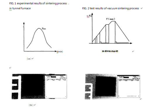
FIG. 1 (a) shows the control curve of sintering temperature in the tunnel furnace. FIG. 1 (b) is the reflow furnace in FIG. 1, which is a multi-purpose "cold wall" process welding furnace. Under the condition of observation 1 < a), X-ray scan diagram of the back side of the chip completed by the tunnel sintering furnace and benefit window are provided on the top cover of the chamber. Through it, real-time recording of each stage of the sintering process can be achieved. Then, the cavity rate of the chip after sintering can be obtained by the computer as 8, 7%.Adjust the temperature curve in time.
3. Vacuum sintering furnace process test
Internally open vacuum pump to extract air (vacuum degree 1 × 10 × 5 mbar);Then the vacuum sintering furnace used in the charge test is a kind of welding nitrogen dilution residual air with the function of rapid annealing. When the vacuum reaches its limit and there is basically no residual gas in the chamber, the filled hydrogen begins to heat up. At high temperature using hydrogen reduction, DBC board, solder and chip reduction, remove oxide, improve the penetration rate of solder. After a period of high temperature, the chip has been welded to the DBC board, but there are still many bubbles on the welding surface. After the vacuum pump is started for the third time, residual bubbles on the welding surface can be extracted as much as possible after a period of time, thus reducing the voids in the chip welding and the voids rate.
The whole process can be programmed and controlled by computer. The time, gas flow and temperature of each program section can be precisely set, and the operation is convenient. In addition, because of the use of solder sheet, do not have flux welding, so that the sintered chip can be directly sent to the next process, reducing the cleaning link, reduce production costs. The test results are as follows:
FIG. 2 (a) shows the control curve of vacuum sintering temperature. FIG. 2 (b) is the X-ray scan diagram of the back of the chip completed by vacuum sintering under the conditions of FIG. 2 (). The computer shows that the cavity rate of the chip after sintering is only 0 coincidence 2%.
4. Interpretation of result
By analyzing and comparing the results of the above two different sintering processes, it can be concluded that:
1) Sintering time: vacuum sintering time is only 1/4 of the time of tunnel sintering furnace, which greatly improves the production efficiency.
2) Sintering cavity rate: the vacuum sintering cavity rate (0· 52%) is only 6% of the tunnel sintering furnace cavity rate (8 · 7%), which reduces by 16 times and significantly improves the effective welding area.
From the comparison of the above test results, it can be seen that vacuum sintering can obtain higher quality sintering results than tunnel furnace sintering process, and the production efficiency and product reliability can be connected, so that the sintered chips can be directly sent to the next process, reducing the cleaning link and reducing the production cost. The test results are as follows:
To significant improvement; And the whole sintering process is precisely controlled by computer programming to avoid errors caused by human operation.
5. Conclusion
With the continuous improvement of semiconductor manufacturing process, vacuum sintering process and related equipment will be updated and improved day by day, gaining wider recognition and market application. However, there are many factors that affect the quality of power chip sintering, which need to be further recognized and explored.


[---This text and text source network, if there is infringement, please contact delete, thank you!---]
0 notes
Text
How to connect ptfe compensator to equipment
Application of pressure balance ptfe compensator joint in inlet and outlet pipeline of gas turbine in refinery.As shown in the figure, the bending pipe force balance ptfe compensator can not only compensate the displacement in the pipeline, but also make the smoke turbine free from the blind plate force generated by internal pressure.

Bend pipe force balance ptfe compensator is used to connect equipment to equipment, the function is to compensate the thermal expansion of pipeline between the two equipment, reduce the installation error of the force on equipment, convenient installation.The use of bending pipe force balance ptfe compensator can make the equipment free from blind plate force caused by internal pressure, improve the mechanical condition of the equipment, and make the equipment easy to be stable.
Ptfe compensator is used in the inlet and outlet of pump as a soft coupling.A universal ptfe compensator is installed on the inlet and outlet pipelines of the pump to compensate the thermal expansion of the pipeline, reduce the thrust of the pipeline thermal expansion on the pump, or absorb the vibration generated by the pump during operation.
Ptfe compensator can be used for flexible connection between storage tank and pipeline.In recent years, oil field, the bigger the depot, chemical storage tank is built, as a result of the limitation of geological conditions, the basic natural sink tank and import and export pipeline position change, causes the damage of connecting line and tank wall, so in the import and export of pipeline of storage tank installation teflon compensator to compensate displacement or metal hose.
Ptfe compensator is also widely used in iron and steel industry.Large diameter ptfe compensator and rectangular ptfe compensator are mainly used in large blast furnace and hot air furnace.For example, different types of ptfe compensators are used in the pressure relief piping system and blast furnace body system of blast furnace top equipment.A universal ptfe compensator is installed in the air supply branch pipe of the furnace body, which can not only compensate the displacement of the pipe, but also reduce the installation stress.
0 notes
Text
The forming method of large diameter plastic pipe and its research
With the development of pipeline transportation industry, the requirements for pipeline transportation capacity are becoming higher and higher, and the application of large-diameter plastic pipe is becoming more and more extensive. The research and development of large-diameter plastic pipe with high production intensity, light quality, impact resistance and corrosion resistance is one of the main development directions of pipeline transportation in the future.
In this paper, the forming method of large diameter plastic pipe, its research status, existing problems and development trend are summarized. In view of the traditional method of large diameter plastic pipe forming problem, this paper proposes a combined with increase of material manufacturing technology of traditional molding and extrusion molding technology of large diameter plastic pipe forming new technology, the polymer melt injection pile forming, namely the role of plastic melt extrusion machine pressure, jet filled by rolling pipe and keep-off device, block formed by the constraints of the space, then the rolling device and continuous screw pile under the action of tractor molding line.
Then, according to the principle of polymer melt injection and stacking technology, a large diameter plastic pipe melt injection and stacking equipment was developed. The equipment consists of extruder, pipe forming device, tractor, control system and so on. Compared with the traditional pipe molding equipment, the equipment not only don't need extrusion die head, winding mandrel, mould, also can flexible pipe molding, can Ø molding diameter 749 ~ Ø 948 mm, 30 ~ 50 mm plastic pipe wall thickness.
The main process parameters of the molding process are analyzed, including molding temperature, screw speed, traction speed, rotation speed and pitch, etc. According to the mathematical relationship between the process parameters, the process parameters set and calculated for subsequent numerical simulation analysis and experiment are required.
According to the principle of the molding process of establishing mathematical model and geometric model, using POLYFLOW software to carry on the numerical simulation, analyzes the melt velocity distribution, temperature distribution, local flow, such as law, combined with traction speed, rotating speed, cooling to finalize the design temperature, injection molding process parameters such as temperature, numerical simulation analysis, the results of experiments with theoretical guidance significance.
Finally, according to the calculated parameters and numerical simulation analysis of the conclusion, large diameter plastic pipe melt injection pile forming experiments, including on the pipe forming ring stiffness, tensile properties and impact properties and mechanical properties test, differential scanning calorimetry analysis results, analysis of the pulling speed, rotating speed, finalize the design temperature, cooling spray forming temperature and other process parameters on the molding pipe mechanical properties, the influence of the validation of numerical simulation analysis.
In addition, the mechanical properties and molding pipe by mechanical properties compared with extrusion molding pipe sizes, the results show that through the process forming of large diameter, the mechanical properties of plastic pipe is better than that of the extrusion molding, especially the impact performance, among them, the axial impact strength is 1.6 times that of extrusion molding pipe and circumferential impact strength is 2.2 times that of the extrusion molding pipe.


0 notes
Text
Teflon oven performance and matters needing attention
Teflon oven performance characteristics and product introduction:
1. Optional baking tray (only) or shelf (piece), or matching grill;
2. It can be customized according to user requirements;
3. Non-standard products can be designed and manufactured according to user requirements;
4. This product adopts digital display intelligent temperature instrument control, with self-stable PID regulation function, temperature control, easy to operate;
5. The intelligent meter has the function of time control. Users can set the working time according to their needs, and automatically stop heating at that time;
6. Door seal is made of high temperature resistant silicone rubber;
7. With direct expansion temperature controller for overtemperature protection, the equipment can operate reliably;
8. Sign oven is mainly used for drying printing ink of sign plating products, drying paint coating surface and other drying processes in various industries. It is also suitable for industrial and mining enterprises, scientific research institutions, colleges and universities, medical, biological and other laboratories.
Attention to the use of teflon oven:
1. This type of oven should work indoors and be installed smoothly;
2. The power input shall be equipped with special front-stage on-off switch and properly connected with earth wire;
3. Check the power supply, voltage and power supply wiring is correct, before power use;
4. In the new purchase and use or use for a long time, should first use low temperature baking 80-100℃ for two hours before starting to increase the temperature, to facilitate moisture leakage, enhance insulation performance and extend the life of porcelain parts;
5. The probe of the thermal sensor for temperature control of the instrument shall be inserted into the working room from the temperature measuring hole on the left side of the circuit, and shall not be inserted into the center hole of the header valve of the box to avoid affecting the use;
6. When the drying box is used for the first time, please observe it frequently to avoid overheating and damage of the workpiece, causing losses;
7. Turn off a set of heaters to reduce the heating power and prevent over temperature caused by excessive inertia when the heat habit is felt to be slightly larger;
8. Take out baking objects: do not hit the thermostat that extends into the studio to prevent damage to the thermostat and lead to failure;
9. Without "explosion-proof oven", do not bake explosive, flammable and volatile items to prevent explosion;
10. In case of failure, please call a professional electrician for maintenance.


0 notes
Text
Development and application of degradable polymer plastics
Development and application of biodegradable polymer plastics, biodegradable plastics is a kind of new type with the function of degradation of polymer materials, in use process, it has to do with the same kind of common plastic with the corresponding health and relevant application performance, and after its complete function, the material can rapidly degraded in the natural environment conditions become easy to be given environment fragments or crushed, and with the passage of time further degradation become eventually oxidation products (CO2 and water), return to nature.
Based on the environmental pollution caused by plastic waste, as well as the demand of environmental protection and human needs, it is urgent to study degradable polymer materials. In a specific time and under certain environmental conditions, the chemical structure of biodegradable plastics will change. According to the reasons for the changes in its chemical structure, biodegradable plastics can be divided into two categories: biodegradable plastics and photodegradable plastics.
1. Degradation mechanism of degradable plastics
Generally speaking, degradable plastic refers to a kind of plastic that can be decomposed into small molecules through the action of microorganisms in soil or solar radiation.It must meet the requirements of the use of products and easy to process on the basis of the basis of biodegradable properties. The nature of the action of sunlight on polymer materials is the comprehensive effect of ultraviolet light in sunlight and oxygen in air, so it is also called photooxidation degradation. Take polyolefin as an example to explain the mechanism of photooxidation degradation. In essence, photooxidation causes chain breaking or crosslinking of polymers, and some oxygen-containing functional groups, such as carboxylic acids, peroxides, ketones and alcohols, are formed in this process. Catalyst residues in polymers and initiation of peroxide and carboxyl groups introduced during processing are the main sources of degradation.
Under the action of microorganisms (mainly fungi, bacteria or algae, etc.), polymers can be eroded or metabolized to cause changes in their chemical structure and decrease in molecular weight. The mechanism of action can be mainly divided into two situations :
(1) biophysical action. That is, after the erosion of plastic products by microorganisms, biological cells growth, promote the decomposition of polymers, ionization or proton, this physical action on the polymer caused mechanical damage, the high molecular weight of the polymer into oligomer fragments, so as to achieve the purpose of physical degradation.
(2) biochemical action -- direct action of enzymes. This situation is caused by the erosion of enzymes secreted by fungi or bacteria, which leads to the splitting or oxidative disintegration of plastics, and causes the splitting or oxidative degradation of insoluble polymers into water-soluble fragments, generating new small molecular compounds (CH4, CO2 and H2O) until the final decomposition.
There are generally two hypotheses about the mechanism of biodegradation of polymer materials that lead to biodegradation. The other is an invasive cut from the end of the chain. Therefore, the structural properties of materials, such as composition, main and side chain structure, size of end groups, and presence or absence of spatial steric resistance, are the key factors affecting their degradation performance. Among them, the main chain properties have a greater impact. If the main chain of the polymer contains bonds that are easily hydrolyzed, it will be easily biodegraded. Secondly, if the backbone is flexible, the degradation rate will be relatively fast, whereas if the backbone is rigid and orderly, the degradation rate will be slow.
The biodegradability of polymer materials is reduced by branching and crosslinking. For example, the introduction of hydrophobic groups at the end of polylactic acid (PLA) molecular chain can reduce the erosion rate at the initial stage of degradation. This is because in the original degradation process, PLA's erosion mainly depends on the structure of molecular chain end, and the addition of hydrophobic groups leads to the decline of its erosion rate. In addition, some researchers have studied the chemical structure of polymers and the relative molecular weight of materials that play an important role in their degradation.
2. Development of biodegradable plastics
The development direction of biodegradable plastics in the future can be as follows:
(1) biodegradable plastics were prepared by studying the biodegradation mechanism of degradable polymers, and the block copolymerization of biodegradable plastics with existing ordinary polymers, microbial polymers and natural polymers was studied and developed.
(2) to search for microorganisms that can produce polymer plastics, explore new polymers, analyze their synthesis mechanism in detail, improve their productivity through existing methods and genetic engineering methods, and study efficient methods of cultivating microorganisms.
(3) pay attention to the control of degradation rate, develop efficient degradation promoters and stabilizers to improve the biodegradation performance of degradable plastics, reduce their cost, and expand the market application.
(4) research and establish a unified definition of degradable plastics, enrich and improve the evaluation method of biodegradation, and further understand the degradation mechanism.


0 notes
Video
youtube
PTFE teflon polymer plastic winding machine
0 notes
Text
Preparation of UHMWPE fiber
UHMWPE, also known as high-strength high-modulus polyethylene, is currently one of the world's high-performance materials. Due to its comprehensive excellent properties such as corrosion resistance, wear resistance and low density, it is currently used in military protection materials, military mechanical materials, aerospace equipment and other military fields. The development of high-performance fiber is the foundation of a country's military equipment, and the advanced material can lead to the advanced military technology, which has become an important material foundation for the construction of a powerful modern country, and occupies a decisive position in the field of military materials worldwide.
1. Properties of UHMWPE fiber
UHMWPE fiber has excellent comprehensive properties, its relative density is small, can float on water. And UHMWPE fiber is the strongest fiber in the world at present. Compared with steel, UHMWPE fiber is more than ten times stronger than high-quality steel. In addition, UHMWPE fiber also has strong corrosion resistance, chemical resistance, wear resistance and other properties, comprehensive performance, UHMWPE fiber in many important fields in China play an important role.
1.1 Excellent mechanical properties
Compared with other high-performance fibers, UHMWPE fiber density is second only to conventional PE fiber and polypropylene fiber, and it is the optimal fiber material with the smallest density among bulletproof materials. It can reduce the weight of the material and achieve a lightweight effect while ensuring better bulletproof performance.
Compared with other properties, the tensile strength of UHMWPE is only second to that of PBO and polyaryl ester fiber, and it is only 0.1 different from that of polyaryl ester fiber. It can be seen that UHMWPE has excellent tensile strength.
Compared with other fibers, the initial modulus is only second to PBO and carbon fiber, which indicates that the fiber has a relatively good resistance to damage tension and is not prone to deformation. It is a kind of characteristic fiber with ultra-high specific strength and specific modulus, which plays an important role in bulletproof material.
1.2 Electrical insulation performance
UHMWPE fiber reflectance radar wave phenomenon is very few, with high conduction efficiency, enhance the dielectric constant of composite materials. Although the dielectric constant and loss value of polyethylene are the least among other materials, UHMWPE fiber has the performance that traditional polyethylene fiber can't reach, and it has better effect than general materials, so it is the preferred material for radar radome, with high quality and light effect.
1. 3 Weather resistance and wear resistance
UHMWPE fiber has excellent weather resistance and can keep the original high performance unchanged after a long time of illumination and harsh environment. At the same time, UHMWPE fiber has higher wear resistance and bending fatigue resistance than aramid fiber in high performance materials, so the wear resistance of this fiber is better than other high performance fibers. Due to its high wear resistance and easy processing performance, it has a good application prospect in the industrial field.
1. 4 Chemical corrosion resistance
The internal structure of UHMWPE fiber is relatively tight. It is precisely because of the high crystallinity and orientation of the molecular chain inside the fiber that the fiber has a strong chemical inertia. Therefore, under the acid and base state or the high and low temperature state, the fiber can keep its original performance unchanged for a long time, and still adapt to and play its value in the harsh environment.
1. 5 Self-lubricating properties
UHMWPE material compared with other engineering materials, UHMWPE material has very low friction factor, low friction factor makes the fiber itself better self-lubricating performance, it is the best material in plastic materials under the condition of no lubricant, so UHMWPE material is widely used in engineering, with very high use value. UHMWPE fiber is used in the operation of the machine, compared to the traditional steel and brass under the operation of the lubricant is better. Therefore, compared with ordinary materials, UHMWPE fiber not only saves the raw material cost, but also guarantees the excellent performance effect, so it has a higher use value.
2. Preparation method of UHMWPE fiber
2.1 Gel spinning method
There are many methods to prepare high performance UHMWPE fiber, but due to the reason of solvent itself, the preparation of UHMWPE fiber can not be achieved. Gel spinning is the most ideal method. Gel spinning method is different from general solution spinning or wet spinning, generally using high molecular weight polymers as raw material, made of semi dilute solution as spinning dope, flexible molecule chain solution to tangles in the semi dilute solution, and then spinning, crystallization, high tensile stretch chain, after extraction treatment to times the thermal stretching, which is made with high strength and high modulus fibers. The gel spinning method has the following basic characteristics: (1) ultra-high molecular weight polymer is used as raw material;(2) use semi-dilute solution as spinning stock; (3) hyperthermal stretching was carried out, and the tensile ratio was greater than 30.
2.2 Plasticizing melt spinning method
Melt spinning is made of polymer melt by melt spinning and extruding. Plasticized melt spinning is on the basis of melt spinning, adding an appropriate amount of diluent to the polymer melt for spinning, through the twin screw mixed solvent, and then extruded, soaked in the extraction agent, and then repeated stretching can finally get high strength and high modulus polyethylene fiber.
2.3 High pressure solid state extrusion method
The principle of extrusion forming is that granular solid solvent is added to the extruder, the material barrel containing solid solvent is heated to the melting temperature, so that the solid material is molten, the molten agent is transported to the head of the machine with a fixed shape, and then after cooling and shaping, the final product is solidified. High pressure solid extrusion method is on the basis of extrusion forming high pressure melting, forming solvent, then through the jet hole, and then high tensile, and finally get high molecular weight polyethylene.
2.4 Surface crystallization method
Due to the slow growth rate of fibrous crystal, this method is seldom used in the preparation of UHMWPE fiber.


0 notes