
Wuhan Sunma Technology Co., Ltd. (Sunma International Industry LTD.), a leading China manufacturer for fiber optic products.
Don't wanna be here? Send us removal request.
Statistics
We looked inside some of the posts by sunmafiber and here's what we found interesting.
Average Info
Notes Per Post
12
Likes Per Post
12
Reblog Per Post
0
Reply Per Post
0
Time Between Posts
7 days
Number of Posts By Type
Text
17
Last Seen Tumblr Blogs


Fun Fact
Tumblr has 411 employees.
Text
Proper Polishing Techniques are Necessary For Terminating Fiber Optic Connectors
When manufacturing fiber optic cable assemblies, a seemingly simple procedure might have serious effects if not done correctly. This holds for crimping. Proper crimping procedures with a Fiber Crimping Machine are crucial throughout the fiber termination process to ensure a long-lasting connection. In reality, once all termination processes have been completed, the cable may be tugged without separating from the connection. The maximum draw force for each fiber optic cable assembly is specified in industry specifications and may be required by your customer.

When correctly crimped, the cable assembly is strong enough to endure fair amounts of pulling throughout the final phases of manufacture and installation. Even after installation, the cable assembly may have to tolerate certain mechanical stresses.
Crimping, a modest but important step in the manufacturing process, strengthens the cable assembly and protects the fiber. Proper crimping procedures assist in preserving the optical connection, which has a direct influence on long-term durability and performance.
Best-practice crimping techniques
Crimping requires the connection body, a metal crimping sleeve, and the material to be clamped, which is often aramid yarns, the cable's strength element. Follow these techniques to optimize your crimping procedures with Fiber Crimping Machine:
Use the correct crimp tool - The connection manufacturer specifies the crimp tool, die set, crimp sleeve, and crimp force to obtain the optimum crimp and maximum pull force for that assembly. It is vitally important to employ the correct tools and components. The connection manufacturer's experts created this "match made in heaven" with mechanical tolerances in mind. Crimped connectors are often textured and rough, increasing the contact surface area. Such nuances help to maximize the overall draw force of the assembly.

Using the incorrect crimp tool or die set might lead to a faulty cable assembly. A heavy-handed crimp might crush the connection. If this structure is compromised, the glass optical fiber may also be harmed. If the crimp is too light, the aramid strands will pull away, reducing the maximum pull force. As a side note, you can utilize the connection manufacturer's suggested manual crimp tool or an automated crimp tool, which provides repeatability and improves process control while reducing operator fatigue. You must also buy Fiber Polishing Film.
1 note
·
View note
Text
Fiber Fuse Biconic Taper Machine: Revolutionizing Fiber Optic Splicing
In the world of fiber optics, precision and efficiency are paramount. One of the key devices that has made significant strides in advancing fiber optic technology is the Fiber Fuse Biconic Taper Machine. This cutting-edge piece of equipment plays a vital role in the process of fiber optic splicing, allowing for the seamless fusion of optical fibers with minimal signal loss and maximum performance.

What is a Biconic Taper Machine?
A Biconic Taper Machine is a specialized tool used for tapering optical fibers into a conical shape. This process, known as biconic tapering, ensures that two fibers can be fused together with minimal disruption to the signal flow. The machine utilizes a heating process that softens the fiber and allows it to be elongated into a tapered shape, enhancing the alignment of the fiber cores during fusion.
The Fiber Fuse Biconic Taper Machine is designed to optimize the tapering and splicing process by offering high precision and automated control. The resulting fiber is typically used in applications requiring high-bandwidth transmission, such as telecommunications, internet infrastructure, and advanced research labs.
Key Features and Benefits
High Precision: The machine allows for precise tapering, ensuring minimal loss of light during fiber fusion. This is essential for applications that demand high-speed, high-efficiency data transmission.
Increased Efficiency: The automated process reduces the time and labor required for fiber splicing, making it more cost-effective and scalable for large-scale fiber optic networks.
Versatility: It can handle various fiber diameters and tapering ratios, making it adaptable for different types of fiber optic cables, from standard single-mode fibers to specialty fibers used in scientific experiments.
Improved Performance: With its ability to fuse fibers with minimal insertion loss, the Biconic Taper Machine ensures enhanced signal integrity, improving overall system performance.

Applications of the Fiber Fuse Biconic Taper Machine
The Biconic Taper Machine is commonly used in the telecom industry, where high-performance fiber optic cables are essential for maintaining robust communication systems. It is also valuable in data centers, fiber sensing applications, and research environments, where custom optical fiber configurations are required to meet specific demands.
In conclusion, the Fiber Fuse Biconic Taper Machine is a vital tool in the fiber optic industry, enabling efficient and precise fiber fusion. Its ability to minimize signal loss, reduce splicing time, and handle different fiber types makes it an invaluable asset in any fiber optic network.
Next: The Role of PM Fiber Cable in Fiber Optic Sensing
1 note
·
View note
Text
Know Whether a Fiber Optic Cable can be Cut or Not
Yes, fiber optic light cables can be cut, which is a common procedure for fiber optic network construction, maintenance, or customization. However, cutting fiber optic cables demands accuracy and the proper instruments to ensure the optical fibers’ integrity and signal quality. The following are specific processes and considerations for cutting fiber optic cables with Fiber Cable Cutting…

View On WordPress
0 notes
Text
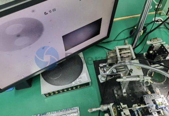
Chip-Scale Photonic Packaging: A New Era for Optical Fiber and Waveguide Alignment Systems
The emergence of chip-scale photonic packaging is a significant shift in optics. Manufacturers are concentrating on developing ultra-precise alignment systems to accommodate this miniaturization as the market for quicker, smaller, and more energy-efficient optical equipment expands. Here, the Optical Waveguide Alignment System and the Optical Fiber Alignment System are both being…
View On WordPress
0 notes
Text
Optical Fiber Alignment Systems Are Revolutionizing Next-Gen Communication Networks

Precision is crucial in the ever changing field of communication technology. The need for quicker, more dependable connections is only increasing, whether it is via 5G networks, high-speed internet, or data centres that fuel the cloud. The Optical Fiber Alignment System is a quiet but significant invention that is working behind the scenes.
An optical fibre alignment system: what is it?
A high-precision method for aligning optical fibres with nanometre accuracy is called an optical fibre alignment system. By ensuring that the cores of two fibres are precisely aligned, these systems reduce insertion loss and increase signal strength. Even the most sophisticated fibre networks will experience inefficient transmission in the absence of precise alignment.
Why is Alignment Important?
Networks are under more strain than ever before due to the exponential increase in data consumption—think video streaming, remote work, IoT, and AI. Accurately aligning optical components has a direct impact on:
Transmission Speed: Data transport may be slowed down by misalignment.
Signal Quality: Signal loss is decreased by precise alignment.
Network Reliability: Outages and error rates are increased by faulty connections.
Optical Waveguide Alignment System
The Optical Waveguide Alignment System goes beyond conventional alignment, which just considers fibres. It is intended to align integrated photonic waveguides as well as optical fibres, which are crucial parts of photonic chips that manage light-based data transfer on a micro scale.
These systems are necessary in:
Faster, smaller, and more energy-efficient circuits are made possible via silicon photonics.
In quantum computing, accuracy cannot be compromised.
Advanced Sensing: When photonic integration is needed in aeronautical or healthcare applications.
Optical Waveguide Alignment Systems are driving innovation in a variety of sectors by guaranteeing nearly flawless coupling between fibres and waveguides. The foundation of tomorrow's communication infrastructure is made up of Optical Fiber Alignment System and optical waveguide alignment systems, which may enhance the quality of your video conversations and enable cutting-edge technologies like photonic chips and quantum computing.
Next: PM Fiber Patch Cables: What They Are and Why They Matter
1 note
·
View note
Text
You Must Know This about Proper Crimping Techniques

For crimping, this is correct. To ensure a long-lasting connection, use proper crimping procedures throughout the fibre termination operation with a Fiber Crimping Machine. After all termination processes have been completed, the cable can be tugged without coming loose from the connection. Specify the maximum draw force for each fibre optic cable assembly industry specification, as well as any needs from your customer.
When correctly crimped, the cable assembly is strong enough to resist a decent amount of pulling throughout the final phases of manufacture and installation. Even after installation, the cable assembly may have to bear some mechanical stresses. A suitable fibre crimping machine ensures that force is applied to the connection rather than the delicate glass fibre.
Crimping, a modest but important step in the manufacturing process, often strengthens the cable assembly and protects the fibre. Proper crimping procedures assist in ensuring that the optical connection is maintained, which has a direct influence on dependability and performance over time. The Fiber Polishing Machine is also as useful as the crimping machine.
Best Crimping Techniques and Advice
The crimping procedure consists of the material to be clamped, the connector body, and a metal crimping sleeve, which is often made of aramid yarns, the cable's strongest element. To optimize your crimping methods, use these suggestions:
youtube
It is necessary to use the appropriate crimp tool. To get the optimum crimp and maximum draw force for that assembly, the connection manufacturer specifies the crimp tool for each connector body, die set, crimp sleeve, and crimp force. Using the appropriate tools and components is crucial. Crimped connectors are often textured and rough, which increases the contact surface area.
Using the incorrect crimp tool might result in a broken cable assembly; the crimp will most likely be too hard or too light. A crimp made with Fiber Crimping Machine with too much force might crush the connection. If this structure fails, the glass optical fibre may be destroyed as well. The aramid yarns might pull away if the crimp is too light, reducing the maximum pull power. You can utilize the connection manufacturer's suggested fibre curing oven or an automated crimp tool, which provides repeatability and improves process control by reducing operator fatigue.
2 notes
·
View notes
Text
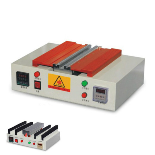
What is a Fiber Curing Oven and Why is it Important?
In fiber optic manufacturing and installation, achieving precise and durable connections is crucial. One of the most important steps in ensuring a reliable splice or termination is the curing process—this is where the fiber curing oven plays a vital role. A fiber curing oven is a specialized device used to cure (or harden) the epoxy or adhesive applied during the termination of fiber optic…
View On WordPress
1 note
·
View note
Text
Precision Stripping of Fibre Optic Cables: Why the Right Tools Matter
Yes, fibre optic light cables can be cut, which is a common procedure for fibre optic network construction, maintenance, or customization. However, cutting fibre optic cables demands accuracy and the proper instruments like Fiber Cable Cutting Machine to ensure the optical fibres’ integrity and signal quality. Steps to Cut Fibre Optic Cables Preparation: Begin by gently removing the cable’s…

View On WordPress
1 note
·
View note
Text
Optimizing Polarization Control: A Guide to Fiber Rotation Systems
Polarisation in optics refers to how the electric field of light is directed throughout its travel. Many optical devices, particularly in high-precision applications such as medical imaging, quantum computing, and telecommunications, require a certain polarisation state to function properly. Maintaining polarisation may be challenging, especially when light travels over long distances or passes through complex systems. The Polarization Maintaining Fiber Rotation System comes in handy in this case. The goal of these customised optical fibres is to eliminate polarisation state changes. However, even with PM fibres, active control and fine-tuning are usually necessary; here is where axis and fibre rotation systems shine.

Polarisation's Function Fibre Rotation System Maintenance
By allowing for controlled manipulation of the whole fibre, the Polarisation Maintaining Fibre Rotation System improves the axis rotation system. This method allows users to rotate the fibre while keeping the integrity of the polarisation state and modify the fibre's orientation.
Connect to Cutting-Edge Systems: works with other elements that maintain polarisation, such as couplers and modulators.
Encouragement Multidimensional Control: Allows for rotational changes to increase optical system accuracy and adaptability.
These systems are critical for field activities, manufacturing processes, and laboratories where precise control over polarisation is required.
Applications for Polarization Maintaining Fiber Rotation System and PM Axis Communications
Preserving polarisation integrity during high-speed data transfer reduces signal degradation and ensures efficient data flow. PM These methods are critical for fibre alignment in dense wavelength-division multiplexing (DWDM) systems.
Imaging in medicine
Polarisation control enhances image quality and resolution in imaging techniques like optical coherence tomography (OCT). PM rotations systems help alter polarisation states for the best imaging results.
Defence and Aerospace
Reliable optical systems are critical in harsh environments. For polarization-sensitive navigation, targeting, and communication applications, PM axis and fibre rotation systems provide the necessary stability.
Research & Development
These systems are critical in labs developing cutting-edge optical technologies, ranging from light-matter interactions to innovative photonic devices.
Choosing the Best System for Your Requirements
When selecting a fibre rotation system or Polarization Maintaining Axis Rotation System, consider the following factors:
Requirements for Precision: Choose a system with the accuracy needed for your use case.
Integration Capabilities: Check that it works with the optical components and systems you already have.
Environmental Conditions: If you work in a harsh or dynamic setting, you should utilise strong solutions.
Automation features: Determine if your process is better served by automated or human control.
1 note
·
View note
Text
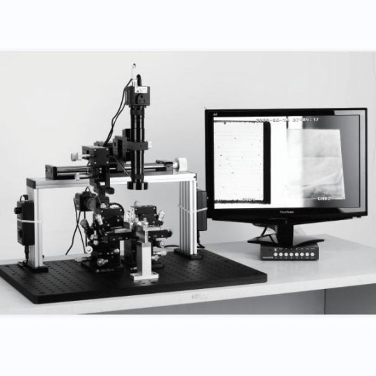
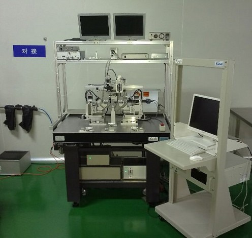
Optimizing Optical Networks: The Importance of Precise Optical Fiber Alignment Systems
For accurate and reliable data transfer in an optical network, a precise fibre alignment with Optical Fiber Alignment System is necessary. Many optical couplings are present in the majority of optical networks, and even small (1%) losses can cause significant signal loss and problems with data transport. In these networks, minimising coupling losses is essential. A properly aligned fibre produces the highest coupling efficiency and, thus, the least amount of signal loss before an optical system is assembled or packed. Power requirements are decreased by little signal loss, which leads to fewer repeaters, lower investment costs, and fewer failures.

Key Motion Parameters for Fibre Alignment
When employing motion control systems for fibre alignment, the motion parameters selected for each axis have a significant impact on the alignment process. The following are the major characteristics to consider when selecting a motion controller for the position of peak power in fibre alignment processes with Optical Waveguide Alignment System.
Minimum Incremental Motion (MIM) - The minimum amount of motion that a device can consistently and reliably provide. It should not be confused with resolution, which is calculated using the lowest controller display value or encoder increment. Rather, MIM refers to the controller's real physical performance, which allows for the change of the fibre location while looking for the position where maximal power is reached. The MIM of a motion controller might vary from 100 nm to 1 nm. While a smaller MIM can align the fibre closer to the maximum peak power, this capability comes at a substantial cost in terms of alignment speed and power increments.
The repeatability parameter refers to a motion control system's capacity to position itself repeatedly. It might be unidirectional or bidirectional.
Position stability is a measure of a motion system's ability to maintain a position within a specific window of time and error. Optical Fiber Alignment System for assembly processes like bonding is dependent on the fibres' positional stability once the peak power has been determined. Position stability requirements vary from 0.5 µm to a few microns.

Follow our Facebook and Twitter for more information about our product.
1 note
·
View note
Text
Connectivity Revolutionized with Fiber Taper Machines
The importance of robust and efficient fibre optic connections in the ever-changing world of data transmission and telecommunications cannot be overstated. Because fibre optic technology provides more capacity, lower latency, and faster data transfer, it has become the backbone of modern communication networks. The FBT Fiber Taper Machine is an essential component at the heart of this…

View On WordPress
1 note
·
View note
Text
Fiber Polishing Film: Essential Tool for High-Quality Fiber Optic Connections
In the world of fiber optics, achieving low-loss, high-performance connections is crucial for ensuring fast and reliable data transmission. One of the key tools used to accomplish this is Fiber Polishing Film — a specialized abrasive material designed for precisely polishing the end faces of fiber optic connectors. Proper polishing ensures optimal light transmission and minimizes connection…

View On WordPress
0 notes
Text
Fiber Optic Cable Manufacturing Process
A Fibre Cable Cutting Machine is intended to cut cables of various diameters and wound them into the appropriate length and annular shape, with the benefits of accurate measurement, a series of cutting and winding, and simple automatic operation. It may adjust lengths, speeds, and numbers to increase manufacturing efficiency. This page will give some basic information on fibre optic cable-cutting machines.

What is a Fibre Optic Cable Cutting Machine?
A fibre optic cable cutting machine is a professional tool used in fibre optic patch cord/pigtail production lines to measure cable length, cut, count, wind, roll, and spray word marking (optional).
Features & Benefits
The qualities and benefits of a fibre optic cable-cutting machine are as follows:
Cut up to 500m of cable length.
Optional cable arrangement feature.
Touch screen for convenient operation.
High manufacturing efficiency.
Applications
Fibre optic cable cutting machines are used in fibre optic patchcord/pigtail production lines, FTTH, and other applications.
To begin manufacture of any form of patch cord, the cable must be cut to the proper size. This appears to be a straightforward operation, but it takes some caution.
We must be aware of various issues that may arise throughout the fibre cutting procedure if we are not diligent.
Avoid excessive bending. Throughout the cutting operation, we must preserve the bending radius within the cable's specifications. However, we must constantly examine the manufacturer's recommendations.
Never use greater pulling force than advised. Typically, the cable is cut from a spool containing 2 or 4 kilometres of cable. Even while utilising equipment that allows us to easily rotate the reel to retrieve the cable, we must avoid pulling on the outer insulation or jacket. The Fiber Polishing Machine is also practical.
The power element beneath the jacket is aramid yarn, often known as Kevlar. Under that are the primary and secondary buffers, as well as the fibre optic.
If we draw the coil cable through the jacket, it will pass through the aramid yard, which is the strength factor. Stretching is inevitable due to its lack of flexibility. Later, this soft plastic will tend to return to its original place, revealing the Kevlar.
To prevent this, the fibre cutting equipment must unwind the cable automatically when the counting machine pulls.
Still, there must be a system in place to mitigate the impact of the cut's commencement. This mechanism consists of two pulleys: one stationary and one movable. The cable travels through them multiple times, resulting in a cable buffer. This buffer will be used from the moment the unwinder is turned on and will keep up with the cable requirements.
Conclusion
The Fibre Cable Cutting Machine features excellent production efficiency and precision, as well as length and speed settings that are adjustable, automated, and simple to use.
youtube
Follow our Facebook and Twitter for more information about our product.
1 note
·
View note
Text
Optical Fiber Alignment
Precise Optical Fiber Alignment System is required for precise and dependable data transmission in an optical network. Most optical networks contain several optical couplings, and even slight losses at these couplings can result in substantial signal loss and data transfer issues. Minimising coupling losses is crucial in these networks. Prior to assembly or packing of an optical system, good fibre alignment results in the best coupling efficiency and hence the least amount of signal loss. Minimal signal loss reduces power needs, resulting in fewer repeaters, cheaper investment costs, and fewer failures.
A well-characterized input beam is linked into the fibre under test, and a raster scan of the fibre is performed to identify first light, which is the output signal from the fibre that indicates when the laser beam first enters the fibre. Once the initial light is detected, the location of the fibre is modified in a lateral, longitudinal, and angular coordinate system to determine the peak intensity of the output optical signal. A successful fibre alignment solution necessitates the modification of various critical motion parameters utilising a precision motion control device and a search method appropriate for the application.
Key Motion Parameters For Fibre Alignment
When employing motion control systems for Optical Waveguide Alignment System, the motion parameters selected for each axis have a significant impact on the alignment process. The following are the major characteristics to consider when selecting a motion controller for the position of peak power in fibre alignment processes.
Minimum Incremental Motion - The least amount of motion that a gadget can consistently and dependably produce. It should not be confused with resolution, which is calculated using the lowest controller display value or encoder increment. Rather, MIM refers to the controller's real physical performance, which allows for the change of the fibre location while looking for the position where maximal power is reached. While a smaller MIM can align the fibre closer to the maximum peak power, this capability comes at a substantial cost in terms of alignment speed and power increments.
The repeatability parameter describes a motion control system's capacity to achieve a repeatable position. It might be unidirectional or bidirectional. Fibre alignment systems generally have a bidirectional repeatability of 1 µm to a few nm. This characteristic is useful for rapidly determining the peak power location of similar device designs.
Optical Fiber Alignment System is a measure of a motion system's ability to maintain a position within a specific window of time and error. Aligning fibres for assembly processes like bonding is dependent on the fibres' positional stability once the peak power has been determined. Position stability requirements vary from 0.5 µm to a few microns.
1 note
·
View note
Text
Crimping Tool Types and Operation
Fiber Crimping Machine are used to combine two pieces of metal or other malleable materials. Crimping requires a strong joint to guarantee that the application functions effectively. Crimping tools are offered in a variety of styles to accommodate a wide range of applications. The structured cabling system emphasises following the techniques that will provide elegance, discipline, method, and…

View On WordPress
0 notes
Text
Enhancing Efficiency with a Fiber Cable Stripping Machine
In the world of fiber optic technology, precision and efficiency are crucial. A fiber cable stripping machine is one of the most essential tools for fiber optic installation and maintenance. This advanced equipment is designed to remove the protective coating from fiber optic cables with precision, ensuring the integrity of the delicate optical fibers inside. Why Use a Fiber Cable Stripping…

View On WordPress
0 notes
Text
You Must Know These about Proper Polishing Techniques
For crimping, this is correct. To ensure a long-lasting connection, use proper crimping procedures and a Fiber Crimping Machine throughout the fiber termination operation. After all termination processes have been completed, the cable can be tugged without coming loose from the connection. Specify the maximum draw force for each fiber optic cable assembly industry specification, as well as any needs from your customer.

When correctly crimped, the cable assembly is strong enough to resist a decent amount of pulling throughout the final phases of manufacture and installation. Even after installation, the cable assembly may have to tolerate some mechanical stresses. A suitable fiber crimping machine ensures that force is applied to the connection rather than the delicate glass fiber.
Crimping, a small but important step in the manufacturing process, typically strengthens the cable assembly and protects the fiber. Proper crimping procedures and Fiber Polishing Machine assist in ensuring that the optical connection is maintained, which has a direct influence on dependability and performance over time.
Advice on Best-Practice Crimping Techniques
The crimping procedure consists of the material to be clamped, the connector body, and a metal crimping sleeve, which is often made of aramid yarns, the cable's strongest element. To optimize your crimping methods, use these suggestions:
To get the optimum crimp and maximum draw force for that assembly, the connection manufacturer specifies the crimp tool for each connector body, die set, crimp sleeve, and crimp force. Using the appropriate tools and components is crucial. Crimped connectors are often textured and rough, which increases the contact surface area. In the overall assembly, such features contribute to the greatest draw force.

Using the incorrect Fiber Crimping Machine might result in a broken cable assembly; the crimp will most likely be too hard or too light. A crimp with too much force might crush the connection. If this structure fails, the glass optical fiber may be destroyed as well. The aramid yarns might pull away if the crimp is too light, reducing the maximum pull power. As a side note, you can utilize the connection manufacturer's suggested fiber curing oven or an automated crimp tool, which provides repeatability and improves process control by reducing operator fatigue.
Main Source: https://sunmafiber.medium.com/
0 notes