
Don't wanna be here? Send us removal request.
Statistics
We looked inside some of the posts by sychronous and here's what we found interesting.
Average Info
Notes Per Post
1
Likes Per Post
1
Reblog Per Post
0
Reply Per Post
0
Time Between Posts
3 days
Number of Posts By Type
Text
5
Last Seen Tumblr Blogs


Fun Fact
Tumblr was the first site to host the blog for President Barack Obama in 2011.
Text
Hybrid stepper motors
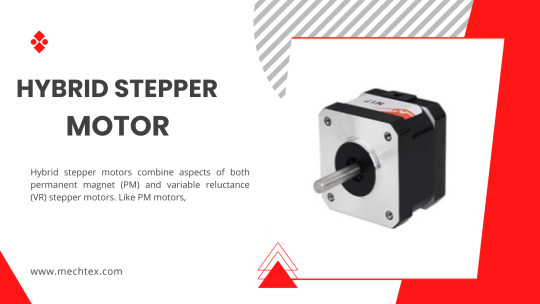
Hybridstepper motors combine aspects of both permanent magnet (PM) and variable reluctance (VR) stepper motors. Like PM motors, they contain a permanent magnet in the rotor teeth. Two sets of teeth called cups ring the rotor. One ring is all south poles, and the other ring is all north poles.
Like VR motors, hybrid stepper motors have stator poles. Note that stator poles in hybrid motors are sometimes called teeth. (For more information, read FAQ: What is pole count and why does it matter?) More after the jump.
How here are the rotor and stator of a hybrid stepper motor. Two soft iron cups sport teeth to guide the flux from a permanent magnet to the rotor-stator air gap.
To illustrate how these motors work, consider a 1.8° hybrid stepper. The teeth of one ring are offset from those on the other ring by 3.6°. The stator poles are offset by 90° and these are opposite polarity, so that every 180° the stator poles are in identical polarity. The rotor poles exist in sets of four, with two being north poles and two being south poles. The rotor poles align alternately with the rotor’s teeth and cups, so that one set of rotor poles attracts fully while the other attracts and repels ¾, ½ or ¼ of a tooth. If there are 50 teeth, the pitch angle is 7.2° … so at the next step, the motor rotates to the next closest step, which is 7.2° × ¼ = 1.8°.
When the current changes, the rotor can turn a very small amount—an improvement over basic PM motors and VR motors. Newer control techniques such as half-stepping and microstepping let designers get even finer movements of rotation, which make for more exact output than that from VR stepper motors (which can’t usually be microstepped). Hybrid stepper motors also have higher torque-to-size ratios and higher output speeds than other stepper-motor types. They are also quieter than VR stepper motors.
One caveat is that hybrid stepper motors are more expensive than other step motors. So, designers should weigh the higher cost against the advantages of quiet operation, smaller steps, and torque output before making a final step-motor selection.
0 notes
Text
Reduction Gearheads
Reduction gearheads use the concept of gear reduction which implies that the gears reduce the speed of the machine but increase its torque. They are usually made of steel, hardened metal, nylon, plastic or rubber gear. The usage of sintered gears is also increasing to decrease the expense of gear production. These are self lubricating. They are available with a variety of mounting options, reduction ratios and output shafts.
Types of Reduction Gearheads
Single Reduction Gearhead
The single reduction gearhead consists of one pair of gears. It consists of ports via which the engine and propeller shafts enter the arrangement. A small-sized gear, called the pinion, directly runs a gear that is connected to the propeller shaft.
Double Reduction Gearhead
The double reduction gearhead is mostly used in applications where very high speeds are required. In this arrangement, a small gear, called pinion, is anchored on the input shaft allowing a flexible coupling. The pinion is attached to an intermediate part known as the first reduction gear.
Magnetic Reduction Gearhead
The magnetic reduction gearheads, also called magnetic gear reducers, can beneficially replace the conventional gear reducers to provide torque and speed control. This arrangement works on the principle of magnetic attraction instead of physical contact between the shifting components. Complicated assembly, lower torque and heavy weight have slowed the diffusion of the magnetic process.
The magnetic reduction gearheads eliminate the need to lubricate and hence have a low maintenance cost. Since there is no requirement for lubrication, the machines can run in an extreme temperature range of -200? C to 350º C. It is used in applications such as satellites and other aerospace instruments.
Since there is no physical contact between moving parts in this arrangement, there is an absence of friction. This not only eliminates wear but also has an appreciable effect on the life of the machine.
Parallel Shaft Reduction Gearhead
The parallel shaft reduction gearhead consists of a multiple gear assembly. This arrangement enhances the system reduction. The entire gear reduction ratio is defined by enhancing each gear ratio from every gear part.
If the pinion and its anchoring part have the same number of teeth, then reduction does not take place. In this case, the gear ratio is 1:1. The gear is used as an idler whose main function is to change the rotation direction and not decrease or increase the speed or torque, respectively.
Following components are used in the parallel shaft reduction gearhead :
i) Top and bottom plates that are provided with dust cover or a casting with a top plate
ii) Various types of gears including metal, plastic, PU, sintered, nylon, delrin, hardened metal and brass.
Planetary Reduction Gearhead
The gear ratio in the planetary reduction gearhead depends on the number of teeth of the ring gears and the sun ring gears. The planet gears function as idlers and do not affect the gear ratio. The planetary gear ratio is the summation of the number of teeth on the ring and sun ring gears divided by the number of teeth on the sun ring gear.
Right-angle Worm Reduction Gearhead
The right-angle worm reduction gearhead depends on the count of teeth on the mating worm wheel and the count of threads or starts on the worm.
Reduction Logic
Ratio Calculation
The gear ratio, also known as the reduction, is obtained by dividing the number of teeth on the larger gear by the number of teeth on the smaller gear.
Torque Calculation
Mo = Mi r ?
where,
Mo = output torque (Nm)
Mi = input torque (Nm)
r = gear transmission ratio
? = gear efficiency (%)
Power calculation
Po = Pi ?
where,
Po = output power (W)
Pi = input power (W)
? = gear efficiency (%)
Factors To Consider While Selecting Reduction Gearheads
Direction of Rotation
The direction of rotation indicates the direction of the output shaft relative to the motor.
Efficiency
The efficiency is mostly dependent on the number of trains. It is a mean value that is measured at a surrounding temperature of 20º C to 25º C. A newly bought gearbox will show lower values. These values will however reach the normal values post the run-in period.
Maximum Static Torque
The peak torque offered at stall is referred to as maximum static torque. The value of torque beyond this limit may destroy the gearbox.
Maximum Recommended Input Speed
The maximum recommended input speed has a great impact on the noise level and the lifetime of the gearhead. Depending on the application, it should be taken into consideration while deciding the reduction ratio.
Backlash
Backlash is the angle that a gearhead output shaft can rotate freely with a blocked input. It occurs mostly due to gear play which is necessary to avoid jamming. It can also occur due to shaft play and elastic deformation of the teeth and shafts under load.
Advantages
Higher torque output
Speed reduction
Higher resolution
Can drive large inertial loads
Shorter positioning time
Downsize
Improved damping characteristics
Increased axial and radial load
Increased rigidity
Longer life
Less maintenance required
Disadvantages
The gear operation is noisy.
They are not favourable for greater velocities.
They are not favourable for transmitting motion over a large distance.
No flexibility.
May get permanently damaged on excessive loading.
Applications
Lifter
Construction
Tank fabrication
Security Camera
Mining industry
Conveyors
Crushers
Cooling towers
Agitators
Elevators
Extruders
Filters
0 notes
Text
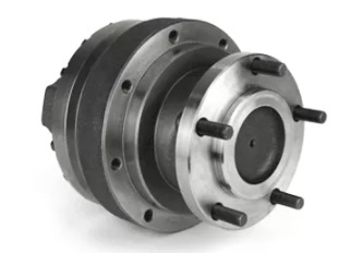
Planetary Gear
Planetary Gear
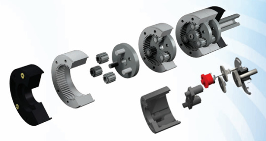
A planetary gearhead is a device in which the output and the input shafts are aligned. The primary function of the planetary gearhead is to offer the greatest torque in the most compact manner. They offer a greater torque and a higher reduction ratio per gear train. They are made of good quality composite materials.
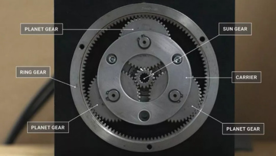
Why the name ‘Planetary’ ?
The planetary gearbox gets its name from its resemblance to our planetary system. Just like our solar system, it consists of a ring gear (satellite), a solar gear (sun) and two or more planet gears (planets) set together. The solar gear is usually moving and also puts the planet gears in motion which are bolted in the planet carrier. These make the output shaft. The ring gears are stationary and have a fixed location with respect to the surrounding components. This complete assembly resembles the solar system, also known as the planetary system and hence the name planetary.
Construction of Planetary Gearhead
A basic planetary gearhead consists of four basic components:
Sun gear : The central gear that runs the surrounding planetary gears
Ring gear : The outermost gear
Planet gears : There are multiple planet gears between the sun and the ring gears.
Carrier : It is the assembly that holds the planet gears together. It also keeps the planet gears equally spaced in an orbit.
These three components make one stage of a planetary gearhead. One can devise double or triple stages for greater ratios. Also, the torque density can be increased by using a greater number of planet gears between the sun gear and the ring gear. Planetary gears can be excited with the help of a motor.
Principle of Operation
The planetary gearboxes are used to energise anything, be it a simple plant device or some cutting edge electrical system. These are basically used in applications that require higher torque density, good functional efficiency and higher durability.
In a planetary gearhead, multiple teeth run simultaneously. Due to multiple teeth running simultaneously, the machine offers a high-speed reduction with a comparatively smaller gear. Also, a lower inertia is reflected back to the system.
The collective sharing of the load by numerous teeth allows the planetary parts to give out higher levels of torque.
Consider, the sun gear has s teeth, planetary gears have p teeth and the stationary annulus has a teeth, then
Reduction ratio per train = (a:s) + 1
Types of Planetary Gears
Depending on their performance, one can classify planetary gears into three types :
Wheel Drive Planetary Gear

The sun gear moves the surrounding planetary gears. In the wheel drive planetary gear, these planetary parts are connected to a carrier. When the sun gear is run, the planetary gears circulate the ring gear which is on the outer side.
The wheels can be put together over the housing of the system. This type has the advantage of optimizing the size of the system by connecting the wheel directly to the gearbox.
Shaft Output Planetary Gear

As in wheel drive planetary gear, the sun gear runs the surrounding planetary gears. In shaft output planetary gear, these planetary parts are housed in a turning carrier. The ring gear is stationary with the turning carrier providing drive to the shaft. The housing part of the system is connected directly to the machine with the output being a turning shaft.
The output shaft consists of gears of different sizes. The gears are in a constant mesh with the countershaft gear. The gears rotate freely from the output shaft but once engaged they are stuck to the output shaft. The output shaft rotates according to the power transferred by the gears.
Spindle Output Planetary Gear
Spindle output planetary gear functions in a similar fashion to the shaft output planetary gears. However, unlike shaft output planetary gearheads, the output is provided as a flange.
Reduction Logic
Ratio Calculation
The gear ratio, also known as the reduction, is obtained by dividing the number of teeth on the larger gear by the number of teeth on the smaller gear.
Torque Calculation
Mo = Mi r μ
where,
Mo = output torque (Nm)
Mi = input torque (Nm)
r = gear transmission ratio
μ = gear efficiency (%)
Power calculation
Po = Pi μ
where,
Po = output power (W)
Pi = input power (W)
μ = gear efficiency (%)
Characteristics of Planetary Gearheads
Higher reduction ratio per train.
Higher torques can be obtained
Both input and output of a train have the same direction of rotation
Lesser backlash
Advantages
Requires lesser trains for a specific reduction ratio
Offers higher gear ratio in compact space
For a similar gear ratio, the planetary gearhead will be lighter in weight compared to the traditional gearheads.
Offers greater efficiencies of about 0.92 per stage.
It has a higher torque transmission capability.
It will have lower inertia.
This arrangement offers higher stability.
It has a good service life.
In this arrangement, the driving and driven members are concentric. Hence, the driving and driven equipments can be installed in the same line line. This allows space saving.
Compact design of gearbox.
The load will always rotate in the same direction as the motor, for any number of trains.
Smaller shock on paid reversal of motor rotation.
Disadvantages
Higher cost compared to the traditional gears.
Complex designing and manufacturing
It is difficult to determine the efficiency of planetary gears.
Gearing needs to be accurate.
Some planetary gear arrangements make additional noise during operation.
The driving and driven members of the planetary gear system must be concentric to avoid any additional gearing.
Applications
Owing to the numerous advantages, planetary gears have various applications. Following are a few applications of the planetary gears :
Robot, to improve the torque
Printing press, to reduce the speed of rollers
Precise positioning
Packaging machine for reproducible products
Wheel drives
Track drives
Conveyors
Slew drives
Hoist drives
Mixing
Winch drives
Pumps
Coil tubing injectors
Auger and drilling drives
Cutter head drives
Harbour mobile cranes
EOT cranes
Automation assembly
Printing Lathe
Clock
Toys
Turbine engine
0 notes
Text
Stepper Motor
Introduction
Pro-Lite supplies a wide range of precision opto-mechanical and motion control equipment. Motorised positioning systems are deployed to conveniently and precisely automate complex motion sequences. Various motor technologies are available, including conventional DC motors, stepper motors as well piezoelectric motors. This article reviews the theory and attributes of stepper motors.
What is a Stepper Motor?

Permanent magnet (PM) stepper motors use a PM in the rotor and operate on the attraction or repulsion between the rotor PM and the stator electromagnets.
Variable reluctance (VR) stepper motors use a plain ferromagnetic rotor and operate based on the principle of minimum magnetic reluctance. The minimum magnetic reluctance occurs when the gap between the energised stator electromagnet and rotor teeth is at its minimum i.e. the rotor will move to be aligned with the magnetic field which can be used to generate rotation.
Hybrid stepper motors operate using a combination of PM and VR stepper motor methods.
Basic Stepper Motor Operation
By using a sequence of electrical pulses, the stator electromagnets can be energised in such a way as to induce rotational motion in the rotor. A simplified permanent magnet 2-phase stepper motor is illustrated below (see Figure 2).
With reference to Figure 2:
Phase A is energised which causes the rotor to move into alignment with the energised stator coils.
Phase A is switched off and phase B is energised on adjacent coils, this causes the rotor to rotate 90° clockwise.
Phase B is switched off and phase A is re-energised but this time with a reversed polarity (A-), this causes a further 90° clockwise rotation of the rotor.
Phase A- is switch off and phase B is re-energised but this time with a reversed polarity (B-), this causes a further 90° clockwise rotation of the rotor.
Repeating this sequence causes the rotor to continue rotating. For counter clockwise rotation the sequence should be reversed. Each step moves the rotor through a fixed angle, the angle depending on the number of rotor teeth within the motor. A typical full step angle found in a 2-phase stepper motor is 1.8° per step, which means that one full rotation of the rotor will take 200 full steps.
Microstepping for Smoother Motion and Increased Precision
By varying the amount of current applied to the stator coils it is possible to increase the step resolution of the motor to be finer than the full step angle. This is achieved by delivering two sine wave current signals 90° out of phase to adjacent stator coils. This has the effect of decreasing the current in one coil as it is increased in the adjacent coil, this will cause the rotor position to lie somewhere between the two coils (see Figures 3 & 4). This is known as a microstep and the size of the smallest microstep achievable is dependent on the resolution of the driving electronics used to energise the stator coils.
As an example, the LIMES 84N stepper motor linear stage from OWIS uses a stepper motor with 200 full steps per revolution (see Figure 5 for a 3-axis assembly). When used with the OWIS PS 90 position control unit it is possible to divide each full step into a further 256 microsteps. This gives a total of 51,200 microsteps per revolution of the motor or 0.007° per microstep. When converted into linear motion via a precision ball screw, microstepping allows very fine position increments to be made.
In addition to improving the precision of the motor there are a number of performance advantages created by microstepping. One key advantage is the reduction of torque ripple, which is often encountered when operating in full step mode. In full step mode the stator coils are either energised with maximum current or switched off, which means that as the rotor moves between each full step position there is a large variation in the available torque. Torque ripple results in rough, unstable motion which leads to noise and unwanted vibrations. Microstepping solves this issue as the stator coil current is applied more gradually, resulting in a smoother transition between steps.
Open Loop Operation for Simplified Control
Each microstep of a stepper motor corresponds to a small fixed motion increment. In order to reach a certain position, the controller need only count the number of microsteps travelled from a home or reference position. No additional position feedback encoder is required in open loop mode. This results in a more straightforward and less costly motion control solution. Open loop mode also allows the motor to have an excellent response to input drive signals, producing quick start / stop response times. Due to the absence of feedback and servo control in open loop operation, a stepper motor can hold a fixed position with a very high degree of stability without any unwanted servo dither. Similarly, as the stator coils remain energised even when stationary, a high holding torque can be achieved, making stepper motors ideal for step and hold applications.
Stepper Motor Disadvantages
There are some drawbacks to stepper motors. Primarily the lack of position feedback can lead to situations where the position integrity may be compromised, particularly if used under heavy loads that exceed the torque specification of the motor. High loads can cause unwanted movement or stalling of the motor, which combined with the lack of position feedback, can result in an incorrect position readout.
The open loop mode also requires that a position reference be taken if the absolute position is required. This means that homing cycles need to be executed before an application can run. Position information will also be lost if the motor or controller suffers a power failure requiring a fresh homing cycle before the application can resume. If absolute position is critical to an application, then using a motion control solution with absolute position feedback would be more suitable.
Whilst one of the advantages of stepper motors is their ability to hold a fixed position, this mode of operation can also have a downside. The stator coils remain energised when stationary or when operating at low speeds, which means that excess heat is generated. Without effective heat removal this excess heat can become a problem for sensitive applications. This can be overcome by carefully controlling the phase currents supplied to the motor but at the expense of holding torque. In these situations, it may be better to consider a DC servo motor as an alternative.
At low speeds and at low rates of acceleration, stepper motors are often the preferred choice. However, at higher rotational speeds the torque that can be generated by a stepper motor reduces. The drive signals sent to the stator coils generate a magnetic field within the coils. it is this magnetic field that induces a motion in the rotor. When operating at low speeds there is enough time for the current flowing through the coil to induce a strong magnetic field, allowing the motor to provide its fully rated torque performance. If the speed of rotation is increased there is less time for the coils to fully energise in response to a drive signal. This results in a reduced amount of torque available to the motor. For applications which require high speed with high torque then a servo motor would be able to offer improved performance over a stepper motor.
Summary
Stepper motors offer a very effective motion control solution, often at lower cost than an equivalent servo motor. They are also highly reliable, containing no contact bushes within the motor, improving the motor lifetime, and making them an ideal solution for OEM and industrial applications.
The ability of a stepper motor to operate in microstep mode can provide a very high degree of precision that is frequently required in many photonics motion control applications. The microstepping ability also gives a stepper motor a wide velocity range and can provide stable motion even at very low velocities.
The simplified open loop operation of stepper motors is also a major advantage, providing cost and time saving benefits to the end user. A large number of sizes and power options are readily available, which allows stepper motors to be used in a wide range of precision motion control applications, including:
Image scanning
Step and hold positioning and measurement
Camera and sensor positioning
Lens and mirror positioning
2D and 3D printing applications
Applications that require low acceleration and a high holding torque
0 notes