#Crankshaft Repair Services
Text
Service Providing For Crankshaft Grinding Repair
With regard to the more traditional onsite crankshaft grinding equipment utilized by businesses, we have the most recent design of onsite crankshaft grinding equipment. By using the crankshaft grinding method to repair the crankshaft, we are able to keep the crankpin and main journal's taper and ovality strictly within the manufacturer's specifications and tolerances specified in the handbook. More than 10,000 crankshaft grinding and crankshaft repair services have been completed successfully by our company. For more information on crankshaft polishing, marine crankshaft repair, and crankshaft grinding repair services email [email protected] or call +91 9582647131, tel. 124-425-1615.
#Crankshaft Repair#Crankshaft Grinding Services#crankshaft grinding repair#Crankshaft repair#grinding of crankshaft#metal stitching#crankshaft grinding machine#crankshaft polishing on vessel#Crankshaft Repair Services#onsite crankshaft grinding#crankshaft repair and crankshaft grinding#diesel engine crankshaft#Crankshaft grinding#onsite crankshaft grinding machine#Onsite repair of crankshaft
2 notes
·
View notes
Text
Revitalize your engine's performance with RA Power Solutions! Our expert crankshaft repair services will breathe new life into your machinery. Don't let a damaged crankshaft slow you down – check our website now for precision repairs and unbeatable quality! For more information, call us at +91 9582647131.
0 notes
Text
Onsite Crankshaft Grinding Repairing Service
The onsite crankshaft repair services of the crankshaft help in get the engine back into operation in the shortest possible time. Onsite crankshaft repair services involve the repair and maintenance of crankshafts without the need for disassembly and transportation to a workshop. This approach saves time, money, and resources, making it an attractive choice for various industries such as marine, power generation, and locomotives. RA Power Solutions specializes in providing comprehensive onsite repair solutions, and onsite repair services of crankshaft ensuring for minimal disruption to operations. For any services related to crankshaft grinding, crankshaft repair, crankpin polishing, or onsite crankshaft repair services, contact us by email at [email protected], 0124-425-1615, or +91-9810012383.
#onsite crankshaft repair#crankshaft repair services#crankshaft repair#crankshaft grinding and repair#onsite crankshaft polishing
0 notes
Text
https://www.marineengine.in/blog/2019/06/12/hand-polishing-of-crankshaft-journals-consequences-of-hand-polishing-crankshaft-grinding-equipment-ra-power-solutions/
Made Polishing of the Crankpin and Main Journal Simple
RA Power Solutions while working on the marine engines' crankshafts In order to get engines back in working order, unconventional methods for crankshaft polishing and polishing the main journal and the crank pin journal are used, as has been noticed over the years. The crankshaft repair procedure has been simplified by RA Power Solutions with the least amount of engine downtime possible thanks to the introduction of lightweight, compact onsite crankshaft polishing equipment. To know more about Babbitt white metal, used connecting rod repair, and crankshaft straightening, contact us at [email protected], 0124-425-1615, or +91-9810012383.
#Polishing of Crankpin#crankshaft repair#crankshaft repair services#crankshaft grinding and repair#crankshaft grinding#onsite grinding and polishing#crankshaft polishing on vessel
0 notes
Text
In case of any emergency failure or breakdown to the crankshaft, crankpin and main journal, we can inspect it and execute crankshaft repair services within a minimum time. The main advantage of onsite crankshaft grinding and repair services to the damaged shaft or crankpin journal is that it requires very less time to repair and it also works out to be cheaper. In this process of onsite repair, there is no need of removing the shaft from the entablature. For any information regarding our services, please contact us at [email protected], 0124-4251615, or +91-9810012383.
#crankshaft repair#crankshaft grinding#crankshaft polishing#crankshaft polishing machine manufacturers#crankshaft polishing machine#crankshaft grinders#insitu crankshaft grinding repair#crankshaft repair services#crankshaft polishing tool#caterpillar crankshaft repair
0 notes
Link
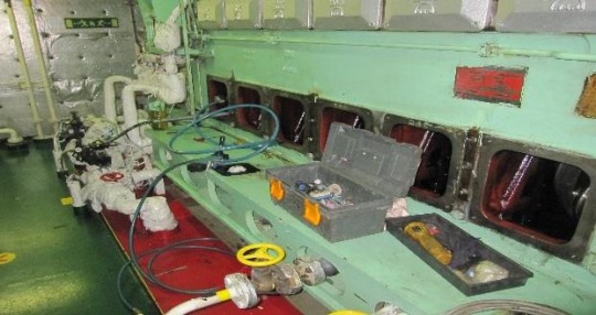
RA Power was engaged by Miami US based reputed shipping company to inspect and repair the crankshaft of the Wartsila engine. Due to a Wartsila 12V32 crankshaft failure, the vessel was outside of Anchorage. Contact us at [email protected], [email protected], and +91-9582647131 Tel. +91-124–4378292 available for more information.
#Wartsila Crankshaft Repair#Wartsila Crankshaft Grinding#crankshaft grinding#crankshaft in situ machining and polishing#insitu crankshaft machining#insitu crankshaft#machining and polishing#polishing#Wartsila crankshaft#in situ machining of Wartsila crankshaft#crankshaft repair services#crankshaft repair#crankshaft repair services for Wartsila#wartsila engine#onsite crankshaft grinding#onsite crankshaft grinding machine#crank pin grinding machine#Wartsila#repair services#in situ machining#Wartsila engine crankshaft
0 notes
Text

Manufacturers And Suppliers Of Crankshaft Grinding Machine: RA Power
With over 44 years of experience in crankshaft maintenance, RA Power Solutions manufactures and supplies crankshaft grinding machines worldwide. The crankshaft grinding machine is well-liked by big shipping firms, diesel power plants, the heavy engineering sector, etc. because of its extremely low cost. Contact us at [email protected] or [email protected], or give us a call at +91 9582647131, 9810012383, with any questions you may have about on site portable crankshaft grinders or crankshaft grinding machine suppliers.
#In Situ Crankshaft Grinding Machine#Manufacturers of crankshaft grinding machine#Onsite crankshaft repair#Services of crankshaft grinding polishing
0 notes
Text
On Site Crankshaft Grinding Machine | Global Onsite Repairs
Experience precision and convenience with our On Site Crankshaft Grinding Machine. Elevate your machinery's performance worldwide with Global Onsite Repairs. Trust us to restore your engines to perfection. Act now for seamless on-site solutions! Your equipment deserves the best. Get more information regarding the Machining of Crankshaft, and metal stitching cast iron by contacting us at [email protected], 0124-425-1615, or +91-9810012383.
#onsite crankshaft grinding#crankshaft grinding machine#on site crankshaft grinding machine#crankshaft repair#crankshaft polishing services
0 notes
Text
Five Signs Your Timing Belt Tensioner is Faulty

In most cars, the timing belt is a crucial component of the internal combustion engine (some have a timing chain). This is in charge of making sure the camshaft and crankshaft are spinning simultaneously.
In this manner, the engine's valves will operate according to schedule. The intake and exhaust strokes of the engine's cylinders should coincide with how the valves operate.
The strong rubber and nylon-reinforced cords that make up a timing belt are its two major components. Numerous pulleys and gears are constantly in touch with the belt.
The belt eventually becomes too loose as a result of wear and tear. Because of this, a timing belt tensioner is employed to keep the belt in place.
It will essentially be like having a faulty timing belt if the timing belt tensioner malfunctions because it won't be able to perform its intended job. Your engine will have a variety of issues as a result, including poor performance.
You should be sure to replace your timing belts and chains along with any tensioners according to the manufacturer's schedule for doing so. In order to schedule your timing belt kit replacement before it becomes too loose or breaks, you can search online for vehicle service near me garages. If the timing belt/chain does snap, in such case, a complete engine replacement is what you'll probably be looking to do.
Here are five of the most typical indications that your timing belt tensioner needs to be replaced. It may be time to change your tensioner if you observe more than one of these:
1.Check Engine Light - The timing of the valves will be off if the timing belt is loose as a result of a defective tensioner, which would trigger the check engine light. The check engine light will then turn on the dashboard, indicating that there are issues with the engine. Since the check engine light by itself can indicate a myriad of problems, you could use a car diagnostic tool to scan for any fault codes and validate the problem. Have the engine management light issue identified and required repairs made before scheduling your next MOT testing service to avoid a failure.
2.Knocking Sounds - The timing belt will start to knock around and hit the timing cover and other components inside the timing cover when it becomes loose. If the sound does not exactly resemble knocking, it can sound more like slapping. If you start to hear this sound, search online for car services near me garages and book your car in as soon as you can with a competent mechanic fully diagnose and repair the issue.
3.Engine Not Turning Over - The camshaft and crankshaft are not synchronised due to a loose timing belt caused by a broken tensioner. You won't be able to ignite the combustion of the fuel and air in the chamber as a result. The vehicle won't start when you turn the key in the ignition, yet the engine might begin to sound.
4.Grinding Noises - The pulleys themselves will generate grinding or rattling noises if the timing belt doesn't have a tight grasp on them. This will undoubtedly occur if the pulley bearing fails.
5.Engine misfires - An engine misfire is caused when the cylinder's valves open or close too quickly. If the timing belt is unable to move both the crankshaft and camshaft simultaneously, this will occur. Check your car's MOT status and repair this problem before your next MOT test to prevent failing the emissions test.
A Timing Belt Tensioner's Lifespan
The manufacturer may not have specified a suggested change interval for the tensioner, unlike the timing belt itself. The timing belt should typically be replaced between 75,000 and 100,000 miles, and in almost all cases, the timing belt tensioner should be replaced at the same time.
While the tensioner's lifespan is really considerably greater than the timing belt's, you'll save a lot of money in the long run if you replace it together with the water pump when you change the timing belt. This is because the tensioner is frequently fairly difficult to access.
#mot history#check mot#check mot history#mot history check#check mot status#mot status#check my mot history#mot history checker#mot testing service
1 note
·
View note
Text
John-Deere 3029, 4039, 4045, 6059, 6068 Engines (Saran)-499999CD Disassembly
This article describes the disassembly of John-Deere 3029, 4039, 4045, 6059, 6068 Engines (Saran)-499999CD
John Deere Service Advisor Electronic Data Link EDL2 Diagnostic Adapter High Quality

ENGINE DISASSEMBLY SEQUENCE
The following sequence is suggested when complete
disassembly for overhaul is required. Refer to the
appropriate repair group when removing individual
engine components.
1. Drain all coolant and engine oil. Check engine oilfor metal contaminates (see Groups 25 and 30).
2. Remove fan belts, fan, and alternator (seeGroup 30).
3. Remove turbocharger (if equipped) and exhaust manifold (see Group 35).
4. Remove rocker arm cover with vent tube. On engines having an Option Code label on rocker arm cover, be careful not to damage label (see Group 05).
5. Remove water manifold with thermostats (see Group 30).
6. Remove oil cooler piping and water pump (seeGroups 25 and 30).(Continued on next page)
7. Remove dipstick, oil filter, and engine oil cooler.
Discard standard-flow oil cooler if oil contained metal
particles (see Group 25).
8. Remove oil pressure regulating valve assembly(see Group 25).
9. Remove fuel filter, fuel transfer pump, and fuel lines (see Group 40).
10. Remove injection lines, injection pump, andinjection nozzles (see Group 40).
11. Remove starting motor.
12. Remove rocker arm assembly and push rods.Keep rods in sequence (see Group 05). Check forbent push rods and condition of wear pad contactsurfaces on rockers.
13. Remove cylinder head. Check piston protrusion.Verify piston height selection (see Groups 05 and10).
14. Remove cam followers. Keep in same sequence as removed (see Group 20).
03.2024 John Deere Service Advisor 5.3.235 AG/CF Diagnostic Software
15. Remove oil pan (see Group 25).
16. Remove flywheel and flywheel housing (see Group 15).
17. Remove crankshaft pulley (see Group 15).
18. Remove timing gear cover (see Group 20).
19. Remove oil pump drive gear, outlet tube (and its O-ring in block) and pump body (see Group 25).
20. Remove oil slinger, timing gears and camshaft.Perform wear checks (see roup 20).
21. Remove balancer shafts (4-cylinder only, if equipped), see Group 20.
22. Remove engine front plate (see Group 20).
23. Remove lube oil system by-pass valve (see Group 25).
24. Stamp cylinder number on rod (if required). Remove pistons and rods. Perform wear checks with “PLASTIGAGE”. On 4 and 6-cylinder engines, remove two at a time (see Group 10).
25. Remove main bearings and crankshaft. Perform wear checks with PLASTIGAGE” (see Group 15).
26. Remove cylinder liners and mark each one with cylinder number from which removed (see Group 10).
27. Remove piston cooling orifices (see Groups 10 and 15).
28. Remove balancer shaft and camshaft bushings (if equipped), see Group 20.
29. Remove cylinder block plugs and serial number plate (as required) when block is to be put in a “hot tank” (see Group 10).
30. Clean out liner bores (upper and lower areas) with nylon brush (see Group 10).
31. Measure cylinder block (see Groups 10, 15, and 20)
02.2024 John Deere Parts ADVISOR EPC(CF& AG& CCE)
0 notes
Text
Crankshaft grinding services are not only given for crankshaft repair; they are also available for repair of turbine shafts, fan shafts, alternator shafts, pump shafts, and a variety of other technical parts used in heavy industrial, maritime, and auxiliary power equipment. Our on-site crankshaft repair and crankshaft grinding services both involve full crankshaft calibration for dimensions, hardness, and cracks. In the event that it is necessary, we also replace crankshafts. Email [email protected] or call 124-425-1615 for additional information on crankshaft grinding.
#crankshaft grinding#crankshaft grinding repair#crankshaft grinding services#onsite crankshaft grinding#grinding of crankshaft#crankshaft grinding of MAN engine#onsite crankshaft repair services#crankshaft repair services#repair of turbine shafts#grinding and repair
0 notes
Text

Experience top-notch onsite crankshaft repair, maintenance, and replacement services at Crankshaft Grinding Repair. Our skilled technicians specialize in crankshaft grinding and repair, providing efficient solutions to restore your engine's performance. Trust us for reliable and professional crankshaft repair services. Contact us today: 9582647131.
#onsite crankshaft repair#onsite crankshaft maintenance services#onsite crankshaft replacement#crankshaft repair services#crankshaft grinding and repair#onsite insitu crankshaft repair
0 notes
Text
The only company in the world with the latest and most up-to-date equipment, processes, and technology for grinding and polishing crankshafts without removing them from engine blocks is RA Power. Crankpin grinding can even be done while the ship is in motion. In Dubai, Oman, Saudi Arabia, Qatar, Abu Dhabi, Sharjah, Ajman, Umm Al-Quwain, Fujairah, Bahrain, Kuwait, Iraq, Belize, Dominican Republic, Grenada, Guyana, Haiti, Saint Kitts and Nevis, Saint Lucia, Trinidad, and Tobago, etc., we frequently carry out on-site crankshaft repairs and crankshaft grinding. For any information or queries, write to us at [email protected] or call us at +91-9582647131 or +919810012383.
#crankshaft grinding#crankshaft grinding repair#crankshaft grinding and polishing#grinding of crankshaft#onsite crankshaft repair#crankshaft grinding services#crankshaft repair services#onsite crankshaft grinding repair services#Low Cost Crankshaft Grinding#crankshaft grinding machine
0 notes
Text
Repairing and Grinding the Wartsila Crankshaft
Power plants, ships, and different offshore installations all have a significant number of Wartsila Engines installed, some of which have been operational for more than 15 or 20 years. It is clear for repair of crankshaft that the crankshaft acquires taper, ovality, bearing line marks, rough surface and several other issues after operating continuously for so long, necessitating crankshaft in situ machining and polishing. In the shortest amount of time possible, the engine could be running. The damaged crankshaft will be recovered as quickly as feasible using our on-site crankshaft grinding machine. For additional information about the polishing of crankshaft and on-site crankshaft repairs, contact us at [email protected], 0124-425-1615, or +91-9810012383.
#in situ grinding crankpins#onsite crankshaft grinding machine#crankshaft grinding and repair#grinding of crankshaft#crankshaft grinding machine#babbitt bearing#crankshaft grinding machine manufacturer#crankshaft grinding#caterpillar crankshaft repair#crankshaft repair services
0 notes
Text
We provide onsite grinding journals and crank pins services for high capacity engine installed on vessel or land base. We gave comprehensive services for crankshaft grinding to metal stitching of broken engine components . If you want to know more about grinding crankshafts and journals here you connect with us at [email protected], 0124-4251615, or +91-9582647131.
#crankshaft grinding#insitu crankshaft grinding repair#crankshaft grinders#crankshaft repair#crankshafts#caterpillar crankshaft repair#main journal grinding#crankpin and main journal#crankshaft journal crankpin grinding#polishing crankshaft journals#onsite machining of crankshaft#crankshaft repair services#onsite repair services#grinding journals and crank pins
0 notes
Last Seen Blogs

lorettabelleart
Belle's Art Blog

moonlyhan
Hanouf

1-stop-solutions
1 STOP SOLUTIONS

aesthetics-core
moodboards, stimboards, aesthetics, colors

enhypenandpaper
come inside the castle, take everything