#Direct drive rotary vane vacuum pump
Text
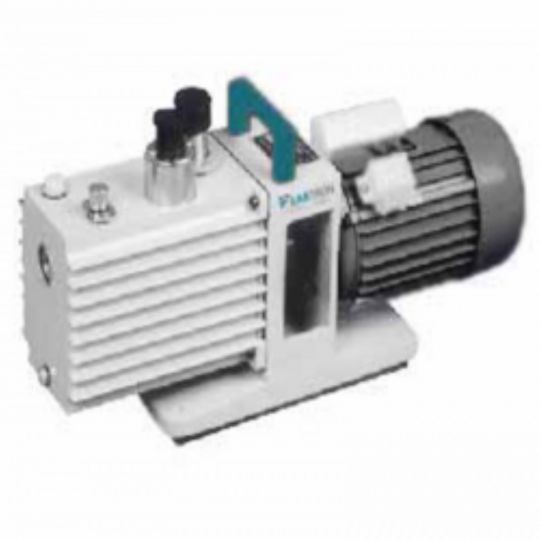
Direct drive rotary vane vacuum pump are especially designed for pumping air from sealed vessels. It offers even, pulse-free air flow, big preliminary torque design that produces less noise or vibrations and is maintenance free. It can also be used as fore-pump, diffusion pump, process pump or molecular pump.for more visit labtron.us
0 notes
Text
SOUZ Vacuum Pump 2X Two-stage Oil Lubricated Rotary Vane vacuum pumps
2X Belt Drive Rotary Vane Pump is almost identical to a Direct Drive Rotary Vane Pump from SOUZ VACUUM. The only difference between the two is that the belt drive Rotary Vane Vacuum Pump is driven by a belt. There are several advantages why a belt drive vacuum pump would be preferable. One of these reasons is that the belt drive Rotary Vane Vacuum Pump runs at a slower RPM therefore the temperature created is lower, the wear and tear is less, and the overall lifetime of the pump is longer.
Belt drive vacuum pump 2X series are equipped with highly durable vacuum pump assembled for pumping air from sealed vessels. It provides ultimate vacuum pressure of ≤ 1Pa.The robust design and high end vacuum makes this belt driven vacuum pump powerful system. It can be used as a stand-alone machine or as a fore-pump, process pump or titanium pump of booster pump, oil diffusion pump and molecular pump.
A choice of versions provides the right variant for every application.
Single stage oil flooded rotary vane vacuum pump : SV008-SV630
Two stage oil lubricated rotary vane vacuum pump : 2XZ-2C~2XZ-25C. T8~T60 ; 2X-4A-2X-100A
Contact us , [email protected]
Find us , www.souzvac.com
0 notes
Text
How does a rotary vane vacuum pump work?
Oil sealed rotary vane vacuum pump working principle
A rotary vane vacuum pump (referred to as a rotary vane pump) is an oil-sealed mechanical vacuum pump. Its working pressure range is 101325~1.33×10⁻² (Pa), which belongs to the low vacuum pump. It can be used alone or as a backing pump for other high vacuum pumps or ultra-high vacuum pumps. It has been widely used in production and scientific research departments such as metallurgy, machinery, military industry, electronics, chemical industry, light industry, petroleum, and medicine.
The rotary vane pump can pump out the dry gas in the sealed container, and if it is equipped with a gas ballast device, it can also pump out a certain amount of condensable gas. But it is not suitable for pumping gas with high oxygen content, corrosive to metal, and chemical reactions to pump oil and dust particles.
The rotary vane pump is one of the most basic vacuum-obtaining equipment in vacuum technology. Rotary vane pumps are mostly small and medium-sized pumps. There are two types of rotary vane pumps: single-stage and two-stage. The so-called two-stage is to connect two single-stage pumps in a series structure. Generally, it is made into two stages to obtain a higher vacuum degree. The relationship between the pumping speed and the inlet pressure of the rotary vane pump is stipulated as follows: when the inlet pressure is 1333Pa, 1.33Pa, and 1.33×10⁻¹ (Pa), the pumping speed value shall not be lower than 95%, 50% and 20%of the nominal pumping speed of the pump.
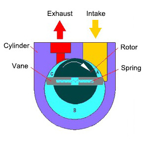
The rotary vane pump is mainly composed of the pump body, rotor, rotary vane, end cover, spring, and so on. A rotor is eccentrically installed in the cavity of the rotary vane pump, the outer circle of the rotor is tangent to the inner surface of the pump cavity (there is a small gap between the two), and two rotary vanes with springs are installed in the rotor slot. When rotating, relying on the centrifugal force and the tension of the spring to keep the top of the rotary vane in contact with the inner wall of the pump chamber, the rotation of the rotor drives the rotary vane to slide along the inner wall of the pump chamber.
The two rotating vanes divide the crescent-shaped space surrounded by the rotor, the pump chamber, and the two end covers into three parts A, B, and C, as shown in the figure. When the rotor rotates in the direction of the arrow, the volume of space A communicating with the suction port increases gradually, and it is in the process of suction. And the volume of space C communicating with the exhaust port is gradually reduced, just in the process of exhausting. The volume of space B in the middle is also gradually decreasing, which is in the process of compression. Since the volume of space A gradually increases (that is, expands), the gas pressure decreases, and the external gas pressure at the inlet of the pump is higher than the pressure in space A, so the gas is inhaled.
When space A is isolated from the suction port, it turns to the position of space B, the gas starts to be compressed, the volume gradually decreases, and finally communicates with the exhaust port. When the compressed gas exceeds the exhaust pressure, the exhaust valve is pushed open by the compressed gas, and the gas passes through the oil layer in the tank and is discharged into the atmosphere. The purpose of continuous pumping is achieved by the continuous operation of the pump.
One stage rotary vane vacuum pump working principle
The single-stage rotary vane pump has only one working chamber, and the pump is mainly composed of a stator, a rotary vane, and a rotor. The rotor is installed eccentrically in the pump chamber, and two rotating vanes are installed in the rotor groove, which is close to the cylinder wall due to the elastic force of the spring (there is also a centrifugal force of the rotating vanes after rotation). The rotor and vanes divide the stator cavity into suction and discharge.
When the rotor rotates in the stator cavity, the volume on the side of the air inlet is gradually expanded periodically to inhale the gas, while the volume on the side of the exhaust port is gradually reduced to compress the inhaled gas and discharge it from the exhaust valve.
The vent valve is immersed in oil to prevent atmospheric air from entering the pump. The vacuum pump oil enters the pump chamber through the oil hole and the exhaust valve so that all the moving surfaces in the pump chamber are covered with oil, forming a seal between the suction chamber and the exhaust chamber.
Two stage rotary vane vacuum pump working principle
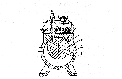
In order to improve the ultimate vacuum of the pump, in addition to improving the machining accuracy of the pump body, rotor, and rotary vane, and minimizing the assembly gap and harmful space, the most effective way is to connect two single-stage pumps in series to form a two-stage pump.
The pump consists of two working chambers. The two chambers are connected in series and rotate in the same direction at the same speed. A chamber is the front stage of B chamber. A is the low vacuum stage and B is the high vacuum stage. The pumped gas enters the front stage through the high vacuum stage (B ), and is discharged out of the pump through the exhaust valve. The front stage (A) is the same as the single-stage pump, oil enters the pump chamber at any time, while the high vacuum stage (B) only has a small amount of oil when it starts to work, and no oil enters the pump chamber after working for a period of time. When the pump starts to work and the pressure of the inhaled gas is relatively high (such as starting to pump air from atmospheric pressure), the gas is compressed through the B chamber, and the pressure increases sharply, and a part of the compressed gas is directly discharged from the auxiliary exhaust valve (1) , and the other part is discharged through the front stage.
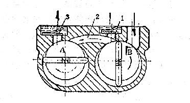
When the pump works for a period of time, when the pressure of the gas inhaled by the B chamber is low, even though it is compressed by the B chamber, the pressure cannot reach above one atmospheric pressure, and the auxiliary exhaust valve 1 cannot be discharged, and all the inhaled gas will enter The front-stage A room is discharged through the exhaust valve 3 through the continuous compression of the A room.
After the pump works for a period of time since the pressure of the high-vacuum stage air intake is greatly reduced, the outlet pressure is also very small, so the pressure difference between the inlet and outlet of the B chamber is also small, and the amount of compressed gas returned is correspondingly reduced; at the same time, the latter stage The oil molecules that are easy to evaporate in the pump are continuously sucked away by the front-stage A chamber, and the partial pressure of the oil vapor is reduced. Therefore, the oil pollution of the two-stage pump is smaller than that of the single-stage pump, and the ultimate vacuum degree will be greatly improved.
1 Stage vs. 2 Stage Rotary Vane Vacuum Pump
1 stage rotary vane pump consists of a single rotor with multiple vanes that rotates within a cylindrical chamber. As the rotor spins, centrifugal force pushes the vanes against the chamber wall, creating a seal and forming variable-volume chambers. The pumping action occurs through the expansion and compression of gas in these chambers, resulting in the generation of a vacuum.
Simplicity: 1-stage pumps have a straightforward design with fewer moving parts, making them compact, lightweight, and easy to operate and maintain.
Cost-Effective: These pumps are typically more affordable compared to 2-stage pumps, making them a cost-effective option for applications that do not require extremely low vacuum levels.
Suitable for Low to Medium Vacuum: 1-stage pumps are ideal for applications that require vacuum levels within the range of approximately 100 to 1,000 mbar (millibar).
Efficient for Low Gas Loads: They perform well when handling low gas loads, making them suitable for applications where gas flow rates are not excessive.
In a 2 stage rotary vane pump, the pumping process is divided into two sequential stages, each with its own set of vanes. The first stage, known as the high-vacuum stage, operates similarly to a 1 stage pump, creating an initial level of vacuum. The gas discharged from the first stage then flows into the second stage, where further compression occurs, resulting in even lower vacuum levels.
Higher Vacuum Levels: 2 stage pumps are capable of achieving significantly higher vacuum levels compared to 1 stage pumps. They can reach vacuum levels as low as 0.1 mbar or even lower.
Improved Gas Handling: These pumps are effective in handling higher gas loads and can efficiently evacuate larger volumes of gas.
Enhanced Backstreaming Resistance: The two-stage configuration provides better resistance to backstreaming, preventing oil or contaminants from reaching the vacuum chamber or system.
Suitable for High Vacuum Applications: 2 stage pumps are well-suited for applications requiring high vacuum levels, such as analytical instruments, vacuum coating, and semiconductor manufacturing.
#rotary vane vacuum pump#two stage rotary vane vacuum pump#rotary vane vacuum pump working principle
0 notes
Text
MEDICAL VACUUM PUMPS FOR HEALTHCARE USE-Rotary Claw Vacuum Pump
MEDICAL VACUUM PUMPS FOR HEALTHCARE USE-Rotary Claw Vacuum Pump
HOME > BLOGS > MEDICAL VACUUM PUMPS FOR HEALTHCARE USE
Medical vacuum pumps in healthcare to provide suction used in the operating rooms, intensive care units and various other clinical uses throughout a facility. There are multiple technologies that can provide the level of suction required for these applications, NFPA 99 requires 16”Hg at the furthest outlet. Facilities should review different factors when selecting a technology for their facility, taking into account, capital costs, maintenance requirements, elevation, and if it will be used for waste anesthetic gas disposal.
TYPES OF VACUUM PUMPS FOR MEDICAL USE
ROTARY CLAW VACUUM PUMPS :
In a pump housing, two claw-shaped rotors take in air as they rotate in opposite directions. The rotors compress the air and discharge them through the silencer. The pumping chamber is dry, and the no-contact rotors eliminate internal wear and parts to replace. A gear synchronizes the rotors and requires a small amount of oil that does not come into contact with the discharge piping.
Rotary Claw Pumps have been designed with efficient technology. This technology delivers the most SCFM/HP. They require extremely low maintenance. There is one quart of seal oil that should be replaced every 6 months - 1 year depending on site conditions. Claws are also the only technology that can be run with variable speed drives (VSD). The VSD has the potential to dramatically reduce the electricity usage, the noise of the pump, and the heat output of the package. VSD should be selected regardless of the HP required to satisfy demand.
For applications of waste anesthesia gas disposal (WAGD), the Claw technology is the only technology allowed by code. If the facility is combining the WAGD with the medical vacuum line, the Claw is still the best choice in meeting code for a dual application.
Potential drawbacks to the Claw technology is it does have the highest initial capital cost. However, once a lifetime cost analysis is completed comparing the other technologies maintenance requirements and costs, it shows to be the least expensive over the life of the package. Another drawback is its limitations at elevation over 5000’ due to it being air driven. At higher elevations, a diversity factor needs to be applied to determine the actual scfm output.
Key Considerations :
Gear Oil Replacement
Good candidate for VFD (energy efficiency alternative)
Vacuum Level considerations 24"Hg
Low Maintenance
Higher Cost of Equipment
Noise Considerations
WAGD evac pump if Fomblin is utilized
Synchronizing Gear Oil
Weekly 5.000 hours/Annually
Check oil
Change oil.
Pump Bearings
2- 8.7 hp
15 hp
Not Required
6 months
Not Required
Grease B side bearings
Motor Coupling
Annually
Remove Motor to inspect coupling for wear.
Replace as needed.
LUBRICATED ROTARY VANE VACUUM PUMPS :
Oil-lubricated rotary vane vacuum pumps are positive-displacement pumps that feature sliding vanes in a rotor rotating within a cavity. An eccentrically mounted rotor with slots rotates in a cylindrical housing and the precisely fitting sliding vanes move in the slots and separate the individual working chambers. Compared to dry-running rotary vane pumps, oil-lubricated pumps additionally seal the working chambers with the oil that is transported. The lubricated vane vacuum pumps can provide long hours of reliable service.
They are less expensive than Claw, but are not as efficient. Potentially requiring more HP to deliver the required scfm. They require frequent maintenance to run optimally. The oil in the chamber needs to be changed a minimum of every 3,000 hours but could be more frequently depending on site conditions. In an average healthcare facility that is often once a quarter and is several quarts of oil. This often makes their life cycle cost higher than the claw after just one year.
Lubricated Rotary Vane Vacuum pumps are not recommended for applications where anesthetizing gases exceed 23% of total vacuum. They are a good solution where the application is over 5000’ elevation as it is not affected.
OIL-LESS ROTARY VANE PUMPS :
In an oil-less rotary vane pump, also referred to as dry vane pump, a rotor is mounted eccentrically. They feature sliding vanes in a rotor rotating within a cavity. The vanes are self-lubricating carbon graphite-filled vane material which does not necessitate lubricant disposal. The vanes themself wear out and will need to be changed when they no longer can keep the rotor running. The vanes increase in size as the HP is increased. For this reason this technology is not offered over 10HP. The vane life decreases as the HP increases.
Oil-less rotary Vane Vacuum pumps are not recommended for applications where anesthetizing gases exceed 23% of total vacuum. They are also not recommended at applications over 5000’ elevation.
Selecting The Best Technology For Your Facility
When selecting a new vacuum system for your facility, you want to compare all technologies to ensure you choose the technology best suited for your requirements. Implementing the proper vacuum system for your healthcare facility is crucial for maintaining optimal performance, profitability, and, most importantly, the safety of your patients and staff.
At Pattons Medical, our team has over 400 years of combined experience. Our medical gas consultants can assist early on in the project and provide their expertise to ensure your vacuum system is designed and installed in accordance with NFPA 99 code while remaining within your budget. Pattons Medical manufactures lubricated vane, dry vane, and rotary claw vacuum systems in Charlotte, North Carolina. Pattons Medical products meet or exceed NFPA 99 and CSA Standards and are UL approved. One of our many strengths is our capability to work with our engineers to develop special packages to help meet particular application or specifications.
0 notes
Text
The 4 Different Kinds of Industrial Vacuum Pumps
Vacuum pumps may be used in various applications and industries. They are used in hospitals, businesses, restaurants, and other establishments. Regardless of the application, there are undoubtedly industrial vacuum pumps that meet your needs.
Below is a brief description of each vacuum pump for industrial use that can help you decide which option best fits your needs. That being said, you should always contact a vacuum pump expert if you have any questions.
Rotating Vane
This vacuum pump for industrial use is available in several high-capacity variants and can meet varying demand levels. The automotive and aerospace sectors use rotary vane vacuums the most. With a check valve and a direct-drive NEMA motor, the horsepower of these machines range from 1.5 to 10.
The first rotary vane vacuum pump was invented in 1874 by New Brunswick inventor Charles Barnes. It features a rotor that rotates inside a huge, circular chamber. The chambers of the vanes are generated by motion.
Reciprocating Vacuum Pump For Industrial Use
A reciprocating pump is among the oldest and most trustworthy pump technologies. Today, they are fabricated from a variety of materials and used for a variety of purposes. They are used in the chemical, petrochemical, pharmaceutical, & cosmetics industries.
A reciprocating vacuum pump has an efficiency of around 90 percent and is exceptionally durable. They are suited for low-flow, high-pressure applications like water jet cutting.
Dry Claw Vacuum Pump For Industrial Use
Due to their durability and effectiveness, dry claw vacuum pumps for industrial use are used in packaging, printing, wood processing, and wastewater treatment.
These pumps have a high degree of performance, produce little noise, and are considered safe. They use a pair of rotors that revolve in opposing directions without coming into touch. These pumps are the best option due to their superior performance and longevity.
Liquid Ring
There are several uses for liquid ring vacuum pumps, including paper manufacture, petroleum refining, and soil remediation. Companies may also use them to remove water from paper-making machines and non-condensable gas from steam turbine generators. Additionally, they may shape egg cartons and related paper items.
These devices are good for dealing with vapor loads. They are perfect for handling wet or dry gases that, include liquid.
Find the Right Vacuum Pump for You
There is a vacuum pump suitable for your company, regardless of the industry you operate in or the application required. If you are looking for high-quality industrial vacuum pumps and systems, there are several options available, such as the multinational company Atlas Copco.
1 note
·
View note
Text
Oilfield Companies Superior Industrial Providers
Avacuum truckis a tank truck with a heavy responsibility vacuum designed to pneumatically load solids, liquids, sludge or slurry through suction strains sometimes 2-4″ in diameter with 3″ being the norm. The typical pump used in the industry is the rotary vane vacuum pump. The truck may vacuum truck oilfield be configured to be a direct belt drive, or a hydraulic drive system. There are two alternative ways to mount the pump either directly on the truck with the vacuum drive powered by the truck motor, or on the trailer with an independent motor.
That is why it is troublesome to provide a uniform estimate of how a lot totally different variants of these vehicles would cost without having the necessary data on the truck itself. Reach out to Curry Supply at your convenience and allow us to give you an oilfield vacuum truck that's suitable for high-intensity operations, meets your distinctive wants, and fits your finances. We ship our products globally, helping our clients from all parts vacuum truck oilfield of the us run their businesses smoothly and improve their revenue by boosting revenues and reducing maintenance costs. Vacuum vehicles, also identified as vacuum tankers, are often utilized by cities to deal with large-scale liquid and sludge clear up, most commonly in sewer and septic system upkeep. They can be utilized in industrial and municipal settings to suction water and debris left from hydro-excavation or drilling jobs.
Key’s vacuum vans transport non-hazardous fluid or waste to or out of your well operation. We have six 70 barrel vacuum trucks with strain pumps, and two tanker vehicles prepared to supply transportation and disposal of hazardous and non-hazardous materials, liquids, solids, and sludges. Vacuum truck operators in the oil and gasoline industry face a spread of hazards, says Budd Phillips, manager of prevention field companies for Fort St. John at WorkSafeBC. Workers are handling liquids that are toxic and corrosive, and harmful vacuum truck oilfield fumes are released from the liquid waste of oil and gas wells as it's sucked up into the truck. One such gas is H2S, which in low levels may cause eye irritation, nausea and dizziness and in excessive levels may cause unconsciousness or dying. Sometimes a chemical unexpectedly mixes with another to provide a harmful substance; for instance, when hydrochloric acid is added to the residue of other merchandise in a tank it may possibly release fumes, which can be deadly.
Conditions and terrain are about as dangerous as it gets within the business. Most areas are too difficult to entry by transport trailer, so most liquids transport is completed by vacuum truck tank. His duties included all Sales, Daily Field Operations, Dispatch Centers and Shop facilitates. He had direct involvement in Motor Vehicle Safety processes together with journey management and DOT requirements, gear backing and securement policies and in 2007 was licensed in LEAN Six Sigma.
0 notes
Text
WHAT IS PNEUMATICS?
Pneumatic systems are widely used in machines, engines, and industrial applications. Air or gas is used in every pneumatic system to move an actuator, and can be as simple as an air-driven piston, or as complex as a mining operation with many actuators. In most cases, atmospheric air is used for compression; there is plenty of it, and it is free. Since pneumatic systems are quieter, cheaper to run, and easier to use, they are generally preferred over hydraulic systems in industry and manufacturing.
What Is Pneumatics?
Pneumatics refers to both the physical science of compressing air and to the branch of mechanical engineering that deals with compressed air or gas. Originally, pneumatics was as simple as taking a deep breath, compressing the air in your lungs, then blowing it out forcefully to ignite a fire or fire a dart from a tube. Pneumatics derives from the ancient Greek word for blowing, pneuma, and the same root form also appears in the English word pneumonia.
Common Parts Of A Pneumatic System
Drives
Valves
Fittings
Tubing & Hoses
Vacuum Technology
Air Preparation (Filters, Regulators & Lubricators)
Silencers
DRIVES/CYLINDERS
Using pneumatics, force is converted into potential energy, which is then converted into kinetic energy and used to drive actuators or cylinders. Typically, piston rods are used or other forms of actuation, such as 'rodless', are used for linear motions. Using either a single action or a double-action stroke, the piston rod produces an up-and-down or back-and-forth motion.
Single-acting pneumatic cylinders drive the piston rod linearly only in one direction. By expelling the compressed air, a vacuum is created, which allows the piston rod to return via a mechanical spring. By manipulating compressed air with valves, double-acting cylinders allow the load to move in a push-pull motion. As a result, the stroke length can be increased, as well as constant force can be maintained on alternating movements.
Several different types of rodless cylinders are available, including linear slides, magnetic couplings, inflatable bellows, and rotary vane pumps. In applications requiring long strokes or high-moment loads, they are usually located on a carriage alongside the piston.

VALVES
There are many functions that valves perform in pneumatics, including controlling and directing airflow. You can start up the system with a soft start or an on-off valve, and you can control the rate of airflow with flow control valves. Flow direction can be controlled by ball valves and angle seat valves, and a secondary system can be controlled by pilot valves.
Venting the system requires an exhaust valve. You'll need a shut-off valve to shut it down, and a safety dump valve to initiate an emergency stop. At specified intervals, these types of valves release air pressure from the system.
To direct or position the flow of air into the pneumatic system, simple air valves require some motivating force. When this force is applied directly to the operating medium, it is a direct-operated valve rather than a pilot or secondary valve. One of the simplest valves is the two-position flow control valve, which is either on or off.
The flow and directional control valves are self-explanatory, but some versions allow three-way directional control from the inlet to two outlets, and the more complex four-way valve. This allows the flow to be directed from the inlet to a choice of three outlet ports. Based on the flow rate or pressure of the inlet, proportional valves are electronically controlled using solenoids. Fluid pressures and flows must be distributed in varying ratios when using this type of valve with one or more outputs.
In modern pneumatics, solenoid valves are also increasingly common, and today's complex systems have given rise to universal valve terminals that enable modular valve configurations. So that many advanced and specific situations can be controlled simultaneously, the choice and use of valves have become quite a complicated undertaking.
FITTINGS
A pneumatic system consists of many components that need to be connected using fittings. Connecting the major system components with hoses, pipes, and tubes, pneumatic fittings conduct compressed air to the application's active components. Since the whole system operates under compressed gas or air pressure, all its components must fit together properly and be leak-proof.
The types and sizes of fittings vary, as well as the materials used, and the way they are connected. Even though other materials such as polymers are now being used, metal screw-in threads still provide the strongest bond. Using compression fittings, you can join pipes of different sizes or types, while barb fittings are most often used to join flexible tubing. There is a threaded end that connects to the pipe and a barbed cone that goes into the tube. For joining air hoses, many people prefer push-in fittings, which are often used in modern technology. Its quick connect-and-disconnect design makes it easy to change parts, and it comes in a variety of sizes and materials.
TUBING AND HOSES
There is a difference between tubing and hoses in a pneumatic system: hoses are typically used in high-pressure applications and are reinforced for extra strength; tubing, on the other hand, is used in low-pressure applications and does not require reinforcement. A flexible pneumatic hose or tubing is more widely used than a rigid one, and they are available in many different types. In pneumatic systems, flexible tubes and hoses are the most versatile components due to the development of strong polymers and application-specific materials. All you need to do is ensure that your hoses and tubing are the right size and type for your devices.
VACUUM TECHNOLOGY
In the presence of a vacuum, the air pressure is substantially below atmospheric pressure, specifically 300 bar or less. From rough vacuum to ultra-high vacuum, the available vacuum range can be divided into four categories. Vacuums are created by removing all the air from a contained space using a vacuum generator connected to your pneumatic system. A diffuser ejects compressed air forcibly, leaving a vacuum in the application. A suction pad or cup will be used to draw up the item on the workspace into the vacuum, where it will be gripped while being processed.
Modern industry and various manufacturing processes make use of vacuum technology, including food and beverage production, pharmaceuticals, metallurgy, and process engineering. Generally, they are used for delicate pick-and-place applications, such as plate glass and small electronic components, or for holding items in place. Probably the most well-known application of this technology is vacuum packaging.
AIR PREPARATION
Compressed air becomes hot, then cools again, producing condensation which contaminates the compressed air supply. Impurities such as dirt, dust, oil, and other particulates are also commonly found in atmospheric air. If compressed air containing such contaminants passes downstream into parts of the pneumatic system, such as cylinders, valves, and hoses, some damage is inevitably caused. The fittings and components along the compressor's outward journey to the application can contribute to further contamination, even if your compressor has filters, dryers, or regulators built in.
Your compressed air supply must be filtered to ensure that your system functions properly for as long as possible. A simple air filter can be installed for this purpose, but air pressure must still be monitored to ensure that the correct pressure is maintained. Furthermore, compressed air needs to be lubricated so that downstream equipment is not damaged by excessively dry air. Filtering, regulation, and lubrication can be handled by separate units, but it's more common to install a combined Filter-Regulator-Lubricator unit (FRL).
You should prepare the air at the point of use for your pneumatic system to ensure optimal performance. It is particularly important if the compressor is far away and there are opportunities for water and particulates to accumulate en route. In today's world, FRL units provide a comprehensive range of filtration options, operating pressure regulation, and lubrication options. Space-saving and cost-effective, they will extend the life of your pneumatic system if properly sized and installed.
SILENCERS
The purpose of pneumatic air silencers is to reduce excess noise when air is exhausted from your pneumatic system, similar to that of car exhaust silencers. When the exhaust air from a pneumatic system is vented, it often makes an explosive sound, depending on the force and pressure. Increasing the operational noise levels of the application as a whole can cause physical damage or disturbance to personnel. Adding a silencer to pneumatic cylinders, 5/2-way solenoid valves, or other associated devices is a cost-effective solution.
Furthermore, silencers can control the amount of airflow out of the unit with throttle valves that can be adjusted. In addition to controlling actuator speed, they also function similarly to needle valves. To protect the environment from harmful particulates, an exhaust cleaner may also be added to the silencer unit to clean the exhaust air.
Airmax Pneumatics is the leading air preparation unit manufacturer. India. We offer various types of industrial valves like pneumatic valves, pneumatic cylinders, and many more.
0 notes
Text
Kalbro Industrial Pumps
The cornerstone of Kalbro Manufacturing Co. was laid down in the year 1982. Since then, the company has made remarkable recognition in the international as well as in the domestic market for its world-class products. The company is leading manufacturers, suppliers & exporters of a comprehensive range of products. Our product range includes Dry Vacuum Pumps, Belt Driven Rotary Vane High Vacuum Pumps, Direct Drive Rotary High Vacuum Pumps, Diaphragm Vacuum Pumps, Water Ring Vacuum Pumps, and Side Channel Blowers.
These pumps are widely used in several industries like chemical, pharmaceutical, oil refinery, automobiles, petrochemical, and several others. Our products are based on imported technology so that these offer high performance during operation.

Manufacturing Unit
We manufacture our pumps and other industrial products at our in the house manufacturing facility which is located in Haryana, India. Our state of the art facility is loaded with advanced machinery and technology. This helps us in manufacturing products in compliance with international standards.
Quality Assurance
We have also set up a quality maintenance cell. Our competent professionals test our products on a regular basis during production to offer world-class quality in our products.
Features of Kalbro Pumps
1 - Excellent Quality
2 - Durability
3 - Reliability
4 - Based on power saving technology
5 - Low maintenance
Contact Kalbro
For any kind of query, contact us with the details below -
(Phone) +91-9953028326 / +91-84590 27350
(Email) [email protected]
(Address) B-8, Nehru Ground, N.I.T. Faridabad - 121 001, Haryana.
#industrialpumps #vacuumpumps
1 note
·
View note
Photo

What kind of vacuum pump is used widely in freeze industry?Let us choose the Double stage oil rotary vane #vacuumpump 2XZ model. Direct drive,compact design ,efficient . Find your interested model in our website:www.souzvac.com #vacuumpumps #vacio #pumper #vacuumservice #souzvacuumpump #freezedryer https://www.instagram.com/p/CeBbyJCpgqn/?igshid=NGJjMDIxMWI=
0 notes
Text
Useful information on External Gear Pumps
A gear pump is a type of positive displacement (PD) pump. Gear pumps use the actions of rotating cogs or gears to transfer fluids. The rotating gears develop a liquid seal with the pump casing and create a vacuum at the pump inlet. Fluid, drawn into the pump, is enclosed within the cavities of the rotating gears and transferred to the discharge. A gear pump delivers a smooth pulse-free flow proportional to the rotational speed of its gears.
There are two basic designs of gear pump: internal and external (Figure 1). An internal gear pump has two interlocking gears of different sizes with one rotating inside the other. An external gear pump consists of two identical, interlocking gears supported by separate shafts. Generally, one gear is driven by a motor and this drives the other gear (the idler). In some cases, both shafts may be driven by motors. The shafts are supported by bearings on each side of the casing.
This article describes plastic gear pump in more detail.
There are three stages in an internal gear pump’s working cycle: filling, transfer and delivery (Figure 2).
As the gears come out of mesh on the inlet side of the pump, they create an expanded volume. Liquid flows into the cavities and is trapped by the gear teeth as the gears continue to rotate against the pump casing.
The trapped fluid is moved from the inlet, to the discharge, around the casing.
As the teeth of the gears become interlocked on the discharge side of the pump, the volume is reduced and the fluid is forced out under pressure.
No fluid is transferred back through the centre, between the gears, because they are interlocked. Close tolerances between the gears and the casing allow the pump to develop suction at the inlet and prevent fluid from leaking back from the discharge side (although leakage is more likely with low viscosity liquids).
External gear pump designs can utilise spur, helical or herringbone gears (Figure 3). A helical gear design can reduce pump noise and vibration because the teeth engage and disengage gradually throughout the rotation. However, it is important to balance axial forces resulting from the helical gear teeth and this can be achieved by mounting two sets of ‘mirrored’ helical gears together or by using a v-shaped, herringbone pattern. With this design, the axial forces produced by each half of the gear cancel out. Spur gears have the advantage that they can be run at very high speed and are easier to manufacture.
Gear pumps are compact and simple with a limited number of moving parts. They are unable to match the pressure generated by reciprocating pumps or the flow rates of centrifugal pumps but offer higher pressures and throughputs than vane or lobe pumps. External gear pumps are particularly suited for pumping water, polymers, fuels and chemical additives. Small external gear pumps usually operate at up to 3500 rpm and larger models, with helical or herringbone gears, can operate at speeds up to 700 rpm. External gear pumps have close tolerances and shaft support on both sides of the gears. This allows them to run at up to 7250 psi (500 bar), making them well suited for use in hydraulic power applications.
Since output is directly proportional to speed and is a smooth pulse-free flow, external gear pumps are commonly used for metering and blending operations as the metering is continuous and the output is easy to monitor. The low internal volume provides for a reliable measure of liquid passing through a pump and hence accurate flow control. They are also used extensively in engines and gearboxes to circulate lubrication oil. External gear pumps can also be used in hydraulic power applications, typically in vehicles, lifting machinery and mobile plant equipment. Driving a gear pump in reverse, using oil pumped from elsewhere in a system (normally by a tandem pump in the engine), creates a motor. This is particularly useful to provide power in areas where electrical equipment is bulky, costly or inconvenient. Tractors, for example, rely on engine-driven external gear pumps to power their services.
External gear pumps can be engineered to handle aggressive liquids. While they are commonly made from cast iron or stainless steel, new alloys and composites allow the pumps to handle corrosive liquids such as sulphuric acid, sodium hypochlorite, ferric chloride and sodium hydroxide.
What are the limitations of a gear pump?
External gear pumps are self-priming and can dry-lift although their priming characteristics improve if the gears are wetted. The gears need to be lubricated by the pumped fluid and should not be run dry for prolonged periods. Some gear pump designs can be run in either direction so the same pump can be used to load and unload a vessel, for example.
The close tolerances between the gears and casing mean that these types of pump are susceptible to wear particularly when used with abrasive fluids or feeds containing entrained solids. External gear pumps have four bearings in the pumped medium, and tight tolerances, so are less suited to handling abrasive fluids. For these applications, universal gear pump are more robust having only one bearing (sometimes two) running in the fluid. A gear pump should always have a strainer installed on the suction side to protect it from large, potentially damaging, solids.
Generally, if the pump is expected to handle abrasive solids it is advisable to select a pump with a higher capacity so it can be operated at lower speeds to reduce wear. However, it should be borne in mind that the volumetric efficiency of a gear pump is reduced at lower speeds and flow rates. A gear pump should not be operated too far from its recommended speed.
For high temperature applications, it is important to ensure that the operating temperature range is compatible with the pump specification. Thermal expansion of the casing and gears reduces clearances within a pump and this can also lead to increased wear, and in extreme cases, pump failure.
Despite the best precautions, gear pumps generally succumb to wear of the gears, casing and bearings over time. As clearances increase, there is a gradual reduction in efficiency and increase in flow slip: leakage of the pumped fluid from the discharge back to the suction side. Flow slip is proportional to the cube of the clearances between the cog teeth and casing so, in practice, wear has a small effect until a critical point is reached, from which performance degrades rapidly.
Gear pumps continue to pump against a back pressure and, if subjected to a downstream blockage will continue to pressurise the system until the pump, pipework or other equipment fails. Although most gear pumps are equipped with relief valves for this reason, it is always advisable to fit relief valves elsewhere in the system to protect downstream equipment.
The high speeds and tight clearances of external gear pumps make them unsuitable for shear-sensitive liquids such as foodstuffs, paint and soaps. Internal gear pumps, operating at lower speed, are generally preferred for these applications.
What are the main applications for gear pumps?
External gear pumps are commonly used for pumping water, light oils, chemical additives, resins or solvents. They are preferred in any application where accurate dosing is required such as fuels, polymers or chemical additives. The output of a gear pump is not greatly affected by pressure so they also tend to be preferred in any situation where the supply is irregular.
Summary
An external gear pump moves a fluid by repeatedly enclosing a fixed volume within interlocking gears, transferring it mechanically to deliver a smooth pulse-free flow proportional to the rotational speed of its gears.
External gear pumps are commonly used for pumping water, light oils, chemical additives, resins or solvents. They are preferred in applications where accurate dosing or high pressure output is required. External gear pumps are capable of sustaining high pressures. The tight tolerances, multiple bearings and high speed operation make them less suited to high viscosity fluids or any abrasive medium or feed with entrained solids.
External-gear pumps are rotary, positive displacement machines capable of handling thin and thick fluids in both pumping and metering applications. Distinct from internal-gear pumps which use “gear-within-a-gear” principles, external-gear pumps use pairs of gears mounted on individual shafts. They are described here along with a discussion of their operation and common applications. For information on other pumps, please see our Pumps Buyers Guide.
Spur gear pumps
Spur gear pumps use pairs of counter-rotating toothed cylinders to move fluid between low-pressure intakes and high-pressure outlets. Fluid is trapped in pockets formed between gear teeth and the pump body until the rotating gear pairs bring individual elements back into mesh. The decreasing volume of the meshing gears forces the fluid out through the discharge port. A relatively large number of teeth minimizes leakage as the gear teeth sweep past the pump casing.
Spur gear pumps can be noisy due to a certain amount of fluid becoming trapped in the clearances between meshing teeth. Sometimes discharge pockets are added to counteract this tendency.
Spur gear pumps are often fitted with sleeve bearings or bushings which are lubricated by the fluid itself—usually oil. Other fluids that lack oil’s lubricity generally demand more stringent pump designs, including locating bearings outside of the wetted cavities and providing appropriate seals. Dry-running bearings are sometimes used. The use of simply-supported shafts (as opposed to cantilevered arrangements seen in many internal gear designs) makes for a robust pump assembly capable of handling very thick liquids, such as tar, without concern for shaft deflection.
Helical gear pumps
Similar to the spur gear pump, the helical gear pump uses a pair of single- or double-helical (herringbone) gears. Helical gears run quieter than spur gears but develop thrust loads which herringbone gears are intended to counteract. These designs are often used to move larger volumes than spur gear pumps. Helical gears produce fewer pulsations than stainless gear pump as the meshing of teeth is more gradual compared with spur-gear designs. Helix angles run between 15 and 30°.
Both the helical and herringbone gear pumps eliminate the problem of trapping fluid in the mesh. These designs can introduce leakage losses where the teeth mesh, however, unless very tight tooth clearances are maintained. The higher manufacturing costs associated with herringbone gear pumps must be balanced against their improved performance.
Applications
External-gear pumps can pump fluids of nearly any viscosity, but speed must normally be reduced for thicker materials. A typical helical gear pump might run at 1500 rpm to move a relatively thin fluid such as varnish but would have to drop its speed nearer to 500 rpm to pump material as thick as molasses in July.
External-gear pumps generally are unsuited for materials containing solids as these can lead to premature wear, although some manufacturers make pumps specifically for this purpose, usually through the use of hardened steel gears or gears coated with elastomer. External-gear pumps are self-priming and useful in low NPSH applications. They generally deliver a smooth, continuous flow. In theory, at least, they are bi-directional. They are available as tandem designs for supplying separate or combined fluid-power systems.
These pumps are capable of handling very hot fluids although the clearances must be closely matched to the expected temperatures to insure proper operation. Jacketed designs are available as well.
External-gear pumps see wide applications across many industries: food manufacturers use them to move thick pastes and syrups, in filter presses, etc.; petrochemical industries deploy them in high-pressure metering applications; engine makers use them for oil delivery. They are used as transfer pumps. Special designs are available for aerospace applications. Pumps for fluid power will conform to SAE bolt-hole requirements.
External-gear pumps are manufactured from a variety of materials including bronze, lead-free alloys, stainless steel, cast and ductile iron, Hastelloy, as well as from a number of non-metals.
External-gear pumps can be manufactured as sanitary designs for food, beverage, and pharmaceutical service. The gears can be overhung, supported by bearings outside the housing with a variety of seals and packings available. Access to these internal pump components through a cover plate makes sanitizing straightforward. Gears are commonly manufactured from composites of PTFE and stainless steel as well as other plastics. Close-coupled and sealless designs are available.
External gear pumps are the least costly of the various positive-displacement pumps but also the least efficient. Pressure imbalances between suction and discharge sides can promote early bearing wear, giving them somewhat short life expectancies.
One general disadvantage that all heat preservation gear pump share over some other positive-displacement pump styles – vane pumps, for instance – is their inability to provide a variable flow rate at a given input speed. Where this is a requirement, a work-around is to use drives capable of speed control, though this is not always a practical solution.
Finally, while rotary, positive-displacement pumps are capable of pumping water, their primary application is in oils and viscous liquids because of the need to keep rubbing surfaces lubricated and the difficulty in sealing very thin fluids. For most applications where water is the media, the centrifugal, or dynamic-displacement pump, has been the clearer choice.
0 notes
Text
Causes and hazards of emulsification of vacuum pump oil
The emulsification phenomenon of vacuum pump oil can be understood in this way from the perspective of physics. Because of the effect of surfactant, the phenomenon that two liquids that can not be mixed together can be mixed together is called emulsification phenomenon. Today, I'd like to talk about the causes and hazards of vacuum pump oil emulsification.
Vacuum pump
reason:
During the operation of vacuum pump, corrosive gas or gas containing water vapor may be inhaled. Then the corrosive gas will corrode the metal parts inside the pump, and react with the vacuum pump oil. The gas containing water vapor will also cause the vacuum pump oil to emulsify.
influence:
The use of vacuum pump is very wide, from the reason of vacuum pump oil emulsification, in the process of medicine, food, ceramics and other industries, it is easy to emulsify. Because in the process of vacuum dehydration, a lot of water vapor will be discharged into the pump oil, which can not avoid the vacuum pump oil being emulsified.
harm:
The emulsification of vacuum pump oil not only affects the service life of pump oil, but also affects the deterioration of pressure. This is one of the common faults of vacuum pump. The normal operation of the vacuum pump is seriously affected.
Methods to prevent emulsification of vacuum pump oil:
It is the simplest way to choose the pump oil for anti emulsification. The pump oil has good anti emulsification and strong oil separation ability. Steam and condensate gas can be partially eliminated by opening the gas valve. You just need to remember that low viscosity pump oil is more demulsifying than high viscosity pump oil. The effect of adding pump oil is more obvious than that of not adding pump oil.
Cleanliness of vacuum pump oil:
(1) The oil filling window must be clean and tidy. It is strictly forbidden to be exposed to the sun and stored in the open air. It should be stored in a dark, dry and ventilated place to prevent mixing of moisture and dust.
(2) The refueling appliance must be a special equipment, not a container containing other oil or solvent; Suction pump.
(3) When taking or loading the oil, the light rain around the end of the barrel must be cleaned to prevent the impurities from mixing into the oil and causing the wear of the pump.
(4) When changing the oil of the vacuum pump, the unused oil in the pump must be cleaned. Pour the new oil into the pump, slowly rotate the pump shaft, clean the remaining oil in the pump chamber, and repeat the cleaning.
(5) When mineral oil is exchanged with ester oil or other synthetic oil, the pump should be disassembled for thorough cleaning, including that every part must be immersed in ester oil to prevent contamination.
Related products:
Oil type rotary vane vacuum pump -- direct drive and belt type drive
0 notes
Text
ZENY 3,5CFM Single-Stage 5 Pa Rotary Vane Economy Vacuum Pump
ZENY 3,5CFM Single-Stage 5 Pa Rotary Vane Economy Vacuum Pump
Excessive Effectivity and Low Noise, Heavy-duty Aluminum Alloy Casing, Oil Drain Plug Positioned at Backside of Oil Reservoir,Inside Excessive Quantity Cooling Fan for Prolonged U(*3*)
Exhaust Port with Exhaust Cap, Direct Drive Motor Permitting Simple Beginning Which is Upkeep Free(*3*)
Oil Sight Glass For Monitoring Oil Ranges, ON/OFF Swap(*3*)
Non Slip Cushion Deal with, Comes With a Bottle of…
View On WordPress
0 notes
Text
Water ring vacuum pump has strong corrosion resistance
Compared with the most common SK series water ring vacuum pump, water ring vacuum pump has the characteristics of strong corrosion resistance, high limit vacuum degree and large exhaust volume. It is widely used in food, petroleum, chemical industry, metallurgy and other professional fields, and can also pump various gases and corrosive gases without solid particles.
There are two main shock absorption methods: the transmission system is reformed. In order to reduce the vibration intention of the motor and transmission shaft, SK water ring vacuum pump is used to transfer the rigid connection with the transmission shaft into elastic connection. The elastic sleeve pin coupling is used to adjust the maximum compensation displacement and compensation angle, so that the vibration of the motor and drive shaft can be compensated through the elastic coupling and will not be directly transmitted to sk water ring vacuum pump.
Considering that it is difficult to reinforce SK water ring vacuum pump, the method of welding "reinforcing rib" in the outlet steel pipe is adopted. Along the inlet and outlet direction, the flange at both ends of the connecting steel pipe between the outlet pipe of SK water ring vacuum pump and the outlet valve can be consulted by the seller for welding with several steel plates of specified thickness and width. The stiffness of steel pipe is added to reduce deformation and resist displacement.
Roots Blower Can Transport Gas
Rotary Vane Vacuum Pump
Dry Scroll Vacuum Pump
0 notes
Text
SVC: Higher Pumping Capacity at Much Lower Pressure When Vacuum Pump Used

SVC was established based on advanced technology and management philosophy of value creation with customers and SVC is a specialized company which manufactures the world highest level vacuum pump and vacuum pumping system.
Screwstar Dry pumps are designed under SVC’s unique screw profile engineering to fulfil wide range of chemical and industrial processes by rotating a paired screw that efficiently admit gases from inlet into the pump inside and compress through the screws swept volume toward the discharge.
Dry Screw vacuum Technology
Screw Vacuum pumps are Rotary Vane type with great fixing course of action. The vanes are sliding sort with spring stacked mounted at 180 separated on to a round and hollow turning part. The siphons clears the air from siphon in take to the fumes through N.R.valves at exhaust port. The notoriety of this cycle of expelling air on any gas from a framework or any vessels brings about the production of high Vacuum. A productive oil dissemination framework gave in the siphon serves to seal the siphon from climate just as to grease up every single mechanical part Screw type vacuum pump machine
SVC exports new technology Screwstar to global markets such as USA, EU, China and India. SVC is doing its b best to give customer satisfaction to the industry of Petrochemical, Fine Chemical, Pharmaceutical, Tank Terminal, Steel, Shipbuilding, Electronics, Semi-conductors Screw type vacuum pump korea
Features
· High Vacuum Roots – EH Series
· EH Vacuum booster allows the booster to be run at atmospheric pressure resulting in total pump down time can be reduced by as much as 50%
· EH boosters lead to cost saving of driving cost and driving time that is, by using hydrokinetic drive, by-pass line and pressure control switch is not needed
· Continuous Operation available at all pressures
· Available to use Backing pump with lower capacity leads to saving cost of early expense to install more than conventional Direct Drive by the intercooler at the outlet
· Automatic Speed Control function
· Protect motors from Overload, Overheating
· Start up with backing pump without any problem
0 notes
Text
Laboratory Vacuum Pumps Market worth US$1,165.2 by the end of 2025
A freshly-compiled business intelligence study by Transparency Market Research (TMR) has notified that the shares in the global laboratory vacuum pump market is distributed among a small chunk of players who operate at the international level. However, the players of this market cannot afford to stay ahead of the curve merely on the back of their existing products, as innovation is essential to maintain the stronghold. Innovative products are being launched consistently to ideally meet the manufacturing and research processes of diverse industries that rely on vacuum systems. According to the lead analyst of the TMR report, laboratory vacuum pumps that are reliable while operating for longer periods of time are gaining adoption, and the future may very well be with equipment that are smaller as well as generate minimal noise, heat, and vibration. In addition to that, technological advancements are also expected in the direction of higher shaft speeds and pumping mechanisms. Companies are also anticipated to use novel materials and enhance design in order reduce operational costs.
Global Laboratory Vacuum Pump Market to be worth US$2,451.0 mn by 2025
As per the estimations of the TMR report, the demand in the global laboratory vacuum pump market will multiply at a CAGR of 4.8% during the forecast period of 2017 to 2025. Revenue-wise, the lucrativeness of the market is primed to expand from US$1,686.9 mn in 2017 to US$2,451.0 mn in 2015, whereas volume-wise, the analysts have projected a requirement of more than 4.5 million laboratory vacuum pump by the end of 2025. The report identifies Welch Vacuum - Gardner Denver, Atlas Copco AB, EBARA Corporations, ULVAC, Inc, Wenling Tingwei Vacuum Equipment Co, KNF Group, Edwards Limited, Pfeiffer Vacuum, Oerlikon Leybold Vacuum GmbH, Tuthill Corporation, Graham Corporation, Sterling SIHI GmbH, and Dekker Vacuum Technologies, Inc. as some of the key players in the global laboratory vacuum pump market.
Based on product type, the report segments the market for laboratory vacuum pump into dry and rotary vane vacuum pump. While both the segments are currently producing substantial demands, the latter is expected to expand at a stronger growth rate until 2025. However, the former requires fewer maintenance measures and hence offer sustained demand. Geographically, North America has been highlighted as the region of maximum profitability, promising to offer a demand worth of US$1,165.2 mn by 2025. However, the demand from the region of Asia Pacific is estimated to expand at an above-average CAGR of 5.3% during the forecast period of 2017 to 2025. Rapid industrialization in the emerging economies of China and India is the primary driver of APAC laboratory vacuum pump market.

View exclusive Global strategic Business report - https://www.transparencymarketresearch.com/laboratory-vacuum-pumps-market.html
Advent of Cost-effective Vacuum Pumps Driving Demand
The global laboratory vacuum pump market is gaining traction from consistent demand by a number of industries pertaining to biotechnology, semiconductor, pharmaceutical, chemical, power, oil and gas, and others. These industries utilize vacuum pumps for various applications that require pressure creation and filtration. In addition to that, technological advancements that have made vacuum pumps a cost-effective equipment for diverse applications is reflecting positively on the incrementing demand. On the other hand, the cost of raw materials has been increasing at a high rate in the recent past and the fluctuations are expected to sustain in the near future too. This is the primary restraint over the global laboratory vacuum pump market.
Key Takeaways:
In terms of volume, over 4.5 million laboratory vacuum pumps to be required by 2025
Leading market players consistently evolving their products to meet diverse demands
Fluctuations in raw material prices obstructing market’s prosperity.
The information presented in this review is based on a Transparency Market Research report, titled, “Laboratory Vacuum Pumps Market (Product Type – Dry Vacuum Pumps and Rotary Vane Vacuum Pumps] – Global Industry Analysis, Size, Share, Growth, Trends, and Forecast, 2017 – 2025.”
Request for covid19 Impact Analysis - https://www.transparencymarketresearch.com/sample/sample.php?flag=covid19&rep_id=39986
0 notes
Text
Technical paper: Vacuum technology in the chemical industry for producing Polyurethanes and Polyisocyanates

The chemical industry is a supplier of indispensable raw materials for many industries. Not only the automotive and engineering industries, for example, but also the plastics, food, glass and building material industries rely on basic chemicals produced by the chemical industry. By far the most important role is played by polyurethane plastics or resins, which serve as the basis for foams or paints. These substances are employed in countless finished products that we use on a daily basis. Vacuum technology is indispensable for a large part of these applications.
For the production of high-quality foams, it requires medium vacuum conditions up to 0.05 hPa
Polyurethanes are compounds which are formed in a polyaddition reaction from multiple alcohols (di-, tri- or polyols) and polyisocyanates. Depending on the basic components used, thermosetting plastics, thermoplastics or elastomers are obtained which differ greatly in their properties and can accordingly be used in a large number of different end products. In the EU alone, more than 2 million tons of polyurethanes are produced annually; global demand rises on average by 5 % per year.
Polyisocyanates are highly reactive organic compounds and act as crosslinkers for two-component polyurethane, from which coatings and foams are formed. The targeted curing of the substance at room temperature and the use of a special coating device, allow to customize the curing time for the application. For example, in a production plant, coatings only need to be mixed if needed immediately.
Vacuum technology is enormously important for the polyisocyanate production. Following the actual production of the isocyanate, the highest possible concentration is ensured by means of a multi-stage distillation process. It requires fine vacuum conditions, i.e., absolute pressures in the range of 0.05 hPa.
ATEX certified vacuum solutions for the production of polyisocyanates
TDI (2,4-toluene diisocyanate), which besides MDI (methylene diphenyl di-isocyanate) is the most widely-produced polyisocyanate in the world, is not only a very toxic liquid, but can also be used at higher temperatures to form flammable vapor- air mixtures. For this reason, the operators of the systems preferably use vacuum pumping stations which are certified in accordance with the ATEX Directive 2014/34/EU and which also meet particularly stringent requirements for tightness.
In order to cover all aspects of quality and safety in the process operation, exact configuration according to the specific requirements of the respective application is necessary. In the first step, the respective gas volume flows are calculated on the basis of substance data and flows in the process. The results then serve as parameters for selecting the appropriate vacuum pumps. Important requirements include, besides safety, the durability and reliability of the vacuum technology used.
Pfeiffer Vacuum offers complete ATEX-certified vacuum systems for the production of polyisocyanates. Most processes require a multi-stage construction of the vacuum system. The Pfeiffer Vacuum experts developed a six-stage system for a large German chemical company consisting of a five-stage Roots and a liquid ring vacuum pump. At different stages of the process, different gas inflows are taken into consideration. The system was created according to the customer’s specifications and fulfilled all individual parameters.
CombiLine vacuum pumping stations
To enable companies to create the vacuum conditions required in the various applications effectively and in a cost-optimized manner, Pfeiffer Vacuum offers customized solutions based on its comprehensive range of products. Especially with regard to applications in the chemical industry that require a pressure of less than 30 hPa, the Roots pumping stations from Pfeiffer Vacuum’s CombiLine WS have established as solutions.
Depending on the required pumping speed and working pressure, different types and quantities of pumps can be installed in the individual pumping stages. Rotary vane, screw, liquid ring and gas-cooled Roots pumps are primarily available as backing pumps.
Roots pumps are usually used for additional stages, which are available as air-cooled (standard) or gas recirculated versions and in various materials (e.g., spheroidal graphite cast iron or stainless steel). Specific coatings and coupling types are also available and can be combined for individual requirements.
For applications in potentially explosive atmospheres, ATEX-certified 2G and 3G Roots pumps are available.

OktaLine ATEX Roots pump for use in potentially explosive environments
ATEX-certified Roots pumps
Thanks to their magnetic coupling, the OktaLine pumps are ATEX hermetically sealed. Their extremely low leakage rate of In addition to the advantages already mentioned, the magnetic coupling eliminates the shaft seals. Pumps with shaft seals can heat up due to lack of oil lubrication through friction and therefore represent a potential source of ignition. Experience from the field has shown that this condition – an empty oil tank for lubrication of the shaft seals – is very common. Furthermore, shaft seals are weak points in pressure surges and require regular maintenance.

Magnetic coupling of a Roots pump
The OktaLine ATEX has long maintenance intervals resulting in lower maintenance costs. The magnetic coupling also reduces power consumption due to the virtually lossless transfer of the engine torque. As a result, the power consumption at the operating point can be reduced by up to 20 %. This is realized in comparison with other magnetically coupled pumps by a non-metallic containment shell, which has a significantly lower turbulent flow induction than, for example, magnetically-coupled liquid ring pumps. Air cooling also requires considerably less energy than water cooling, which significantly reduces operating costs.
A non-blocked overflow valve makes pump replacement and operation very easy. In some cases, retro-fitting a frequency converter was not possible, especially in all applications where the ATEX-certified Roots pump should replace a previously used standard version. Moreover, if there are no additional pressure gauges, then starting the pump at a defined counter-pressure is not possible either.
Standard pumps can easily be replaced by new ATEX pumps with its unblocked overflow valve. Neither frequency converters nor pressure monitoring devices need to be installed. Once again, the Roots pump can be started at the same time as the backing pump, so that the new overflow valve ensures not only safe operation but also shorter evacuation times. If the ATEX overflow valve is used in addition to a frequency converter, it ensures faultless operation even in the event of inverter failure.
Frequency-controlled drives are suitable for increasing efficiency. This ensures that the system always works in optimum operating condition. Energy costs are saved – "vacuum on demand" becomes possible. Although it is now easier to replace older devices.
Experience shows that even small changes made in the course of time in the process flow may necessitate a new consideration. One way of doing this is to optimize the gradation of the Roots pump and the backing pump, allowing better distribution of loads and temperatures.
This results in an extension of the run-time. From conception to implementation, the experts at Pfeiffer Vacuum develop individual solutions together with customers from all different areas of the chemical industry.
Read the full article
0 notes
Last Seen Blogs

allsilverteacups-blog
ohaider :3

4amline
u n t i t l e d _ ☾

witcherpitcher-blog
The Witcher corner

chicken-choice-judy-vevo
keys to the dumpty kingdom

intightsmag
IN TIGHTS | MAGAZINE