#rotary vane vacuum pump working principle
Text
How does a rotary vane vacuum pump work?
Oil sealed rotary vane vacuum pump working principle
A rotary vane vacuum pump (referred to as a rotary vane pump) is an oil-sealed mechanical vacuum pump. Its working pressure range is 101325~1.33×10⁻² (Pa), which belongs to the low vacuum pump. It can be used alone or as a backing pump for other high vacuum pumps or ultra-high vacuum pumps. It has been widely used in production and scientific research departments such as metallurgy, machinery, military industry, electronics, chemical industry, light industry, petroleum, and medicine.
The rotary vane pump can pump out the dry gas in the sealed container, and if it is equipped with a gas ballast device, it can also pump out a certain amount of condensable gas. But it is not suitable for pumping gas with high oxygen content, corrosive to metal, and chemical reactions to pump oil and dust particles.
The rotary vane pump is one of the most basic vacuum-obtaining equipment in vacuum technology. Rotary vane pumps are mostly small and medium-sized pumps. There are two types of rotary vane pumps: single-stage and two-stage. The so-called two-stage is to connect two single-stage pumps in a series structure. Generally, it is made into two stages to obtain a higher vacuum degree. The relationship between the pumping speed and the inlet pressure of the rotary vane pump is stipulated as follows: when the inlet pressure is 1333Pa, 1.33Pa, and 1.33×10⁻¹ (Pa), the pumping speed value shall not be lower than 95%, 50% and 20%of the nominal pumping speed of the pump.
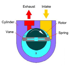
The rotary vane pump is mainly composed of the pump body, rotor, rotary vane, end cover, spring, and so on. A rotor is eccentrically installed in the cavity of the rotary vane pump, the outer circle of the rotor is tangent to the inner surface of the pump cavity (there is a small gap between the two), and two rotary vanes with springs are installed in the rotor slot. When rotating, relying on the centrifugal force and the tension of the spring to keep the top of the rotary vane in contact with the inner wall of the pump chamber, the rotation of the rotor drives the rotary vane to slide along the inner wall of the pump chamber.
The two rotating vanes divide the crescent-shaped space surrounded by the rotor, the pump chamber, and the two end covers into three parts A, B, and C, as shown in the figure. When the rotor rotates in the direction of the arrow, the volume of space A communicating with the suction port increases gradually, and it is in the process of suction. And the volume of space C communicating with the exhaust port is gradually reduced, just in the process of exhausting. The volume of space B in the middle is also gradually decreasing, which is in the process of compression. Since the volume of space A gradually increases (that is, expands), the gas pressure decreases, and the external gas pressure at the inlet of the pump is higher than the pressure in space A, so the gas is inhaled.
When space A is isolated from the suction port, it turns to the position of space B, the gas starts to be compressed, the volume gradually decreases, and finally communicates with the exhaust port. When the compressed gas exceeds the exhaust pressure, the exhaust valve is pushed open by the compressed gas, and the gas passes through the oil layer in the tank and is discharged into the atmosphere. The purpose of continuous pumping is achieved by the continuous operation of the pump.
One stage rotary vane vacuum pump working principle
The single-stage rotary vane pump has only one working chamber, and the pump is mainly composed of a stator, a rotary vane, and a rotor. The rotor is installed eccentrically in the pump chamber, and two rotating vanes are installed in the rotor groove, which is close to the cylinder wall due to the elastic force of the spring (there is also a centrifugal force of the rotating vanes after rotation). The rotor and vanes divide the stator cavity into suction and discharge.
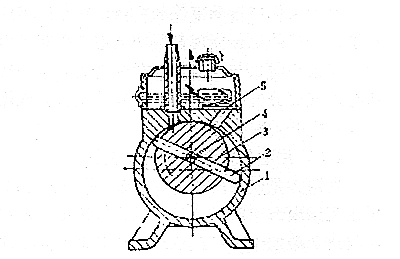
When the rotor rotates in the stator cavity, the volume on the side of the air inlet is gradually expanded periodically to inhale the gas, while the volume on the side of the exhaust port is gradually reduced to compress the inhaled gas and discharge it from the exhaust valve.
The vent valve is immersed in oil to prevent atmospheric air from entering the pump. The vacuum pump oil enters the pump chamber through the oil hole and the exhaust valve so that all the moving surfaces in the pump chamber are covered with oil, forming a seal between the suction chamber and the exhaust chamber.
Two stage rotary vane vacuum pump working principle
In order to improve the ultimate vacuum of the pump, in addition to improving the machining accuracy of the pump body, rotor, and rotary vane, and minimizing the assembly gap and harmful space, the most effective way is to connect two single-stage pumps in series to form a two-stage pump.
The pump consists of two working chambers. The two chambers are connected in series and rotate in the same direction at the same speed. A chamber is the front stage of B chamber. A is the low vacuum stage and B is the high vacuum stage. The pumped gas enters the front stage through the high vacuum stage (B ), and is discharged out of the pump through the exhaust valve. The front stage (A) is the same as the single-stage pump, oil enters the pump chamber at any time, while the high vacuum stage (B) only has a small amount of oil when it starts to work, and no oil enters the pump chamber after working for a period of time. When the pump starts to work and the pressure of the inhaled gas is relatively high (such as starting to pump air from atmospheric pressure), the gas is compressed through the B chamber, and the pressure increases sharply, and a part of the compressed gas is directly discharged from the auxiliary exhaust valve (1) , and the other part is discharged through the front stage.
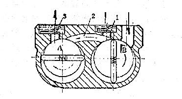
When the pump works for a period of time, when the pressure of the gas inhaled by the B chamber is low, even though it is compressed by the B chamber, the pressure cannot reach above one atmospheric pressure, and the auxiliary exhaust valve 1 cannot be discharged, and all the inhaled gas will enter The front-stage A room is discharged through the exhaust valve 3 through the continuous compression of the A room.
After the pump works for a period of time since the pressure of the high-vacuum stage air intake is greatly reduced, the outlet pressure is also very small, so the pressure difference between the inlet and outlet of the B chamber is also small, and the amount of compressed gas returned is correspondingly reduced; at the same time, the latter stage The oil molecules that are easy to evaporate in the pump are continuously sucked away by the front-stage A chamber, and the partial pressure of the oil vapor is reduced. Therefore, the oil pollution of the two-stage pump is smaller than that of the single-stage pump, and the ultimate vacuum degree will be greatly improved.
1 Stage vs. 2 Stage Rotary Vane Vacuum Pump
1 stage rotary vane pump consists of a single rotor with multiple vanes that rotates within a cylindrical chamber. As the rotor spins, centrifugal force pushes the vanes against the chamber wall, creating a seal and forming variable-volume chambers. The pumping action occurs through the expansion and compression of gas in these chambers, resulting in the generation of a vacuum.
Simplicity: 1-stage pumps have a straightforward design with fewer moving parts, making them compact, lightweight, and easy to operate and maintain.
Cost-Effective: These pumps are typically more affordable compared to 2-stage pumps, making them a cost-effective option for applications that do not require extremely low vacuum levels.
Suitable for Low to Medium Vacuum: 1-stage pumps are ideal for applications that require vacuum levels within the range of approximately 100 to 1,000 mbar (millibar).
Efficient for Low Gas Loads: They perform well when handling low gas loads, making them suitable for applications where gas flow rates are not excessive.
In a 2 stage rotary vane pump, the pumping process is divided into two sequential stages, each with its own set of vanes. The first stage, known as the high-vacuum stage, operates similarly to a 1 stage pump, creating an initial level of vacuum. The gas discharged from the first stage then flows into the second stage, where further compression occurs, resulting in even lower vacuum levels.
Higher Vacuum Levels: 2 stage pumps are capable of achieving significantly higher vacuum levels compared to 1 stage pumps. They can reach vacuum levels as low as 0.1 mbar or even lower.
Improved Gas Handling: These pumps are effective in handling higher gas loads and can efficiently evacuate larger volumes of gas.
Enhanced Backstreaming Resistance: The two-stage configuration provides better resistance to backstreaming, preventing oil or contaminants from reaching the vacuum chamber or system.
Suitable for High Vacuum Applications: 2 stage pumps are well-suited for applications requiring high vacuum levels, such as analytical instruments, vacuum coating, and semiconductor manufacturing.
#rotary vane vacuum pump#two stage rotary vane vacuum pump#rotary vane vacuum pump working principle
0 notes
Text
China offer VALVE CONTROL FLOW G761-3005B for turbine generator
"China offer VALVE CONTROL FLOW G761-3005B for turbine generator
Is YOYIK for the use of turbine units of the power plant supporting professional models of products. YOYIK main generator accessories, generator sets of accessories. For decades, the company relies on advanced technology, technology, materials and scientific management to improve the stability and reliability of the pump, for hundreds of thermal power plants, hydropower stations, cement plants, coal gangue power plants, metallurgical companies, steel and other overhaul , Technical transformation to provide a reasonable and excellent equipment selection, construction planning, installation commissioning, after-sales service, such as perfect complete service, won the power industry industry wide acclaim.
Yoyik can offer many spare parts for power plants as below:
DF-VALVE CONTROL FLOW G761-3005B-DF
Solenoid valve Z2804076
Fluoro Rubber O-Ring OR0311308
sealing ring HB4-56J8-124
high pressure hydraulic pump power pack station 65AY5010 centrifugal pump stainless steel CZ80-250A pump screw HSNH80-27 mechanical rubber seal 10014CH1-5008 transfer pump vane F3V201S8S1C11 globe throttle check valve LJC40C-1.6P dc centrifugal pump 65-250B pump hydraulic power 40AY35X11 vacuum pumps 125LY-35-8 oil transfer electric pump Y160M-2/11KW/IP44 Accumulator bladder LP40 screw pump working ACF090N5ITBP single screw pump HSND280-54 sealing oil Re-Circulating pump HSNH280-43Z dc vane pump F3-V10-1S6S-10-20 three screw pump HSNH440 turbine AC lube pump 125LY-40-B globe throttle check valve KJC25C-4.0P high pressure oil pump 80LY-80-B electric hydraulic oil power pump 80AY506
oil pump cost 50YW25-33
seal sleeve lock nut FK5C32AM-03-02
Manual pressure regulating valve EXCELON B72G-2GK-QD3-RMN
hydraulic pump motor 65AY100
piston pump parts M03EA10VSO45DFR1/31RVPA12
coupling cushion 30-WS
Accumulator NXQ-AB-25-31.5
centrifugal pump types 100-80-125A
Regulating valve KS100ZXNO016 DN100 PN16
vacuum hand pump 125LY-32-B
piston vacuum pump A10VSO100DFR1/32R
vacuum oil pump P-1607
globe valve J1F1.6P-25
VALVE CONTROL FLOW G761-3005B
EH oil pump PV29-2R50C00
screw pump diagram HSND280-43NZ
Vacuum pump 30WS
vacuum pump ac A10VS0100DR/31R-PPA12NOO
radial piston pump hydraulic PVH98QIC-RSF-1S-10-C25-31
gear pump hydraulic 80AY100
pump centrifugal DFB100-80-230
oil pump replacement 80AYP60
mechanical seal for pump 8b1d
reciprocating piston pump PVH074R01AA(AB)10A250000002001AB0
axial piston variable pump PVH98Q1C-RSF-1S-10-C25-31
mechanical face seal BGM37G/50R-G9
reciprocating pump 80AY50*9
mechanical seal for pump BGM37G/50R-G9
RUBBER BLADDER NXQA-25/31.5-L-EH
accumulator NXAQ-10/31.5-L
mian trip solenoid valve 8YVHP trip solenoid valve
turbine OPC solenoid valve HQ16.80Z
rotary vane vacuum pump F3-V10-IS6S-IC-20
rotary vacuum pump P-1761-1
screw pump working principle ACF 090N4 1RBP
Mechanical control valve 224.32.9.1/1X
centrifugal pump DFB80-80-240
butterfly valve K65DSF4PB3
dc screw pump SMH120-42W1Q1
OPC solenoid valve ZD.02.008
dc screw pump HSND280-46
rotary vacuum pump P-1937A
electric transfer oil pump DLZB820-R64A-01
ASTSolenoid valve HQ16.16Z-2
BALL BEARING SINGLE ROW RADIAL DEEP GROOVE NO.6202
Check valve 216C15
liquid ring vacuum pump HSNH660-40NZ
vacuum pump 222v SK-831
electric centrifugal pump head 50-250-007
servo valve J761-002
VALVE CONTROL FLOW G761-3005B
DFYLSYC-2024-7-15-A
"
0 notes
Text
Unveiling the Power of Side Channel Vacuum Pumps
Introduction
In the realm of industrial machinery, side channel vacuum pump stand as stalwart allies, quietly powering numerous critical processes across various sectors. Often overshadowed by their more mainstream counterparts, these pumps possess a unique set of capabilities that warrant closer inspection and appreciation. Join us as we delve into the intricacies of side channel vacuum pumps, uncovering their functionalities, applications, and the distinct advantages they bring to the table.
Understanding Side Channel Vacuum Pumps
Side channel vacuum pumps are dynamic devices engineered to generate vacuum pressure through the centrifugal force produced by the rotation of an impeller. Unlike traditional vacuum pumps that rely on reciprocating or rotary mechanisms, side channel pumps utilize a unique principle known as the side channel effect to achieve superior performance and efficiency.
How Do They Work?
At the heart of a side channel vacuum pump lies an impeller that rotates within a chamber. As the impeller spins, it creates centrifugal force, drawing gas molecules towards the outer edges of the impeller blades. This action compresses the gas and increases its velocity, causing it to exit the pump at a higher pressure than the inlet. The continuous rotation of the impeller results in a steady flow of gas, effectively creating a vacuum within the chamber.
Applications Across Industries
The versatility of side channel vacuum pumps lends itself to a myriad of industrial applications, ranging from manufacturing and packaging to environmental and medical sectors. Some common uses include:
Packaging: Vacuum sealing and packaging of food products to extend shelf life and maintain freshness.
Material Handling: Handling delicate materials such as glass, plastics, and electronic components in production processes.
Printing: Providing suction for paper handling and ink transfer in printing presses.
Medical Equipment: Powering suction devices for surgical procedures, laboratory equipment, and vacuum-assisted wound therapy.
Advantages Over Traditional Vacuum Pumps
Enhanced Efficiency
The unique design of side channel vacuum pumps offers several advantages over traditional vacuum pump technologies. One of the most notable benefits is their inherent efficiency. By leveraging the side channel effect, these pumps can achieve higher compression ratios with lower energy consumption, resulting in significant cost savings over time.
Quiet Operation
Another distinguishing feature of side channel vacuum pumps is their remarkably quiet operation. Unlike noisy reciprocating pumps or cumbersome rotary vane pumps, side channel pumps operate with minimal vibration and noise, making them ideal for noise-sensitive environments such as laboratories and medical facilities.
Compact Design
The compact footprint of side channel vacuum pumps makes them highly versatile and space-efficient. Their streamlined construction allows for easy integration into existing systems without requiring extensive modifications or additional floor space, making them a preferred choice for applications where space is at a premium.
Reliable Performance
Reliability is paramount in industrial settings, where downtime can result in significant losses. Side channel vacuum pumps are renowned for their robust construction and dependable performance, ensuring uninterrupted operation even in demanding environments.
Conclusion
In conclusion, side channel vacuum pumps represent a formidable force in the realm of industrial vacuum technology. Their innovative design, coupled with unmatched efficiency and reliability, makes them indispensable assets across a wide range of applications. Whether in manufacturing, packaging, medical, or environmental sectors, these pumps continue to demonstrate their prowess in delivering consistent vacuum performance. As industries evolve and demand for efficient vacuum solutions grows, side channel vacuum pumps remain poised to meet the challenges of tomorrow with unwavering precision and reliability.
Read More : https://www.becker-international.com/in/1719/side-channel-vacuum-pumps.htm
0 notes
Text
The Ultimate Guide to Rotary Vane Vacuum Pumps: How They Work, Benefits, and Maintenance Tips
Rotary vane pumps are a vital component in various industrial and scientific applications, providing high vacuum pressure for tasks ranging from manufacturing processes to scientific research. In this comprehensive guide, we will delve into the inner workings of rotary vane pumps, explore the numerous benefits they offer, and provide essential maintenance tips to ensure optimal performance and longevity.
I. How Rotary Vane Pumps Work
At the heart of a rotary vane pump lies the ingenious rotary vane principle, which enables the generation of high vacuum pressure. This process involves the use of a rotor with sliding vanes that rotate within a cylinder. As the rotor spins, the centrifugal force pushes the vanes outward, creating a seal against the cylinder wall. This seal divides the pump into multiple chambers, which gradually decrease in volume as the rotor rotates.
When the pump is started, atmospheric pressure pushes air into the largest chamber, known as the inlet chamber, through the intake valve. As the rotor continues to rotate, the volume of the chamber reduces, causing the air to become compressed. As a result, the pressure increases, and the air is forced out through the exhaust valve, leading to the formation of a partial vacuum.
This continuous cycle of intake, compression, and exhaust allows rotary vane pumps to achieve remarkable levels of vacuum pressure, making them ideal for a wide range of applications.
II. Benefits of Rotary Vane Vacuum Pumps
Economy Solutions’ Rotary Vane Vacuum Pumps, in particular, offer numerous advantages that make them a popular choice in various industries.
Reliability and Effectiveness:
One of the key benefits of rotary vane pumps is their reliability. With a well-designed construction and robust components, these pumps can operate continuously for extended periods without any significant drop in performance. Economy Solutions’ Rotary Vane Vacuum Pumps are built to withstand rigorous industrial demands, ensuring consistent and reliable vacuum pressure.
Versatility:
Rotary vane pumps are incredibly versatile, making them suitable for a wide array of applications. Whether it’s in pharmaceutical manufacturing, food processing, or laboratory research, rotary vane pumps can handle a vast range of tasks requiring high vacuum pressure. Their adaptability allows for seamless integration into various systems, making them an indispensable tool in numerous industries.
III. Maintaining Rotary Vane Vacuum Pumps
To maximize the lifespan and efficiency of your rotary vane vacuum pump, regular preventative maintenance is crucial. Here are some essential maintenance tips:
Regular Oil Changes: The oil within the pump plays a vital role in lubricating the vanes, bearings, and other moving parts. Over time, this oil can become contaminated with dust, debris, and moisture, compromising the pump’s performance. Regularly changing the oil, following the manufacturer’s recommendations, is essential to keep the pump running smoothly and efficiently.
Replacing Worn Components: The vanes, bearings, and gaskets in a rotary vane pump are subject to wear and tear over time. Regularly inspecting these components and replacing them when necessary is essential to maintain optimal performance. Worn vanes can cause leaks and reduce the pump’s efficiency, while damaged bearings can result in increased vibration and noise. Additionally, worn gaskets can compromise the seal, leading to a decrease in vacuum pressure.
Contaminated Oil Prevention:
Contaminated oil can cause significant damage to the pump. To minimize the risk of contamination, it is crucial to keep the pump’s environment clean and free from dust and debris. Installing proper filtration systems and regularly checking for any signs of contamination can help mitigate potential issues.
Tips for maximizing the lifespan of rotary vane pumps
Ensure Sufficient Air Flow
One of the primary factors that can significantly impact the lifespan of rotary vane pumps is the availability of adequate air flow. Placing the pump in an area with good air circulation is essential to prevent overheating and potential pump failure. When a pump is surrounded by stagnant air or obstructed by walls or other objects, it can lead to heat buildup, which compromises the pump’s performance and longevity. To achieve sufficient air flow, it is important to position the pump in a well-ventilated area.
Ensure that there is enough space around the pump for air to circulate freely. Avoid placing the pump near walls or other obstructions that may hinder air movement. Regularly inspect the pump’s surroundings and remove any debris or objects that may impede airflow. By ensuring proper air circulation, you can significantly enhance the lifespan of your rotary vane pump.
Minimize Water Vapor Infiltration
Water vapor infiltration can have detrimental effects on the performance and lifespan of rotary vane pumps. When water vapor enters the pump, it can cause operational problems such as corrosion, reduced lubrication, and decreased efficiency. Prolonged exposure to water vapor can lead to severe damage and premature failure of the pump. To minimize water vapor infiltration, it is vital to use proper seals and maintain a dry environment around the pump.
Ensure that all seals are intact and in good condition to prevent any moisture from entering the pump. Regularly inspect and replace seals if necessary. Additionally, it is essential to keep the pump and its surroundings dry. Install dehumidifiers if required, and avoid exposing the pump to excessive moisture or humidity. By taking these preventive measures, you can significantly extend the lifespan of your rotary vane pump.
Explosion Protection
In certain environments, rotary vane pumps may be exposed to explosive atmospheres. It is crucial to be aware of the potential risks associated with such environments and take appropriate safety measures to ensure the pump’s longevity and the safety of personnel.
Explosive atmospheres can result from the presence of flammable gases, vapors, or combustible dust. In these situations, it is essential to consult relevant safety guidelines and regulations specific to your industry. Implement explosion protection measures, such as using explosion-proof pumps or installing appropriate ventilation and monitoring systems. Regularly inspect and maintain these safety measures to ensure their effectiveness.
Use of PFPE Operating Fluids
Another way to maximize the lifespan of rotary vane pumps is by using perfluoropolyether (PFPE) operating fluids. These fluids offer several benefits that contribute to the pump’s longevity and performance. PFPE fluids have excellent lubrication properties, reducing friction and wear within the pump. This results in less stress on the pump’s components and extends their lifespan.
Additionally, PFPE fluids are highly resistant to chemicals, making them suitable for a wide range of applications. They provide excellent stability and prevent the formation of harmful by-products that can damage the pump. By using PFPE operating fluids, you can ensure optimal lubrication and protection for your rotary vane pump, enhancing its lifespan and overall performance.
In conclusion, rotary vane pumps play an indispensable role in a myriad of industrial and scientific applications due to their reliability, versatility, and efficiency.
At Economy Solutions, the design and robustness of these pumps are tailored to meet rigorous demands, ensuring top-notch performance across various sectors. Proper maintenance, from regular oil changes to the prevention of water vapor infiltration, remains pivotal to the pump’s longevity.
By understanding the importance of adequate air flow, explosion protection, and the use of high-quality PFPE operating fluids, users can significantly enhance the lifespan and operational efficiency of their rotary vane pumps. As we navigate the complexities of industrial processes, the rotary vane pumps from Economy Solutions stand out as a beacon of durability and efficiency.
To know more: https://www.economysolutions.in/the-ultimate-guide-to-rotary-vane-vacuum-pumps-how-they-work-benefits-and-maintenance-tips/

0 notes
Text
Exploring the Role of Vacuum Pumps in Helium Leak Testing

In today's highly competitive industrial landscape, precision and quality are non-negotiable. Manufacturers across various sectors, from aerospace to electronics, rely on cutting-edge technology to ensure that their products meet stringent standards. One critical technology that has gained prominence in ensuring quality and leak detection is helium leak testing. At the core of this methodology, vacuum pumps play a pivotal role in creating the necessary conditions for the accurate detection of even the tiniest leaks. In this blog, we will delve into the essential role of vacuum pumps in helium leak testing, with a particular focus on dry screw vacuum pumps. We will also explore the contributions of vacuum furnaces, helium recovery systems, and the importance of helium leak testing services, all while keeping an eye on the key players in the industry, including rotary vane vacuum pump manufacturers.
The Role of Vacuum Pumps in Helium Leak Testing
Helium leak testing is a highly effective method for identifying leaks in various components and systems. It relies on the use of helium gas as a tracer, which can penetrate the smallest of openings, making it a powerful tool for pinpointing leaks that might go undetected by other methods. However, the success of helium leak testing is heavily dependent on the ability to create a vacuum within the testing chamber. This is where vacuum pumps come into play.
Dry Screw Vacuum Pumps: The Unsung Heroes
Dry screw vacuum pumps are a popular choice for creating the necessary vacuum conditions in helium leak testing. These pumps are engineered to be highly efficient and reliable, making them well-suited for the demanding requirements of leak detection processes. Their working principle involves the use of two screw rotors that rotate to create a vacuum by trapping and transporting gas molecules. They are oil-free and provide consistent performance, making them the preferred choice for applications where product purity is essential.
One of the key advantages of dry screw vacuum pump is their low maintenance requirements. They are designed to operate continuously with minimal service interruptions, reducing downtime and ensuring the reliability of helium leak testing processes. Moreover, their quiet operation and energy efficiency make them a top choice for various industries where noise control and cost-effectiveness are priorities.
Vacuum Furnaces: Where Precision Meets Quality
In the context of helium leak testing, vacuum furnaces play a crucial role in preparing the test specimens for accurate and reliable results. The purpose of using vacuum furnaces in this process is twofold: to outgas the test specimen and to create an environment free of impurities.
Outgassing involves heating the specimen in the vacuum furnace to remove any volatile materials or contaminants that could interfere with the helium leak testing. This step is essential to ensure the accuracy of the test, as any outgassing during the test can lead to false positives or negatives.
Additionally, vacuum furnaces create a clean environment, which is vital for helium leak testing. Any impurities in the testing chamber can alter the results and lead to inaccurate readings. Vacuum furnaces provide the controlled, pristine environment necessary for a successful helium leak test.
Helium Recovery Systems: Reducing Costs and Environmental Impact
Helium is a valuable and finite resource, and its use in leak testing can be costly. To address this issue, helium recovery system have become an integral part of helium leak testing processes. These systems capture and recycle helium used during testing, reducing both costs and the environmental impact of helium consumption.
Helium recovery systems work by collecting the helium gas after it has been used in the test chamber, purifying it, and then storing it for future use. This not only saves money but also ensures a sustainable approach to helium usage, which is especially important given the global helium shortage.
The Importance of Helium Leak Testing Services
While the technology and equipment used in helium leak testing are essential, the expertise of professionals providing helium leak testing service cannot be overlooked. These services often combine the use of advanced equipment, including dry screw vacuum pumps and vacuum furnaces, with the skills and experience of trained technicians.
Helium leak testing services offer several advantages, including:
Expertise: Trained technicians understand the intricacies of helium leak testing, ensuring accurate results and effective problem-solving.
Customization: Helium leak testing service can be tailored to specific requirements, making them suitable for a wide range of industries and applications.
Efficiency: Helium leak testing services can be more efficient than in-house testing, saving time and resources for manufacturers.
Quality Assurance: Professional services help maintain the highest quality standards in leak detection.
Rotary Vane Vacuum Pump Manufacturers: Leading the Way
Rotary vane vacuum pumps, though not as prevalent in helium leak testing as dry screw vacuum pumps, remain a vital component in the vacuum technology landscape. These pumps operate using a rotor with vanes that spin inside a cavity, creating the necessary vacuum for various applications, including helium leak testing.
Rotary vane vacuum pump manufacturers play a significant role in shaping the industry by designing and producing reliable, high-performance vacuum pumps. Their innovations and continuous improvement in vacuum pump technology contribute to the success of helium leak testing processes across different sectors.
Helium leak testing has become an indispensable tool in ensuring the quality and safety of products in industries ranging from aerospace to electronics. At the heart of this technology are vacuum pumps, with dry screw vacuum pumps leading the way, alongside vacuum furnaces, helium recovery systems, and helium leak testing services. The precision, reliability, and efficiency of these elements are critical in achieving accurate and consistent results.
In addition, the contributions of rotary vane vacuum pump manufacturers in advancing vacuum technology highlight the collaborative nature of the industry. As manufacturers continue to push the boundaries of technology, helium leak testing will remain a cornerstone in quality control and product development, helping industries deliver excellence to their customers while conserving precious helium resources and reducing environmental impact.
0 notes
Text
An Introduction to Mechanical Booster Vacuum Pumps
What is a Mechanical Booster Vacuum Pump?
Imagine you are tasked with designing a high-quality vacuum system for a chemical processing plant or a pharmaceutical manufacturing facility. You need a vacuum pump that is efficient, reliable, and capable of achieving the desired vacuum levels for your specific process requirements. Enter the mechanical booster vacuum pump, a versatile and powerful tool that can help you achieve your goals!
A mechanical booster vacuum pump, also known as a Roots pump, is a type of positive displacement pump that can be used to increase the vacuum level in a system. It is designed to operate in conjunction with a primary pump, typically a rotary vane or rotary piston pump, to improve the overall performance and efficiency of the vacuum system. The mechanical booster pump is an essential component in many industrial processes, offering numerous advantages and benefits over other types of vacuum pumps.
In this blog post, we will take an in-depth look at mechanical booster vacuum pumps, exploring their working principle, advantages, and typical applications in various industries. By the end of this article, you will have a better understanding of why mechanical booster vacuum pumps are a valuable tool for process engineers and how they can help optimize your vacuum system.
How Does a Mechanical Booster Vacuum Pump Work?
The mechanical booster vacuum pump operates on the principle of positive displacement, which involves trapping a fixed volume of gas and then expelling it from the pump. The pump consists of two counter-rotating lobes, or rotors, that are synchronized by a pair of gears. As the rotors turn, they create a series of expanding and contracting volumes between the rotors and the pump casing. This action draws gas into the pump, compresses it, and expels it through the exhaust.
Since the mechanical booster pump does not compress the gas internally, it relies on a primary pump to reduce the gas pressure before it enters the booster. This allows the mechanical booster pump to operate more efficiently, as the gas is already at a lower pressure when it reaches the booster stage. The combination of the primary pump and mechanical booster pump results in a more effective and powerful vacuum system, capable of achieving deeper vacuum levels and higher pumping speeds than a primary pump alone.
It is important to note that mechanical booster vacuum pumps are not designed to operate at atmospheric pressure. In fact, they can suffer severe damage if they are operated in this manner. To prevent this, a bypass valve was often installed to protect the pump from overpressure, allowing it to operate within its optimal pressure range but with variable frequency drives getting economical, Vacuum Booster motors are nowadays provided with variable frequency drives.
What are the Advantages of Using a Mechanical Booster Vacuum Pump?
There are several key advantages to using a mechanical booster vacuum pump in your vacuum system, including:
Increased pumping speed: By augmenting the performance of the primary pump, a mechanical booster pump can significantly increase the pumping speed of a vacuum system. This means that the system can achieve the desired vacuum level more quickly and efficiently, saving time and energy.
Improved vacuum level: Mechanical booster vacuum pumps can help achieve deeper vacuum levels than a primary pump alone. This is particularly beneficial in applications where a high vacuum level is required for optimum process performance.
Energy efficiency: Due to their design and mode of operation, mechanical booster vacuum pumps are more energy-efficient than other types of vacuum pumps. This translates to lower operating costs and a reduced environmental impact.
What are Some Typical Applications for Mechanical Booster Vacuum Pumps?
Mechanical booster vacuum pumps are used in a wide range of industries and applications, including:
Chemical processing: In chemical processing plants, mechanical booster vacuum pumps are used to optimize the vacuum levels for various processes, such as distillation, evaporation, and drying. This ensures that the products are of high quality and that the processes are as efficient as possible.
Pharmaceutical manufacturing: In the pharmaceutical industry, mechanical booster vacuum pumps are used to maintain the required vacuum levels for processes such as freeze-drying, degassing, and sterilization. This helps to ensure that the final products are safe, effective, and of the highest quality.
Vacuum furnaces: Mechanical booster vacuum pumps are used in vacuum furnaces to achieve the desired vacuum levels for various heat treatment processes, such as brazing, sintering, and annealing. This helps to improve the quality and performance of the treated materials.
In conclusion, mechanical booster vacuum pumps are an indispensable tool for process engineers in various industries. Their ability to increase pumping speed, achieve deeper vacuum levels, and operate efficiently makes them an ideal solution for optimizing vacuum systems in chemical processing, pharmaceutical manufacturing, vacuum furnaces, and more.
If you are considering incorporating a mechanical booster vacuum pump into your vacuum system, consult with our team of experts. We can help you determine the best pump configuration for your specific process requirements and provide guidance on how to optimize your vacuum system for maximum performance and efficiency.
Contact us today to learn more about our mechanical booster vacuum pumps and how they can benefit your processes!
Contact Us: Economy Process Solutions Private Ltd
Email: [email protected]
(IN) - +91 22 2520 5864
1 note
·
View note
Text
How Does A Two Stage Rotary Vane Vacuum Pump Work?
How Does A Two Stage Rotary Vane Vacuum Pump Work?
A two-stage rotary vane vacuum pump is a powerful device used to create and maintain a vacuum in various applications, such as laboratories, industrial processes, and scientific research. This type of pump operates on a relatively simple yet efficient principle, making it widely utilized in a range of industries. In this passage, we will explore how a two-stage rotary vane vacuum pump works, its components, and the processes involved in generating a vacuum.Get more news about Two Stage Rotary Vane Vacuum Pump Seller,you can vist our website!
At its core, a two-stage rotary vane vacuum pump consists of two stages, each comprising a cylindrical housing with a rotor positioned eccentrically inside. The rotor is equipped with several vanes that are free to move in and out of radial slots along its length. These vanes are typically made of carbon or other self-lubricating materials and play a vital role in the functioning of the pump.
The pumping process begins when the pump is connected to the system or chamber that requires a vacuum. Initially, both stages of the pump are filled with air at atmospheric pressure. As the pump is activated, an electric motor drives the rotation of the rotor inside each stage. The rotor's eccentric position causes the vanes to slide in and out of their respective slots, creating variable chambers within the pump housing.
In the first stage, the rotation of the rotor causes the vanes to move outward due to centrifugal force. As a result, the volume of the chamber between the rotor and the housing increases. This expansion creates a partial vacuum within the chamber, causing the gas molecules inside the system or chamber to move towards the pump inlet. The gas molecules are then trapped between the vanes and the chamber wall, preventing their escape back into the system.
As the rotor continues to rotate, the vanes sweep the gas towards the pump's exhaust port. The shape of the pump housing guides the gas towards the exhaust, which is typically fitted with a valve to prevent backflow. This expulsion of gas from the first stage creates a lower pressure region in the system or chamber, facilitating the movement of gas from the higher-pressure region towards the pump.
After passing through the first stage, the gas enters the second stage of the rotary vane vacuum pump. The operation of the second stage is similar to that of the first stage. The rotation of the rotor and the movement of the vanes create a vacuum in the chamber, causing gas molecules to be drawn into the pump and trapped between the vanes. This stage further compresses the gas, reducing its volume and increasing the pressure difference between the system or chamber and the pump.
Once the gas reaches the second stage's exhaust port, it is expelled from the pump, further lowering the pressure within the system or chamber. By utilizing two stages, the pump can achieve higher levels of vacuum compared to single-stage pumps. The compression ratio, which is the ratio of the discharge pressure to the inlet pressure, is significantly improved due to the additional compression in the second stage.
To ensure the smooth operation and longevity of the pump, proper lubrication is essential. Rotary vane vacuum pumps are equipped with an oil reservoir that lubricates the vanes, reduces friction, and maintains a tight seal between the vanes and the pump housing. The oil also acts as a sealant, preventing air from entering the pump and reducing internal leakage.
However, the presence of oil in the pump also requires the inclusion of an oil management system. This system separates the oil from the discharged gas, either through oil separators or oil mist filters. The separated oil is then collected and recirculated back into the pump, while the gas is released into the atmosphere or subjected to further treatment, depending on the specific application and requirements.
In summary, a two-stage rotary vane vacuum pump operates by using rotating vanes to create chambers with expanding and contracting volumes. This process allows the pump to draw gas molecules from a system or chamber, compressing and expelling them to create a vacuum. With its reliable and efficient design, the two-stage rotary vane vacuum pump has become an indispensable tool for a wide range of vacuum applications, ensuring the smooth operation of various industries and scientific endeavors.
0 notes
Text
Closed loop system of liquid ring vacuum pump
It is different from single-stage and double-stage vacuum pumps. It is a single-stage vacuum pump and a double-stage vacuum pump.
1. Separator pressure gauge: if pressure may be generated in the separator, a pressure gauge shall be installed on the separator;
2. Suction port vacuum check valve: in order to prevent backflow when the vacuum pump / compressor is shut down, it is generally necessary to install a vacuum check valve or pneumatic valve at the inlet of the pump;
3. Working fluid booster pump: if the working fluid supply of the pump is insufficient or the working pipeline resistance is large, the working fluid booster pump can be installed;
4. Air port filter: if foreign matters may enter the pump in the system and pipeline, a filter or filter screen shall be installed at the suction port of the pump;
5. Cavitation protection pipeline: if the suction pressure of the vacuum pump is close to the saturated vapor pressure of the working fluid, a cavitation protection pipeline should be installed between the vacuum pump and the separator;
6. Exhaust condenser: if it is necessary to capture or recover the condensable gas at the exhaust port, a condenser can be installed at the exhaust port of the gas-liquid separator;
7. Liquid replenishing port of separator: if the working fluid is insufficient, the working fluid can be replenished properly from the liquid replenishing port;
8. If the vacuum pump has other special requirements, the corresponding accessories can be installed.
Rotary Vane Vacuum Pump Working Principle
Rotary Vane Vacuum Pump
Dry Scroll Vacuum Pump
0 notes
Text
Different Types of Vacuum Pumps and also Solutions
Air pump as well as systems are necessary for preserving the appropriate degree of stress in a system. They are used in many applications in several settings, from the house to huge commercial complicateds. Because fluids can not be pulled, suction can not be used to produce a vacuum cleaner. Therefore it ends up being needed to create an artificial vacuum cleaner, and the easiest manner in which this can be completed is by increasing the air that is in a container. In order to leave a chamber continuously, these makers have a compartment that is constantly being shut off, cleared, and also them increased once more. This is the principle whereby these makers work.
Self priming trash pump
Busch air pump and also systems are now readily available in several sizes and shapes. You will find that they operate the same fundamental principles, however the larger ones for commercial demands are much more complex. The following is a short checklist of the different types that have been developed until now:
Engine Driven Water Pump
o Rotary vane - without a doubt the most generally utilized
o Diaphragm - no contamination from oil
o Liquid ring
o Piston - the most affordable cost
o Scroll - includes the greatest speed for a completely dry pump
o External Vane
o Roots Blower - likewise known as a booster; it has a high pumping price, however reduced compression
o Multistage origins - utilizes a number of phases to create both broadband and also compression
Kinney air pump and also systems also make use of numerous different sorts of techniques in order to accomplish their function. Many times this involves making use of multiple chambers, pumps, and also procedures. As an example, favorable displacement pumps can produce just small vacuums because of mechanical limitations. These stronger vacuum cleaners have to be created utilizing an extra complex collection of phases typically beginning with a quick pump down. There are many different kinds of mixes that can be utilized in order to attain the wanted results.
So, since you recognize a bit extra regarding exactly how these Edwards vacuum pumps and systems job, it is time to talk about a few of the scenarios where they can be utilized. There are several markets as well as makes use of for these devices, including, yet not restricted to the following: composite plastic molding, flight tools in aircraft, the manufacturing of electrical lights as well as CRTs, processing of semiconductors, electron microscopy, vacuum cleaner finishing, freeze drying, garbage compacting, sewage treatment, as well as much more.
This write-up consists of just a couple of instances of the several various options you have when it pertains to vacuum pumps and also systems. When searching for the ideal one for your application, it is a great idea to utilize the sort of product that is advised by the maker or your equipment. While there are business that deal in these items all over the globe, you will certainly obtain the best service when you choose a person near to you.
1 note
·
View note
Text
Kinds of Peripheral Flow Sends and Their Doing work Mechanism
Kinds of Peripheral Flow Sends and Their Doing work Mechanism
A Peripheral Flow Pump can be a device that works well for the flow regarding fluids. The mechanism of your pump works simply by recirculating fluids numerous times. The pump can also be used to create large pressure plus head. This mechanism is quite useful in many applications. Here are some plus the the pump's characteristics. Let's discuss the sorts of peripheral flow pumps and their being employed mechanism.
The efficiency on the pump can always be determined from their characteristic curve. In general, the efficiency contour is plotted while H = f (Q). Flow rate is add up to 0 when the head is at its highest. Flow rate as well as head increase throughout direct proportion to each other. This relationship is also applicable to the electricity input and output with the pump. These Peripheral Flow Pump Manufacturer curves differ for various kinds of pumps. These differences within the curves are from the different design and efficiency options that come with the pumps.
Essentially the most common form connected with rotary pump is a gear pump. It comprises of two meshed equipment that rotate from a casing. The areas between the items teeth trap along with push the fluid, creating centrifugal induce. Unlike the scooping actions, fluid doesn't return to the meshed part. Gear pumps are utilized in different hydraulic power packs and motor vehicle engine oil pumps. A gear pump's doing work principle is a bit like a car tyre.
A circumferential flow pump includes a rotor with some sort of plurality of circumferential flow impellers mounted on the rotor. YOUR stator surrounds the particular rotor. It also offers a centrifugal magnetic generator coupled to it. Once these two pumps interact to move liquid, they will discharge it over the suction port. The next seal means THIRTY-ONE and third close off means 32 are disposed in the housing between the rotor as well as the pump stages.
The other type of peripheral flow pump is often a rotary impeller. It involves multiple radial vanes that are aligned along its periphery. The impeller rotates together with increasing pressure within the casing channel. The fluid included in the pump is more affordable than the substance outside the pump motor. A spiral path is formed over the perimeter of the pump the location where the vortices meet. The greater vortices there are, the greater this pressure.
The great things about peripheral pumps are make can generate a top pressure even should the flow is very low. Since the impeller turns close to the pump's volute, the actual difference in demand between the source and output is substantial. Peripheral pumps are less costly than centrifugal pumps and possess a higher self-priming potential. These features make them a good choice for you are able to. There are advantages to choosing this type of pump.
Unlike displacement penis pumps, a peripheral knock out is characterized with a smaller size. Their small size makes for smaller measurements for any same output. They're also suited to pure, non-abrasive essential fluids. They can be used in several different pumping applications, as well as pressure-boosting, car-wash, along with chemical industries. The only downside to using this pump type is always that it's less powerful than its displacement knock out cousin.
A turbo hoover pump is another example on the peripheral flow pump motor. Its turbo-vacuum pump motor reduces the pushed force generated because of the discharged gas. It is equally capable of working together with corrosive fluids. It also has the benefit of being easy to keep up. In addition, it's simple to control. And, as a result, it's an outstanding choice for applications that require a high level associated with efficiency.
A turbo void pump comprises a housing, rotor, in addition to discharge port. The rotor compresses and discharges gas. The motor devices the pump over the discharge port and a second purge gasoline supply port. The pump is supported by bearing means at the axial ends. The current invention can defeat these problems, and was designed to be simple and inexpensive. It also provides high-speed functioning. This type involving pump can operate at high pressure and can be manufactured at less costly.
1 note
·
View note
Text
Yoyik supply valve R901339109 for power plant
Yoyik can offer many spare parts for power plants as below:
DF-valve R901339109-DF
multistage centrifugal pumps 65-250B
electric oil transfer pump 3GW45X4-46
Steel pipe flange metal gasket HG/T20612-2009
Check valve A2969 1""
magnetic coupling centrifugal pump ISG150-160
high pressure centrifugal pump IHF80-50-200
electric motor with hydraulic pump 50YW32-200
hydraulic piston pump spare parts 16G2AT-HMP(DN25)*1600DKOL-28-DN25
rotary piston pump PVH098R01AJ30A250000002001AB010A
bellows globe valve WJ40F1.6-II DN40
axial piston variable pump PVH098R01AAD30A250000002001AB010A
mechanical seal FA1D56
Electric gate valve Z941Y-40 PN4.0MPA DM500
hydraulic pump spare parts 70LY-34
SEALING RING 2BE1 353 OZY4Z
metering piston pump PVH098B01AJ30A250000001001AB010
Gate valve Z41H-25
Adjustment valve ZKFKP-250-65-14
multi stage centrifugal pump 65-250B
Accumulator blader plus seal NXQ-AB 80/31.5-L-Y
Gear pump GPA3-63-E-20-R6.3
multi stage centrifugal pump DF-DFB100-8
globe throttle check valve LJC80-4.0P
coupling flexible shaft ACF090N5ITBP
hydraulic pump piston 2.5CY14-1B
Mechanical seal BKM(FX)103055
piston pump parts A10VS0100DRS/32R-VPB12N00MNR
transfer pump vane F320V12A1C22R
rotary vacuum pump P-1751
pressure hose SMS-10/20-1829mm-C
oil transfer electric pump 50AY60
hydraulic screw pump KF80NZ/4.0F6
coupling 125LY-23
switch valve M765-004000A
Tooth belt SA-22A 3VX560
Accumulator NXQ-A-2.5/31.5-L
valve R901339109
Cartridge valve GS060600V
Mechanical seal ZU44-45
Low pressure oil pump SDV10-1P7P
sealing ring HB4-56J8-100
globe throttle check valve LJC40-4.0P
dc screw pump NM076SY03S18B
EH oil pump shaftoil seal TCM-589332
globe throttle check valve LJC100C-4.0P
DDV valve D634-327C
non-return valve DY25.PC268-DF
Regulating valve 0508.1475T1601.AW025
piston hydraulic pump A3H37-FR01KK-10
AC lube pump impeller nut 125LY-35
seal sleeve lock nut FK5C32AM-03-02
PROFILE SEAL 564/550X17.11
differential pressure valve 514D090-05
globe throttle check valve LJC100-2.5P
differential pressure valvediaphragm 977HP
accumulator bladder NXQAB-10/31.5-2-A
twin screw pump HSN210-54
centrifugal pump parts DFB-80-80-240
lubricant oil cooler sealing strip N35-MGS-16C/2
Fluoro Rubber O-Ring OR0020013
mechanical seal pdf 108-45
metering piston pump PV29-2R5D-C00
multi stage centrifugal pump DFB100-65-260
pump screw HSNH210-54
metering piston pump PVH74RO1A-RSM-1S-10-C25-3
high pressure piston pump A3H56-FI01KK-10
metering piston pump 2.5CY14-1B
vacuum pump compressor P-2402
pumps centrifugal 50-250-007
mannual bellows globe valve 40FWJ1.6P
screw pump working principle ACG045N6IVBP
solenoid relief valve DBW32B-2-5X/100U6AW230-50N9K4
safety valve 3.5A25F-16P
valve R901339109
DFYLSYC-2024-7-8-A
"
0 notes
Text
27 basic knowledge points of centrifugal pump!
1. What is the main working principle of centrifugal pump?
The motor drives the impeller to rotate at a high speed, causing the liquid to generate centrifugal force. Due to the action of centrifugal force, the liquid is thrown into the side channel and discharged out of the pump, or into the next stage impeller, so as to reduce the pressure at the inlet of the impeller and form a pressure difference with the pressure acting on the suction liquid. The pressure difference acts in the liquid suction pump. Due to the continuous rotation of the centrifugal pump, The liquid is continuously inhaled or discharged.
2. What are the functions of lubricating oil (grease)?
Lubrication, cooling, flushing, sealing, vibration reduction, protection and unloading.
3. What is the three-stage filtration of lubricating oil before use?
Level I: between the original lubricating oil barrel and the fixed barrel;
The second stage: fixed between the oil barrel and the oil pot;
Level 3: between the oil pot and the refueling point.
4. What is the "five determinations" of equipment lubrication?
Fixed point: add oil at the specified point;
Timing: oil the lubricating parts according to the specified time and change the oil regularly;
Quantitative: quantitative refueling according to consumption;
Quality determination: select different lubricating oils according to different models and keep the oil quality qualified;
Fixed person: each refueling part must be in the charge of a special person.
5. What is the harm of water in pump lubricating oil?
Water can reduce the viscosity of lubricating oil, weaken the strength of oil film and reduce the lubrication effect.
Water below 0 ℃ will freeze, which will seriously affect the low-temperature fluidity of lubricating oil.
Water can accelerate the oxidation of lubricating oil and promote the corrosion of low molecular organic acids to metals.
Water will increase the foaming property of lubricating oil and make the lubricant easy to generate foam.
Moisture can rust metal parts.
6. What are the maintenance contents of the pump?
Carefully implement the post responsibility system, equipment maintenance and other rules and regulations.
The equipment lubrication shall be "five fixed" and "three-level filtration", and the lubrication equipment shall be complete and clean.
Maintenance tools, safety facilities, fire-fighting equipment, etc. shall be complete and placed neatly.
High temperature in two-stage rotary vane vacuum pump?
0 notes
Text
Unveiling the Versatility and Efficiency of Oil Sealed Rotary Piston Pump
Oil Sealed Rotary Piston Pump have long been recognized as a reliable and versatile technology in various industries, including manufacturing, automotive, aerospace, and research. These pumps excel in creating vacuum or pressure environments, enabling the smooth operation of countless processes. In this blog post, we will delve into the intricacies of oil sealed rotary piston pumps, exploring their working principle, applications, advantages, and limitations. By the end, you will have a comprehensive understanding of this remarkable pump and its significant contributions to diverse sectors.

I. Working Principle : The oil sealed rotary piston pump operates on a relatively simple yet effective principle. It consists of a cylindrical pump chamber housing an eccentrically mounted rotor with several vanes. The rotor is driven by a motor, and as it rotates, the vanes slide in and out of the rotor slots, maintaining contact with the inner surface of the pump chamber. A constant supply of oil fills the chamber, serving multiple purposes in the pump’s operation.
During the rotation, the vanes trap gas molecules between the rotor and the pump chamber. As the rotor continues to rotate, the trapped gas is compressed, leading to an increase in pressure. Simultaneously, the oil within the chamber forms a seal, preventing gas leakage and maintaining the pump’s efficiency.
II. Applications : Oil sealed rotary piston pumps find extensive application across various industries. Here are some notable examples:
Vacuum Technology: These pumps play a crucial role in creating and maintaining vacuum conditions essential for numerous processes. They are used in vacuum packaging, freeze drying, vacuum distillation, and semiconductor manufacturing, among others.
Chemical and Pharmaceutical Industries: Oil sealed rotary piston pumps are utilized in chemical and pharmaceutical processes for handling volatile or corrosive gases. They are employed in filtration, solvent recovery, evaporation, and reactor charging.
Research and Development: In research laboratories, these pumps are employed for experiments requiring vacuum or controlled gas environments. Applications include material testing, mass spectrometry, electron microscopy, and thin film deposition.
Automotive Sector: Oil sealed rotary piston pumps are integral components in automotive applications, particularly for braking systems. They create vacuum conditions required for power-assisted braking, ensuring optimal vehicle safety.
Power Generation: The pumps are used in power plants for condenser air extraction, steam turbine sealing, and maintaining vacuum conditions in steam turbine condensers.

III. Advantages : Oil sealed rotary piston pumps offer several advantages that make them highly sought after in various industries:
Versatility: These pumps can operate in a wide range of pressure and vacuum levels, making them suitable for diverse applications. They can handle both clean and contaminated gases efficiently.
High Reliability: Oil sealed rotary piston pumps are known for their durability and robustness. They have a long lifespan and require minimal maintenance, reducing downtime and operational costs.
Continuous Operation: These pumps are capable of continuous operation without overheating or performance degradation, ensuring uninterrupted processes.
High Efficiency: The oil seal mechanism in these pumps provides excellent sealing properties, minimizing gas leakage and enhancing pumping efficiency.
Cost-Effectiveness: Oil sealed rotary piston pumps offer a favorable cost-to-performance ratio. Their initial investment cost is relatively lower compared to other vacuum technologies, making them an economical choice.
IV. Limitations : While oil sealed rotary piston pumps possess numerous advantages, it is important to consider their limitations as well:
Oil Contamination: The oil used for sealing and lubrication can become contaminated over time, particularly when handling reactive or corrosive gases. Regular oil changes and maintenance are necessary to prevent pump performance deterioration.
Noise and Vibration: These pumps can generate considerable noise and vibration during operation, which may require additional measures to mitigate their effects.
Environmental Impact: The oil used in these pumps requires proper disposal, as it can be hazardous to the environment. Careful handling and adherence to disposal regulations are essential.
Limited Vacuum Levels: Oil sealed rotary piston pumps are not suitable for achieving ultra-high vacuum conditions. For applications requiring extremely low pressures, alternative pump technologies may be more appropriate.

Conclusion : Oil Sealed Rotary Piston Pump are indispensable devices in a wide range of industries, providing reliable vacuum and pressure environments for various processes. Their versatility, efficiency, and cost-effectiveness have made them a preferred choice for numerous applications. By understanding the working principle, applications, advantages, and limitations of these pumps, industries can harness their capabilities effectively, ensuring optimal performance and productivity. As technology continues to evolve, it will be fascinating to witness the further advancements and refinements of oil sealed rotary piston pump designs in the years to come. Tekman India is one of the best manufacturer and supplier of premium quality range of Rotary Vane Vacuum pumps and Single Stage Vane Pump across India.
0 notes
Text
How Liquid Ring Pump Works And Its Uses

Across various industries, vacuum pumps are used for endless applications, from removing moisture from products to packaging all sorts of consumer goods. From industrial plants to medical laboratories, there is no doubt about the capabilities of this machine in fulfilling demands. One particular type of this machine is worth highlighting in this article - the liquid ring pump.
The Design of Liquid Ring Pump
Liquid ring pumps come in single and multistage variations that work through a positive-displacement pumping principle. It works similarly to its rotary vane counterpart. In general, its overall design is low friction and the only component that moves is the rotor. In many cases, the pump is powered by induction motors. In some circumstances, the liquid ring is removed from the gas via external elements in which it is cooled prior to sending it back to the pump’s casing.
With its inherent design, the liquid ring pump can handle heavy and rugged industrial applications involving wet environments. It works around a rotating impeller that is free of fiction. The ambient air is being sucked into the pump which will then be compressed with the liquid and be discharged. There are plenty of chambers that are created by the impeller, hence the gas is expelled continuously during each rotation.
The Application of Liquid Ring Pump
The liquid ring pump is used across a range of industrial applications. From producing paper to refining petroleum, the pump is found to be so useful. It is also very commonly applied in steam-turbine generators to suck gas. Likewise, it is utilized to remove water from pulp slurries and press felts to produce all kinds of paper. In addition, the pump is also useful in drawing groundwater from deep wells for soil remediation purposes.
Ultimately, liquid ring pumps have long been considered as the most ideal pumping technology that can process extreme vapour loads. This includes the processes involving evaporation, distillation, and similar tasks where both dry and wet gases have to be dealt with.
A liquid ring vacuum will accept any liquid with the right vapor pressure qualities. In most applications, water is used as the sealant, with oil being a distant second. Therefore, liquid ring vacuums that are oil-sealed generally need to be cooled with air.
The liquid ring pump has long been established as the most ideal pump for handling extreme vapor loads. In processes that involve distillation, evaporation and other condensable tasks, liquid ring vacuums are the best technology for handling wet as well as dry gases that carry liquid. McRae Engineering sells liquid ring pumps in both single and dual-stage designs, which makes the technology applicable for a whole host of industrial demands.
0 notes
Text
Positive Displacement Blower Repair USA
Positive Displacement blowers use mechanical power to squeeze fluid and thereby increase the pressure. Rotary Vane and Rotary Lobe are the two types of positive displacement blowers, Positive displacement blowers are often driven by direct-coupled electric motors but they can also be driven by gas engines, hydraulic motors, etc in unusual circumstances. Positive displacement blowers are used in pneumatic conveying, for sewage aeration, filter flushing, gas boosting, as well as to move gases of all kinds in the petrochemical industries.
Blowers are specified on the basis of pressure and flow rate. Blowers can be purchased based on the ratio of system inlet pressure and outlet pressure. Some of the important points to be considered while selecting blowers are the structure of blades, the flow capacity, the port design, and more.
Centrifugal blowers resemble centrifugal fans. Multi-stage centrifugal blowers are used to generate greater pressures. In positive displacement industrial blowers, a fixed amount is entrapped and sent forward with greater pressure. They are beneficial to application processes that are prone to clogging. Industrial blower efficiency is the ratio between the power transferred to the air stream and the power delivered by the motor to the blower. The efficiency of the blower depends upon the type of impeller being used.
Vacuum Pumps are an integral part of industrial manufacturing processes which includes packaging, bottling, drying, degassing, pick and place, to name a few. For smooth and efficient working of any system, pumps are required, and hence it is crucial to understand the features, benefits, and operating principles of vacuum pump technology.
We are a dedicated team to ensure the highest quality of blower renewal. We can offer anywhere from complete overhauls or a simple bearing change. Our full service machine shop assists our team to rebuild your units to original factory specification on a wide range of blowers. Our certified technicians are positioned to give you the best quality renewal, in some cases exceeding OEM rated life capacity by upgrading crucial components in your units. If you have a centrifugal blower, positive displacement and exhausters we can assist you to get your unit back in service.
We are based in Houston, Texas and our skilled technicians will address all your queries.
Web:http://americanblowerllc.com/

0 notes
Text
Useful information on External Gear Pumps
A gear pump is a type of positive displacement (PD) pump. Gear pumps use the actions of rotating cogs or gears to transfer fluids. The rotating gears develop a liquid seal with the pump casing and create a vacuum at the pump inlet. Fluid, drawn into the pump, is enclosed within the cavities of the rotating gears and transferred to the discharge. A gear pump delivers a smooth pulse-free flow proportional to the rotational speed of its gears.
There are two basic designs of gear pump: internal and external (Figure 1). An internal gear pump has two interlocking gears of different sizes with one rotating inside the other. An external gear pump consists of two identical, interlocking gears supported by separate shafts. Generally, one gear is driven by a motor and this drives the other gear (the idler). In some cases, both shafts may be driven by motors. The shafts are supported by bearings on each side of the casing.
This article describes plastic gear pump in more detail.
There are three stages in an internal gear pump’s working cycle: filling, transfer and delivery (Figure 2).
As the gears come out of mesh on the inlet side of the pump, they create an expanded volume. Liquid flows into the cavities and is trapped by the gear teeth as the gears continue to rotate against the pump casing.
The trapped fluid is moved from the inlet, to the discharge, around the casing.
As the teeth of the gears become interlocked on the discharge side of the pump, the volume is reduced and the fluid is forced out under pressure.
No fluid is transferred back through the centre, between the gears, because they are interlocked. Close tolerances between the gears and the casing allow the pump to develop suction at the inlet and prevent fluid from leaking back from the discharge side (although leakage is more likely with low viscosity liquids).
External gear pump designs can utilise spur, helical or herringbone gears (Figure 3). A helical gear design can reduce pump noise and vibration because the teeth engage and disengage gradually throughout the rotation. However, it is important to balance axial forces resulting from the helical gear teeth and this can be achieved by mounting two sets of ‘mirrored’ helical gears together or by using a v-shaped, herringbone pattern. With this design, the axial forces produced by each half of the gear cancel out. Spur gears have the advantage that they can be run at very high speed and are easier to manufacture.
Gear pumps are compact and simple with a limited number of moving parts. They are unable to match the pressure generated by reciprocating pumps or the flow rates of centrifugal pumps but offer higher pressures and throughputs than vane or lobe pumps. External gear pumps are particularly suited for pumping water, polymers, fuels and chemical additives. Small external gear pumps usually operate at up to 3500 rpm and larger models, with helical or herringbone gears, can operate at speeds up to 700 rpm. External gear pumps have close tolerances and shaft support on both sides of the gears. This allows them to run at up to 7250 psi (500 bar), making them well suited for use in hydraulic power applications.
Since output is directly proportional to speed and is a smooth pulse-free flow, external gear pumps are commonly used for metering and blending operations as the metering is continuous and the output is easy to monitor. The low internal volume provides for a reliable measure of liquid passing through a pump and hence accurate flow control. They are also used extensively in engines and gearboxes to circulate lubrication oil. External gear pumps can also be used in hydraulic power applications, typically in vehicles, lifting machinery and mobile plant equipment. Driving a gear pump in reverse, using oil pumped from elsewhere in a system (normally by a tandem pump in the engine), creates a motor. This is particularly useful to provide power in areas where electrical equipment is bulky, costly or inconvenient. Tractors, for example, rely on engine-driven external gear pumps to power their services.
External gear pumps can be engineered to handle aggressive liquids. While they are commonly made from cast iron or stainless steel, new alloys and composites allow the pumps to handle corrosive liquids such as sulphuric acid, sodium hypochlorite, ferric chloride and sodium hydroxide.
What are the limitations of a gear pump?
External gear pumps are self-priming and can dry-lift although their priming characteristics improve if the gears are wetted. The gears need to be lubricated by the pumped fluid and should not be run dry for prolonged periods. Some gear pump designs can be run in either direction so the same pump can be used to load and unload a vessel, for example.
The close tolerances between the gears and casing mean that these types of pump are susceptible to wear particularly when used with abrasive fluids or feeds containing entrained solids. External gear pumps have four bearings in the pumped medium, and tight tolerances, so are less suited to handling abrasive fluids. For these applications, universal gear pump are more robust having only one bearing (sometimes two) running in the fluid. A gear pump should always have a strainer installed on the suction side to protect it from large, potentially damaging, solids.
Generally, if the pump is expected to handle abrasive solids it is advisable to select a pump with a higher capacity so it can be operated at lower speeds to reduce wear. However, it should be borne in mind that the volumetric efficiency of a gear pump is reduced at lower speeds and flow rates. A gear pump should not be operated too far from its recommended speed.
For high temperature applications, it is important to ensure that the operating temperature range is compatible with the pump specification. Thermal expansion of the casing and gears reduces clearances within a pump and this can also lead to increased wear, and in extreme cases, pump failure.
Despite the best precautions, gear pumps generally succumb to wear of the gears, casing and bearings over time. As clearances increase, there is a gradual reduction in efficiency and increase in flow slip: leakage of the pumped fluid from the discharge back to the suction side. Flow slip is proportional to the cube of the clearances between the cog teeth and casing so, in practice, wear has a small effect until a critical point is reached, from which performance degrades rapidly.
Gear pumps continue to pump against a back pressure and, if subjected to a downstream blockage will continue to pressurise the system until the pump, pipework or other equipment fails. Although most gear pumps are equipped with relief valves for this reason, it is always advisable to fit relief valves elsewhere in the system to protect downstream equipment.
The high speeds and tight clearances of external gear pumps make them unsuitable for shear-sensitive liquids such as foodstuffs, paint and soaps. Internal gear pumps, operating at lower speed, are generally preferred for these applications.
What are the main applications for gear pumps?
External gear pumps are commonly used for pumping water, light oils, chemical additives, resins or solvents. They are preferred in any application where accurate dosing is required such as fuels, polymers or chemical additives. The output of a gear pump is not greatly affected by pressure so they also tend to be preferred in any situation where the supply is irregular.
Summary
An external gear pump moves a fluid by repeatedly enclosing a fixed volume within interlocking gears, transferring it mechanically to deliver a smooth pulse-free flow proportional to the rotational speed of its gears.
External gear pumps are commonly used for pumping water, light oils, chemical additives, resins or solvents. They are preferred in applications where accurate dosing or high pressure output is required. External gear pumps are capable of sustaining high pressures. The tight tolerances, multiple bearings and high speed operation make them less suited to high viscosity fluids or any abrasive medium or feed with entrained solids.
External-gear pumps are rotary, positive displacement machines capable of handling thin and thick fluids in both pumping and metering applications. Distinct from internal-gear pumps which use “gear-within-a-gear” principles, external-gear pumps use pairs of gears mounted on individual shafts. They are described here along with a discussion of their operation and common applications. For information on other pumps, please see our Pumps Buyers Guide.
Spur gear pumps
Spur gear pumps use pairs of counter-rotating toothed cylinders to move fluid between low-pressure intakes and high-pressure outlets. Fluid is trapped in pockets formed between gear teeth and the pump body until the rotating gear pairs bring individual elements back into mesh. The decreasing volume of the meshing gears forces the fluid out through the discharge port. A relatively large number of teeth minimizes leakage as the gear teeth sweep past the pump casing.
Spur gear pumps can be noisy due to a certain amount of fluid becoming trapped in the clearances between meshing teeth. Sometimes discharge pockets are added to counteract this tendency.
Spur gear pumps are often fitted with sleeve bearings or bushings which are lubricated by the fluid itself—usually oil. Other fluids that lack oil’s lubricity generally demand more stringent pump designs, including locating bearings outside of the wetted cavities and providing appropriate seals. Dry-running bearings are sometimes used. The use of simply-supported shafts (as opposed to cantilevered arrangements seen in many internal gear designs) makes for a robust pump assembly capable of handling very thick liquids, such as tar, without concern for shaft deflection.
Helical gear pumps
Similar to the spur gear pump, the helical gear pump uses a pair of single- or double-helical (herringbone) gears. Helical gears run quieter than spur gears but develop thrust loads which herringbone gears are intended to counteract. These designs are often used to move larger volumes than spur gear pumps. Helical gears produce fewer pulsations than stainless gear pump as the meshing of teeth is more gradual compared with spur-gear designs. Helix angles run between 15 and 30°.
Both the helical and herringbone gear pumps eliminate the problem of trapping fluid in the mesh. These designs can introduce leakage losses where the teeth mesh, however, unless very tight tooth clearances are maintained. The higher manufacturing costs associated with herringbone gear pumps must be balanced against their improved performance.
Applications
External-gear pumps can pump fluids of nearly any viscosity, but speed must normally be reduced for thicker materials. A typical helical gear pump might run at 1500 rpm to move a relatively thin fluid such as varnish but would have to drop its speed nearer to 500 rpm to pump material as thick as molasses in July.
External-gear pumps generally are unsuited for materials containing solids as these can lead to premature wear, although some manufacturers make pumps specifically for this purpose, usually through the use of hardened steel gears or gears coated with elastomer. External-gear pumps are self-priming and useful in low NPSH applications. They generally deliver a smooth, continuous flow. In theory, at least, they are bi-directional. They are available as tandem designs for supplying separate or combined fluid-power systems.
These pumps are capable of handling very hot fluids although the clearances must be closely matched to the expected temperatures to insure proper operation. Jacketed designs are available as well.
External-gear pumps see wide applications across many industries: food manufacturers use them to move thick pastes and syrups, in filter presses, etc.; petrochemical industries deploy them in high-pressure metering applications; engine makers use them for oil delivery. They are used as transfer pumps. Special designs are available for aerospace applications. Pumps for fluid power will conform to SAE bolt-hole requirements.
External-gear pumps are manufactured from a variety of materials including bronze, lead-free alloys, stainless steel, cast and ductile iron, Hastelloy, as well as from a number of non-metals.
External-gear pumps can be manufactured as sanitary designs for food, beverage, and pharmaceutical service. The gears can be overhung, supported by bearings outside the housing with a variety of seals and packings available. Access to these internal pump components through a cover plate makes sanitizing straightforward. Gears are commonly manufactured from composites of PTFE and stainless steel as well as other plastics. Close-coupled and sealless designs are available.
External gear pumps are the least costly of the various positive-displacement pumps but also the least efficient. Pressure imbalances between suction and discharge sides can promote early bearing wear, giving them somewhat short life expectancies.
One general disadvantage that all heat preservation gear pump share over some other positive-displacement pump styles – vane pumps, for instance – is their inability to provide a variable flow rate at a given input speed. Where this is a requirement, a work-around is to use drives capable of speed control, though this is not always a practical solution.
Finally, while rotary, positive-displacement pumps are capable of pumping water, their primary application is in oils and viscous liquids because of the need to keep rubbing surfaces lubricated and the difficulty in sealing very thin fluids. For most applications where water is the media, the centrifugal, or dynamic-displacement pump, has been the clearer choice.
0 notes
Last Seen Blogs

teliphone
Call Me

bet-on-me-13
PercyIsAwesome

huntersurfer360
huntersurfer

nabaat-owl
Nabaat art blog

tracybeckercreditexpert
Tracy Becker Credit Expert and Author