#EhBASIC
Explore tagged Tumblr posts
Visit Tumblr Blog
Explore Tumblr blogs with no restrictions, modern design and the best experience.
Last Seen Tumblr Blogs


Fun Fact
If you dial 1-866-584-6757, you can leave an audio post for your followers.
Text
Sharing a Computer with More Friends
A few months ago I built an I/O expansion board for my homebrew 68030 project with a 4-port serial card to go with it, and got BASIC running for four simultaneous users. It worked, but not as well as I had hoped. I wanted to be able to run two of those serial cards to support 8 total users, but it had proven unstable enough that with just the one card I had to slow down the whole system to 8MHz.
So I designed a new serial card.

I had previously been running this computer without any issues at 32MHz with a mezzanine card with FPU & IDE as well as a video card. The main board by itself can clear 56MHz. Having to go all the way down to 8MHz just didn't sit well with me. I want this machine to run as fast as possible for its 8 users.
I put extra time into reviewing worst-case timing for all components and graphing out how signals would propagate. The 16C554 quad UARTs I'm designing around are modern parts that can handle pretty fast bus speeds themselves — easily up to 50MHz with no wait states on the 68030 bus — assuming all the glue logic can get out of the way fast enough.
Signal propagation delays add up quickly.
My first draft schematic used discrete 74-series logic for chip selection, signal decoding, timing, etc. At slower bus speeds this wouldn't have been a problem. But I want this thing to run as fast as possible. By the time critical signals had made it through all those logic gates, I was looking at already being well into one wait state by the time the UART would see a 50MHz bus cycle begin.
I needed something faster. I was also running low on space on the board for all the components I needed. The obvious answer was programmable logic. I settled on the ATF22V10 as a good compromise of speed, size, availability, and programmability. It's available in DIP with gate delays down to 7ns. Where discrete gates were necessary, I selected the fastest parts I could. The final design I came up with showed a worst case timing that would only need one wait state at 50MHz and none for anything slower.
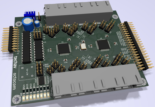
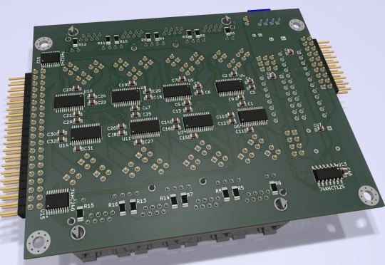
It ended up being a tight fit, but I was able to make it work on a 4-layer board within the same footprint of my main board, putting some components on the back side. (It may look like a bunch of empty space, but there's actually a lot going on running full RS232 with handshaking for 8 ports).
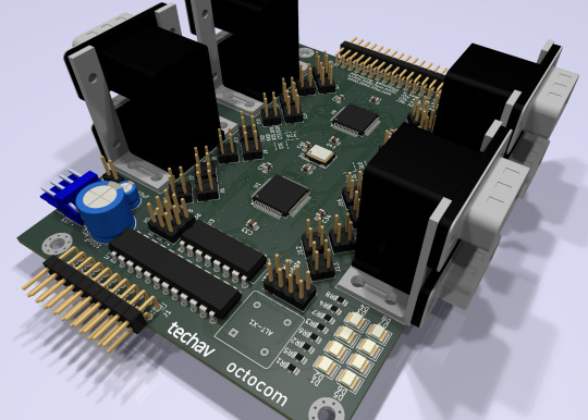
New problem. I had blown my budget for the project. As much as I love those stacked DE9 connectors, they're expensive. And there's no getting around the $10 pricetag for each of those quad UARTs. Even using parts on-hand where possible, I was looking at a hefty Mouser order.
[jbevren] suggested using ganged RJ45 connectors with the Cisco pinout instead of stacked DE9, to save space & cut costs. [Chartreuse] suggested buffering the TTL serial TX/RX signals to drive the LEDs that are frequently included on PCB-mount RJ45 connectors. Both great ideas. I was able to cut 20% off my parts order and add some nice diagnostic lights to the design.
Two weeks later, I received five new PCBs straight from China. I of course wasted no time setting into starting to assemble one.
I really set myself up for a challenge on this one. I learned to solder some 25 years ago and have done countless projects in that time. But I think this might be the most compact, most heavily populated, most surface mount board I've ever assembled myself. (There are 56 size 0805 (that's 2x1.2mm) capacitors alone!)


After a few hours soldering, I had enough assembled to test the first serial port. If the first port worked then the other three on that chip should work too, and there's a great chance the other chip would work as well.

And it did work! After some poking around with the oscilloscope to make sure nothing was amiss, I started up the computer and it ran just fine at 8MHz.
And at 16MHz.
And at 25MHz.
And at 32MHz.
And at 40MHz.
And almost at 50MHz!
Remember what I said about my timing graphs showing one wait state for 50MHz? The computer actually booted up and ran just fine at 50MHz. The problem was when I tried typing in a BASIC program certain letters were getting switched around, and try as I might, BASIC just refused to 'RQN' my program. It was pretty consistently losing bit 3, likely from that signal having to travel just a tiny bit farther than the others. A problem that will probably be resolved with an extra wait state.
Good enough for a first test! A few hours more and I finished assembling the card.

I did have some problems with cleaning up flux off the board, and I had to touch up a few weak solder joints, but so far everything seems to be working. I've updated my little multi-user kernel to run all 8 users from this new card and it's running stable at 40MHz.
I need to update my logic on the 22V10 to fix a bug in the wait state generator. I would love to see this thing actually running at 50MHz — a 25% overclock for the 40MHz CPU I am currently running. I also want to expand my little kernel program to add some new features like the ability to configure the console serial ports and maybe even load programs from disk.
I hope to bring this machine with a collection of terminals and modems this June to VCF Southwest 2025 for an interactive exhibit that can be dialed into from other exhibits at the show.
#wrap030#multi-user BASIC#EhBASIC#homebrew computer#motorola 68030#68030#mc68030#motorola 68k#vcfsw#vcfsw2025#Retrocomputing#rtc#retrotech crew
31 notes
·
View notes
Text
Looking Back
Today, 26 March 2025, is the tenth anniversary of the first time I put power to a Z80 microprocessor in a breadboard and watched it blink some LEDs.

Within a few weeks that Z80 would be completely surrounded by other chips and hundreds of wires to form my first functioning homebrew computer.

Another week and I was already removing a 68000 from a (presumed) dead motherboard, with grand ideas of moving up to the 16-bit era (but absolutely no understanding of what that would entail)

It would be another two years before the first time I put that 68000 in a breadboard and successfully used it to blink an LED.

By the time another year had rolled around that 68000 was living on a soldered breadboard and for the first time on one of my projects, it was running real software — EhBASIC.

Always looking to more challenging projects, while I was building with a 68000, I was already reading through the manual for the 68030 trying to understand how to build with a proper 32-bit microprocessor. Just one more year and I had that 68030 on a wire wrap board, blinking an LED.

The next year I was doing the most ridiculous thing I could think of — free-running a Pentium CPU on a wire wrap breadboard to blink an LED. Because I could.

By the end of the next year that 68030 had moved from its wire wrap board onto a proper printed circuit board — my first ever 4-layer PCB.

The next year saw the towering expansion of the 68030 build, adding new peripherals and functionality.

Another year and I had an all-new 68030 build on a Micro-ATX form-factor motherboard developed in just a couple months ahead of VCF Southwest 2023.

The next year I focused on developing software for my existing 68030 board stack, rather than building something new from scratch. I succeeded in developing a minimal multi-user kernel to run four instances of BASIC simultaneously.
All along in between working on these projects I have done component-level repairs on various computers, developed expansion cards for the Mac SE, built PCs both new and old, burned out hard, developed some smaller homebrew computers, had a lot of false starts, failed projects, and abandoned projects, and completed some massive projects in my day job.
Looking back at everything I've worked on over these past 10 years I am absolutely amazed at how far I have come and what I have been able to accomplish. Much of it I still don't understand how I managed to actually pull it off, and I'm not entirely sure I could duplicate my successes.
Here's to the next ten years
#homebrew computing#homebrew computer#retro computing#retrocomputing#ten years#learning new things#zilog z80#motorola 68k
80 notes
·
View notes
Text
Putting It All Together


I have a CPU board, I have an FPU board, and I have a video board. I know they all work; I know the CPU board works with the FPU board; I know the CPU board works with the video board. Time to bring them all together and see what happens.
It doesn't work.
Well that's disappointing. All the pieces work, and I can use one expansion board or the other, but if I try to use both together, the computer fails to boot.
It will still run if the address and data buses are connected to all three boards, but as soon as I connect the control bus to the third board, everything stops.
I tested the control bus signals one-by-one to see where things broke down. It wasn't RESET#, HALT#, or BERR# (though I really didn't expect them to be a problem). It wasn't the bus size selectors, R/W#, or the Address & Data Strobes. That really only left one thing — the DSACKx#, or Data Strobes Acknowledge, signals.
This is ... Not really surprising. I suspect that it was actually the DSACKx# signals that gave me so much trouble with my original prototype and with the 8kΩ pull-up resistors I used initially. These are wired-OR signals that get pulled low by peripherals or logic to acknowledge and end a bus transaction, and then the pull-up resistors return the signals to Vcc when de-asserted. With a lot of devices on the bus, or long signal traces, the capacitance starts to add up and a high resistor value for the pull-up can cause a slow rise time when the signal is de-asserted. If it gets too long, the CPU will detect the signal as still asserted when it starts the next bus transaction and end it really, resulting in the CPU reading garbage data from the bus.
There are a few ways I could fix this. I could use the equivalent of an AND gate to combine the disparate DSACKx# signals and send the result to the CPU, but this would require a significant amount of rework or even redesign. I could lower the pull-up resistance, but don't have any lower value SIP resistors or a good way to add parallel resistors to lower the value. Or I could try lowering the system clock speed to increase the timing tolerances.
That last option is easy — just replace the oscillator. I swapped out the 40Mhz oscillator for the next highest I had: 25MHz.
And it booted.
It's a little bit slower, but the computer is now running reliably with both the FPU and the Video board connected.
To make the most of the two boards together, I ported the Mandelbrot renderer from BASIC to 68k assembly using FPU instructions. The BASIC program renders a 60x22 image with 31 levels, output over serial as ASCII characters. My best time running the BASIC version was 14 seconds at 56MHz. This new assembly program renders a 160x100 image with 16 levels, output as video ... in just over four seconds at 25MHz.
That is an impressive time, but I'm hoping I can solve the problem with the DSACKx# signals so I can push the clock speed up again. I'd like to see how fast I can get this thing to run.
I also still want to modify EhBASIC to use the FPU. I'm interested to see what kind of a speed difference it would make running the original ASCII renderer.
#motorola 68030#motorola 68k#homebrew computer#vintage computer#BASIC programming#assembly programming#homebrew computing#motorola 68882
32 notes
·
View notes
Text
Extra Thinky Bits

Ever since I built my 68000 computer, I've used a BASIC Mandelbrot rendering program I got from RosettaCode as a test benchmark. On the 6MHz 68000 it took nearly 10 minutes to run. With the 68030 running at 56MHz using a 32-bit data bus with L1 cache enabled, the same BASIC program completed in around 14 seconds.
But we can do better. EhBASIC is written in assembly to use 32-bit single-precision floating point numbers internally, but all of its mathematical routines use the CPU's integer ALU. There are large sections of code that could theoretically be replaced by single instructions for the 68882 floating point math coprocessor (FPU).
Adding the FPU is where I stopped on my original wire-wrapped prototype. I simply never could get it working reliably. I've since learned that I had some logic errors that were probably causing more trouble than my chosen method of prototyping. But this meant it was probably best to start over, and if I'm starting over, a custom PCB with a CPLD to handle logic & timing would be much easier, much more flexible, and much more reliable.
Another tumblr user, Avics1967, had pointed out that logic error to me a while back. It turns out the 68882 FPU is picky about the setup time relationship between the FPU's Chip Select signal and the CPU's Address Strobe signal. Basically, the Chip Select signal can't be transitioning at the same time that the Address Strobe signal is falling, and there's a few nanoseconds on either side of that AS# transition where the CS# signal must be stable. My original design didn't take this into account.
This setup time target ended up being harder to hit than I anticipated. With my little system running at 40MHz, there is just 12.5ns between the CPU asserting the address bus and the CPU asserting its Address Strobe. I need to allow about 3ns for the FPU Chip Select signal to be stable before AS# falls.
I'm using a 10ns CPLD for logic.
My first draft for the logic also did not meet timing requirements, and with my bus speed and parts on hand it never would. Luckily, the 68882 also supports what Motorola called "Late Chip Select", where the CS# signal could be asserted after AS#. So that's what I ended up doing — I implement a delay synchronous to the CPU clock to assert CS# half a clock after AS#.
I ran into an interesting problem while testing though. I assembled a short program to add 2+3 and store the result in memory where I could check if the result of 5 was stored properly. What I got instead was an endless chain of bus errors. If I hit reset quickly enough I could see the very first error was actually an Address Error, and then came the endless chain of Bus Errors.
This made no sense. The FPU can generate some exceptions, like the Coprocessor Protocol Violation I had gotten with my last prototype. And if there was a problem with my logic, a Bus Error might be thrown if the FPU wasn't detected or didn't respond in time. But an Address Error?
Turns out the FPU wasn't the problem at all. There was a typo — a single missing # — in my monitor which caused the CPU to try to load an odd instruction as a pointer instead of the actual pointer to the exception handler routine. So something was indeed causing an exception, but I couldn't see what the exception actually was because it was immediately followed by an Address Error which also spawned a Bus Error.
Thankfully, my exception table is in RAM, so I was able to patch it live before running my test program. And the next time I tried testing the FPU? It worked!
I have no idea what was causing the initial exception, but the FPU has been working for me since.
Now it's time to write some more sophisticated programs to really test the FPU, and maybe modify BASIC to use the FPU instead of its built-in arithmetic functions.
37 notes
·
View notes
Text
Serial Expansion
TSMON, the ROM monitor I'm running on my 68030 board, is designed to use two serial ports — one for the primary console, and one for an attached development computer. I've only ever used it with a single serial port. It would be useful to have a second for loading programs straight into memory. My 68030 board only has a single UART footprint, but why should that stop me?


I built a breakout board that plugs into the socket for the existing UART and adds a second. It holds a pair of 6850 UARTs, a 74'139 for address decoding, and a MAX232 level shifter. I even added some jumpers to disable the second UART if necessary.
It worked without issue with just the first UART populated, and the second UART did not interfere with the first one when it was added.

I've updated TSMON to add back in code for the second serial port which I had previously removed. I also edited the EhBASIC VEC_IN routine to check both serial ports for data. Now I can send BASIC programs over serial from another computer then run them using a terminal connected to the first serial port on the 68030 board.
18 notes
·
View notes