#Flexible Expanded Pure Graphite Packing
Explore tagged Tumblr posts
Visit Tumblr Blog
Explore Tumblr blogs with no restrictions, modern design and the best experience.
Last Seen Tumblr Blogs


Fun Fact
12.7% of mobile users access Tumblr.
Text
Graphite Packing vs PTFE
Summary
Graphite Packing and PTEF or Polytetrafluoroethylene Packing are very famous sealants which are usually available in braided style. The biggest difference between these packings is that the graphite is a naturally occurring form of carbon while PTFE is a synthetic material. Yarns have to go through several heat treatments to be shaped and structured of the desired packing features.
Picture Courtesy: JD Jones
Now let’s understand Graphite Packing vs PTFE on the following basis:
1. Composition- Graphite is the Inorganic form of pure carbon. Graphite packings are dark-colored braided sealants made of pure carbon. These can be blended with different elements or PTFE for feature enhancement.
PTFE is a while colored synthetic polymer which is made by polymerization of tetrafluoroethylene. These yarns can be lubricated for flexible packing with more properties.
2. Applications- Graphite packages are most suitable for agitator use, valves and shafts that handle acids, chemicals, etc. These are also used for the application that includes high pressure, temperature and shaft speed.
PTFE sheet manufacturers too serve clients dealing with fuel gases, mineral and synthetic oils and more. But these packings are used for industrial purposes that deal with corrosive substances and oxidizers apart from molten alkali metals and most importantly they are used for safe handling and management of highly reactive substances.
3. Properties- The High-Quality graphite yams are together braided to make graphite packings. They have a low coefficient of friction. Graphite packings are a good conductor of heat. The other is strong resin also with low coefficient of friction. PTFE is highly resistant to several types of substances like aggressive chemicals, gases, acids, etc.
4. Benefits- Expanded Graphite packings are the best alternatives to asbestos packings. Simplified installation and fast maintenance are a few of the advantages of graphite packings.
PTFE packings have a longer durability due to their cheap coefficient of friction. Omni-Yam packings with PTFE can be designed according to FDA requirements that can be used for edible & pharmaceutical products.
Conclusion
Graphite Packings can be treated with PTFE for better benefits like preventing color contamination, gaining better stability and many more. Both PTFE and Graphite packings are cost-efficient as both of these require low maintenance and are durable.
A wide range of fluid sealants is easily available in the market. And choosing the perfect packing depends on the pH, shaft speed and temperature required. It is also better to look into the chemical and thermal characteristics of the braided yams that is the basis of the properties of the packings.
1 note
·
View note
Photo

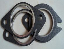
Asbestos Self Lubricated Graphite Packing
Visit For More Details: https://bit.ly/2C2ruBy
#Puregraphitepacking ��#Lubricatedgraphitepacking
#Manufacturer of PTFE Graphite Packing#Graphite Lubricated Ceramic Fiber Rope#Flexible Expanded Pure Graphite Packing#Manufacturer of Pure Graphite Packing
0 notes
Photo


PTFE sheet,PTFE sheet,Non asbestos rubber plate,Non-asbestos rubber sheet,asbestos reinforced composite plate, enhance the non-asbestos composite panels, Reinforced graphite sheet,Flexible thermal graphite roll, Non-Asbestos Beater Jointing Sheets,Carbon fiber packing,PTFE graphite braided packing, expanded graphite packing,high temperature and high pressure valves special packing,Aramid Fiber Packing, Pure PTFE packing,Asbestos rubber gasket,Non-asbestos rubber gasket,reinforced asbestos gaskets, reinforced asbestos gaskets,etc from chinese factory.www.yunyao-seal.com/en/,whatsapp, wechat:008613512159475,[email protected]
0 notes
Text
Graphite Packing vs PTFE
Summary
Graphite Packing and PTEF or Polytetrafluoroethylene Packing are very famous sealants which are usually available in braided style. The biggest difference between these packings is that the graphite is a naturally occurring form of carbon while PTFE is a synthetic material. Yarns have to go through several heat treatments to be shaped and structured of the desired packing features.

Picture Courtesy: JD Jones
Now let’s understand Graphite Packing vs PTFE on the following basis:
1. Composition- Graphite is the Inorganic form of pure carbon. Graphite packings are dark-colored braided sealants made of pure carbon. These can be blended with different elements or PTFE for feature enhancement.
PTFE is a while colored synthetic polymer which is made by polymerization of tetrafluoroethylene. These yarns can be lubricated for flexible packing with more properties.
2. Applications- Graphite packages are most suitable for agitator use, valves and shafts that handle acids, chemicals, etc. These are also used for the application that includes high pressure, temperature and shaft speed.
PTFE sheet manufacturers too serve clients dealing with fuel gases, mineral and synthetic oils and more. But these packings are used for industrial purposes that deal with corrosive substances and oxidizers apart from molten alkali metals and most importantly they are used for safe handling and management of highly reactive substances.
3. Properties- The High-Quality graphite yams are together braided to make graphite packings. They have a low coefficient of friction. Graphite packings are a good conductor of heat. The other is strong resin also with low coefficient of friction. PTFE is highly resistant to several types of substances like aggressive chemicals, gases, acids, etc.
4. Benefits- Expanded Graphite packings are the best alternatives to asbestos packings. Simplified installation and fast maintenance are a few of the advantages of graphite packings.
PTFE packings have a longer durability due to their cheap coefficient of friction. Omni-Yam packings with PTFE can be designed according to FDA requirements that can be used for edible & pharmaceutical products.
Conclusion
Graphite Packings can be treated with PTFE for better benefits like preventing color contamination, gaining better stability and many more. Both PTFE and Graphite packings are cost-efficient as both of these require low maintenance and are durable.
A wide range of fluid sealants is easily available in the market. And choosing the perfect packing depends on the pH, shaft speed and temperature required. It is also better to look into the chemical and thermal characteristics of the braided yams that is the basis of the properties of the packings.
0 notes
Text
PTFE vs. Graphite Packing
Summary

Graphite packings and PTFE Packings are popular sealants generally available in braided style. The biggest difference between these- graphite is a naturally occurring form of carbon and PTFE is a synthetic material. Yarns go through multiple heat treatments to get the shape and structure of the desired characteristics of packings.
Let’s understand PTFE vs Graphite Packings
Composition
Graphite is an inorganic form of pure carbon. Graphite packings are black-colored braided sealants made using pure carbon. They can be blended with other elements or PTFE for enhanced features.
PTFE stands for Polytetrafluoroethylene. It is a white-colored synthetic polymer made through polymerization of tetrafluoroethylene. PTFE can be further lubricated to make flexible packings with better properties.
Properties
High-quality graphite is braided together to form Graphite packings. They have a very low coefficient of friction. Graphite packings can be a conductor of heat. PTFE is a strong resin with a low coefficient of friction as well. It is highly resistant to different kinds of substances such as aggressive chemicals, acids, gases, etc.
Teflon is a variant of PTFE that is widely used for making non-stick cookware.
Applications
Graphite packings are suitable for use in agitators, valves, and shafts that handle chemicals, acids, etc. PTFE Sheet manufacturers also deal with fuel gases, mineral and synthetic oils, steam water, effluents and more.
PTFE packings are used in industrial plants that deal with corrosive substances and oxidizers except for molten alkali metals. They are utilized in pharmaceutical, food, aerospace, electrical and many other industries. PTFE envelope gaskets are used in industrial plants for safer handling and management of highly reactive substances.
Benefits
Expanded Graphite packings are perfect alternatives to asbestos packings. PTFE has a longer shelf life due to its lower coefficient of friction. Multi-yarn packings with PTFE can be designed as per FDA requirements to be used for edible products and pharmaceutic contamination, gaining better stability, etc. Both graphite and PTFE packings are cost-effective as they both are durable and require low maintenance. A wide range of fluid sealants is available in the market. It is also better to look into the thermal and chemical properties of the braided yarns that influence the properties of the packings.
Conclusion Graphite packing is a highly resistant used in systems with valves, faucets, and stuffing boxes, as well as other machines with watertight mechanical parts. PTFE is a tough,non-resilient material, flexible with great thermal properties and excellent resistance to chemicals. The coefficient of friction is low and believed to be lower than any other solids.
0 notes
Text
Interview with Prof. Andreas Hintennach - head of battery cell research at Daimler
The battery system is perhaps the most critical component of battery electric vehicles. In addition to obtaining the highest possible energy density, aspects such as safety, weight and sustainability play crucial roles. Prof. Dr. Dr. Andreas Hintennach is head of battery cell research at Daimler. In addition to explaining the fundamentals of current lithium-ion cells, he outlines which future technologies actually have a chance.
The battery system is a key element of electric mobility. Every day at Daimler, experts from various disciplines deal with all aspects of this storage technology, from basic research to production maturity. The requirements are complex, and vary depending on the application. This is because 48-volt mild hybrids, plug-in hybrids, and purely electric drivetrains require different development focuses. In order to maintain an overview of this hotly debated topic, Andreas Hintennach gave media representatives an insight into the technical principles as well as Daimler development and research goals during a digital roundtable.
Professor Hintennach, you are working on the research and development of batteries – the current “hot” topic in terms of e-mobility. How is Mercedes-Benz tackling this topic?
Battery technology is a key element of electric mobility and not an off-the-shelf product, but an integral part of the vehicle architecture. Therefore we cover all stages from fundamental research to production maturity. Our activities include the continuous optimization of the current generation of lithium-ion battery systems, the further development of cells available on the world market and research of next-generation battery systems. But of course, there’s more when it comes to batteries for electric vehicles. We are also working on the battery management system, which is a complex computer that you can always improve on. Thermal management is an important topic as well. It is responsible for the life and also the performance of the battery pack. You have to really understand the mechanism of technologies in order to be able to make the right decisions.
What is your current focus?
While our all-new EQC model is being introduced to the markets, we are preparing the way for next generations of powerful battery-electric vehicles. Lithium-ion batteries are the most common type used in electronics and electric vehicles today. In the years ahead, this technology will continue to set the pace – but there is more to come. Regarding research and development, we follow several specific guiding principles. We are consistently working on innovation and alternatives beyond lithium-ion – not least regarding energy density and charging time, but also sustainability. For example, we have agreed on a sustainability partnership with Farasis Energy (Ganzhou) Co., Ltd. to take a holistic approach along the entire value chain: part of the battery cells for the next vehicle generation of our EQ product and technology brand are already to be produced using 100 percent electricity from renewable energies. Our competencies for the technological evaluation of materials and cells as well as research and development activities are being consistently expanded.
So it is more than just about increasing the kWh per battery pack?
Energy capacity is important, of course. But there is more to it: safety is a very decisive factor for us. Material related changes could make it possible to obtain a higher capacity – but with compromises in terms of safety. For us, this is definitely out of the question. A Mercedes-Benz has to be the benchmark when it comes to safety, and this also goes for its battery pack. One of our guiding principles of development is also flexibility: at Daimler, there are a lot of use-cases for battery packs, from the smart to Mercedes-Benz cars and vans – to buses and heavy trucks – and finally from 48-volt mild hybrids to plug-in hybrids and purely electrical cars. And of course, the solutions we come up with must be sustainable.
How important is sustainability in development?
Sustainability has become the overarching principle for any development activity at Daimler. Since the manufacture of vehicles naturally requires a high amount of raw materials, one of our development focuses is on minimizing the need for natural resources, but also to increase transparency at first. During development, we create a concept for each vehicle model in which all components and materials are analyzed for their suitability in the context of a circular economy. Concerning batteries, this concept is already used for fundamental research in which precious materials can be substituted, minimized or used more efficiently. What’s more, recyclability is already taken into account from beginning. So battery production becomes a part of a holistic approach – a closed loop; a so-called circular economy.
What is the environmental impact of electric vehicles? Electric propulsion has a demonstrably worse impact than combustion engines when it comes to production.
The production of the combustion engine has been steadily improved over the past 133 years. The battery and the fuel cell, on the other hand, currently start life with more emissions due to the increased energy requirement. However, in terms of operation they are both much more efficient. And that pays off in the long run. Even if we do not charge them using CO₂-neutral electricity, battery-powered vehicles generate around 40 percent fewer emissions over their life cycle than vehicles with gasoline engines, and 30 percent less than diesel-powered vehicles. And in this calculation, our target CO₂ reductions for production by 2039 and the recycling of raw materials that will be incorporated into the production cycle in the future are not even taken into consideration. Both will further improve the sustainability of our vehicles holistically, and in so doing contribute to our “Ambition2039”. Today, our vehicles are already 95 percent recoverable.
How long will it be until a market for secondary raw materials is in place?
In eight to ten years there will be a significant number of vehicle batteries available for recycling. Then in particular cobalt, nickel, copper, and later also silicon will be recycled. We are already very well prepared and the processes are in place, as are the opportunities for returning secondary raw materials into the production cycle. We currently do this with our test batteries. The establishment of a functioning market for secondary raw materials for Europe is of great political importance, because Europe barely has any primary sources. But we are of course doing everything we can to ensure that batteries last as long as possible.
What materials are used in the battery?
With lithium ion technology the cell structure is always similar, regardless of whether it is a cell phone or an EV battery. There are always two metal sheets, such as copper and aluminum. Between the metal sheets are the two poles with the cathode and anode, among which the electric reaction takes place. For the reaction a reactive metal such as lithium is required. The biggest cost factor is the composition of the cathode, meaning the positive pole of the battery. It consists of a mixture of nickel, manganese and cobalt. The anode is made from graphite powder, lithium, electrolytes and a separator.
And where does the aforementioned silicon come into play?
Silicon will largely replace graphite powder in the future. This will enable us to increase the energy density of batteries up to about 20 to 25 percent. Silicon allows us to use materials on the cathode side that are not compatible with the graphite that is currently used. Imagine two glasses. If you want to pour water from one into the other, the second should at least be the same size so that it does not overflow. Similarly, the anode and the cathode should harmonize, which we call ‘balancing’. Silicon is also used, however, to improve the speed of charging.
An important cue: Cobalt is frequently associated with violations of human rights and damage to the environment in connection with its extraction, particularly when it stems from the Democratic Republic of Congo. What is Daimler doing about this?
We have developed an approach that is aimed at making sure that our suppliers meet our requirements with respect to sustainability, and in doing so aim to achieve greater transparency in the supply chain. To this end, we have engaged an audit company to clarify and monitor every stage of the cobalt supply chain in accordance with OECD standards. After all, electromobility is only truly sustainable if the raw materials are extracted under sustainable conditions.
Another strategy is to replace cobalt with other, less critical materials …
We are doing research on that. With the current generation of battery cells, we have already been able to reduce the proportion of cobalt in the active material (nickel, manganese, cobalt, lithium) from around a third to less than 20 percent. In the laboratory we are currently working with less than ten percent and the share is set to fall even more in the future. From a chemical perspective there are a lot of arguments for abstaining cobalt entirely. The more the mixture of materials is reduced, the easier and more efficient it is to recycle. The energy required for chemical production is also reduced because the mixture is easier to produce.
What will replace cobalt and other materials like Lithium?
They are materials that are mainly based on manganese - a raw material that is less troublesome from an ecological perspective and easier to work with. Excellent recycling facilities are already in place for manganese because it has been used for decades in the form of alkali batteries (non-rechargeable batteries). The task for researchers is to make this type of battery chargeable. We expect the technology to be ready for market by the second half of the 2020s. Another alternative is the lithium/sulfur battery. Sulfur is an industrial waste product with almost no costs that is very pure and can easily be recycled. It poses significant challenges with respect to energy density, but also has an unbeatable ecobalance. However, it may take years until this technology is available for passenger cars.
Lithium is also the subject of criticism. Can this raw material also be replaced?
It can. The magnesium-sulfur battery, for example, contains no lithium. We are familiar with magnesium from our everyday lives in the form of chalk. The big advantage is that it is freely available. The Swabian Alb consists entirely of chalk, for example. However, our research is currently at a laboratory stage.
So there are no alternatives to the lithium-ion battery at present?
There are, in some applications. There are even technologies that are superior to the lithium-ion battery. These include the solid-state battery, which we will be using in our Mercedes-Benz eCitaro urban bus within the second half of the 2020’s. The technology has a very long life cycle, and also does not include any cobalt, nickel or manganese. However, its energy density is lower, which makes it relatively large and slow to charge. That is why it is good for commercial vehicles but not for passenger cars. The lithium-ion battery will be with us for years to come.
What will be the next “holy grail”? Are solid-state batteries the future?
There is not one single post-lithium-ion technology. Be it cells with solid-state electrolytes, lithium metal anodes, or lithium sulfur systems - all technologies differ in their specific material requirements, their applications and not least their level of maturity. Each technology has its specific pros and cons. The good news is that there are multiple paths which lower the risk of a potential dead-end road in development. Not yet around the corner – but also not very far down the road – are batteries in which the graphite coating of the anode can be replaced with novel materials such as lithium-metal foil or silicon powder. Both increase energy density by far. This leads to higher range and could even support fast charging. All solid-state batteries have great advantages when it comes to safety, but we are still working on fast charging and a longer lifespan before we can say “this is the technology we should bring to the road now” regarding our passenger cars.
And what will happen further down the road?
Lithium-sulfur is one possible alternative. Replacing the nickel and cobalt of today’s batteries with sulfur would significantly increase sustainability. The energy density also has a lot of potential, but the lifespan is not yet long enough and it will take a while until there is a breakthrough in this area. In lithium-air batteries, there is really only lithium. The rest – the oxygen – simply comes from the air. Chemically, it’s a concept similar to what you have in a fuel cell, where we are using hydrogen. The energy density would be outstanding – but this technology is still quite far down the road.
With your research car VISION AVTR you went one step further, far beyond tomorrow. Is organic battery technology really an option?
With the VISION AVTR, Mercedes-Benz is presenting a sustainable vision of emission-free mobility - also when it comes to drive technology. For the first time, its revolutionary battery technology consists of organic-cell chemistry based on graphene and thus does not use any rare, toxic or expensive materials such as metals. This makes e-mobility independent of fossil resources. An absolute revolution is the 100 percent recyclability through composting due to the materiality - a prime example of a future circular economy in the raw materials sector. In addition to an exponentially high energy density, the technology also impresses with its exceptional quick charging capability. Organic batteries are currently part of our fundamental research. It will still take several years until it can be established in Mercedes-Benz vehicles - but the potential is there!
0 notes
Text
Comparison Between PTFE vs. Graphite Packing
For fluid sealing, different kinds of packings are used. Graphite packings and PTFE Packings are popular sealants generally available in braided style. The biggest difference between both these packings is that graphite is a naturally occurring form of carbon and PTFE is a synthetic material. Yarns go through multiple heat treatments to get the shape and structure of the desired characteristics of packings.
So let us compare PTFE with Graphite Packings on the basis of the following aspects:
Composition
Graphite is an inorganic form of pure carbon. Graphite packings are black-coloured braided sealants made using pure carbon. They can be blended with other elements or PTFE for enhanced features.
PTFE stands for Polytetrafluoroethylene. It is a white-coloured synthetic polymer made through polymerization of tetrafluoroethylene. A PTFE yarn can be lubricated to make flexible packings with better properties.
Properties
High quality graphite yarns are braided together to form Graphite packings. They have a very low coefficient of friction. Graphite packings can be a conductor of heat. PTFE is a strong resin with low coefficient of friction as well. It is highly resistant to different kinds of substances such as aggressive chemicals, acids, gases etc.
Teflon is a variant of PTFE that is widely used for making non-stick cookware. PTFE prevents wearing of shafts and also works as a very good insulation material for electrical uses. Multi-yarn packings are made using PTFE to get better strength and lubrication capabilities.
Applications
Graphite packings are suitable for use in agitators, valves, and shafts that handle chemicals, acids, etc. They are also used in applications that involve high pressure, greater shaft speed and high temperatures.
Expanded Graphite packings are used in steam turbines and high-temperature valves. PTFE Sheet manufacturers also serve clients dealing with fuel gases, mineral and synthetic oils, steam water, effluents and more.
PTFE packings are used in industrial plants that deal with corrosive substances and oxidizers except for molten alkali metals. PTFE Packings are ideal for most forms of aggressive media. They are utilized in pharmaceutical, food, aerospace, electrical and many other industries.
PTFE envelope gaskets are used in industrial plants for safer handling and management of highly reactive substances.
Benefits
Expanded Graphite packings are perfect alternatives to asbestos packings. Simplified installation and quick maintenance are some of the benefits of graphite packings.
PTFE packings have a longer shelf life due to their lower coefficient of friction. Multi-yarn packings with PTFE can be designed as per FDA requirements to be used for edible products and pharmaceutical products.
Graphite packings can be treated with PTFE to get better benefits such as preventing colour contamination, gaining better stability etc. Both graphite, as well as PTFE packings, are cost-effective as they both are durable and require low maintenance.
Conclusion
A wide range of fluid sealants is available in the market. Choosing the right packing depends on the pH, temperature and shaft speed required. It is also better to look into the thermal and chemical properties of the braided yarns that influence the properties of the packings.
0 notes
Text
PTFE vs. Graphite Packing

For fluid sealing, different kinds of packings are used. Graphite packings and PTFE Packings are popular sealants generally available in braided style. The biggest difference between both these packings is that graphite is a naturally occurring form of carbon and PTFE is a synthetic material. Yarns go through multiple heat treatments to get the shape and structure of the desired characteristics of packings.
Let’s understand PTFE vs Graphite Packings on the basis of the following aspects:
Composition
Graphite is an inorganic form of pure carbon. Graphite packings are black-colored braided sealants made using pure carbon. They can be blended with other elements or PTFE for enhanced features.
PTFE stands for Polytetrafluoroethylene. It is a white-colored synthetic polymer made through polymerization of tetrafluoroethylene. PTFE yarns can be lubricated to make flexible packings with better properties.
Properties
High-quality graphite yarns are braided together to form Graphite packings. They have a very low coefficient of friction. Graphite packings can be a conductor of heat. PTFE is a strong resin with a low coefficient of friction as well. It is highly resistant to different kinds of substances such as aggressive chemicals, acids, gases etc.
Teflon is a variant of PTFE that is widely used for making non-stick cookware. PTFE prevents wearing of shafts and also works as a very good insulation material for electrical uses. Multi-yarn packings are made using PTFE to get better strength and lubrication capabilities.
Applications
Graphite packings are suitable for use in agitators, valves, and shafts that handle chemicals, acids, etc. They are also used in applications that involve high pressure, greater shaft speed and high temperatures.
Expanded Graphite packings are used in steam turbines and high-temperature valves. PTFE Sheet manufacturers also serve clients dealing with fuel gases, mineral and synthetic oils, steam water, effluents and more.
PTFE packings are used in industrial plants that deal with corrosive substances and oxidizers except for molten alkali metals. PTFE Packings are ideal for most forms of aggressive media. They are utilized in pharmaceutical, food, aerospace, electrical and many other industries.
PTFE envelope gaskets are used in industrial plants for safer handling and management of highly reactive substances.
Benefits
Expanded Graphite packings are perfect alternatives to asbestos packings. Simplified installation and quick maintenance are some of the benefits of graphite packings.
PTFE packings have a longer shelf life due to their lower coefficient of friction. Multi-yarn packings with PTFE can be designed as per FDA requirements to be used for edible products and pharmaceutical products.
Graphite packings can be treated with PTFE to get better benefits such as preventing color contamination, gaining better stability etc. Both graphite, as well as PTFE packings, are cost-effective as they both are durable and require low maintenance.
A wide range of fluid sealants is available in the market. Choosing the right packing depends on the pH, temperature and shaft speed required. It is also better to look into the thermal and chemical properties of the braided yarns that influence the properties of the packings.
Learn more about different kinds of PTFE and Graphite packings, you can contact a reliable PTFE manufacturer such as Sealmax. To explore the products offered by Sealmax, visit www.sealmax.in
0 notes
Text
Aorus is a premium gaming brand spawned from GIGABYTE that has expanded to offering motherboards beginning with Intel’s 200-series chipset and Kaby Lake CPU release. On launch day, Aorus is introducing six Z270-based mainboards starting with the high-end Z270X-Gaming 9 all the way to their entry level Z270X-Gaming K5. Since Aorus is a Gigabyte brand, they share the same naming scheme and many of the same features that are familiar to many users despite being a new brand to the motherboard scene.
The Z270X-Gaming 5 is the lower mainstream 200-series mainboard offering from Aorus, second only to the Z270X-Gaming K5 in terms of affordability although you would not know it looking at the specifications sheet as it comes packed. Also, since it is a premium brand, it is priced differently with the Z270X-Gaming 5 actually priced at $195 so it is on par with many higher mainstream Kaby Lake motherboards. The Z270X-Gaming 5 features dual-Gigabit LAN using Intel and Killer NICs, Realtek ALC1220 HD audio codec, USB 3.1 Type-C, on-board U.2 and dual M.2 slots. Building upon Gigabyte Z170 motherboard features, the Aorus Z270X-Gaming 5 also features improved smart fan functions and management via Smart Fan 5 and improved RGB LED implementation with RGB fusion having multiple light zones and multiple modes, effects as well as flexible customization.
[sc:sponsor sponsor=”AORUS” product_link=”http://www.aorus.com/” product_name=”Z270x-Gaming 5″ product_price=”$195″ ]
The Z270X-Gaming 5 motherboard sports a black box with an orange accent with the Aorus logo front and center in the middle although a small Gigabyte is also present on the side familiar tomost. All the promotional information are in the rear outlining some of the Z270X-Gaming 5 motherboard’s unique features including USB DAC Amp, RGB Fusion and more.
#gallery-0-41 { margin: auto; } #gallery-0-41 .gallery-item { float: left; margin-top: 10px; text-align: center; width: 50%; } #gallery-0-41 img { border: 2px solid #cfcfcf; } #gallery-0-41 .gallery-caption { margin-left: 0; } /* see gallery_shortcode() in wp-includes/media.php */
The contents inside the box are stored in two compartments. The top area contains the motherboard housed inside an anti-static bag while underneath all the accessories are individually packed and stored.
Aside from the essential drive disc (It is 2016, why can’t these things come in USB drives instead?), installation guide and IO shield. Gigabyte includes four black SATA cables (two of which have one 90-degree end), a Gigabyte G-connector for the front IO, an Aorus case badge, and a 4-pin RGB LED extension cable. Since this is a pre-production model, there is no user manual pictured here but it should be available for download on the product page or bundled with the motherboard when you purchase it in store.
The Aorus Z270X-Gaming 5 motherboard uses an ATX form factor measuring 305 x 244mm with a matte black 6-layer PCB and brushed aluminum black anodized heatsinks. The DIMM and PCI-E x16 slots are also equipped with a shiny “armor” reinforcement. On the right side edge is an obvious strip of LED and there are more outlining the audio area on the other side.
[section_title title=Introduction and Packaging] [section_title title=A Closer Look at the Gigabyte Z270X-Gaming 5 Motherboard]
A Closer Look at the Gigabyte Z170X-Gaming 5 Motherboard
A white IO cover is pre-installed as a cosmetic feature, but this can be removed via screws in the rear.
#gallery-0-42 { margin: auto; } #gallery-0-42 .gallery-item { float: left; margin-top: 10px; text-align: center; width: 33%; } #gallery-0-42 img { border: 2px solid #cfcfcf; } #gallery-0-42 .gallery-caption { margin-left: 0; } /* see gallery_shortcode() in wp-includes/media.php */
The VRM coolers are made up of two identical, non-heatpiped pieces weighing 64 grams and 51 grams. These are black anodized aluminum heatsinks with a white accent plus thin brushed metal sheet design glued on top so it is easily moddable. Aorus uses a thick gray thermal tape in between the MOSFETs and the heatsink.
The chipset heatsink weighs 45 grams and the accent on it can be removed or modded in the same way as the VRM heatsink. A thin graphite thermal sheet is used as an intermediary between the chipset and this heatsink instead of a thicker thermal tape or thermal interface paste. The audio armor piece weighs 15 grams and does not act as a heatsink of any sort. It is purely cosmetic and easily moddable as well considering it mounts easily via screws from the rear.
The space is very generous for the RAM clearance at 32.2mm compared to many motherboards that are 27mm or under. The layout is also quite similar to the Z170X-Ultra Gaming with the M.2 slot directly positioned right above the top-most PCI-E x1 slot and below the CPU socket where the bank of linear regulartors and MOSFETs for the minor CPU rails are. This M.2 slot supports up to 110mm long devices. Unlike the Z170X-Ultra Gaming motherboard however, the Z170X-Designare is equipped with the “Turbo B-clock” IC (it is hidden underneath a shiny metal housing), a secondary clock generator for refined BCLK overclocking.
The main PWM controller is an Intersil ISL95866, a dual-output 4+3 phase capable IMVP8 controller from Intersil for the CPU+GT.There are three integrated drivers in total on this controller, two of which are on one output (voltage regulator A) while the third one is can be used on the voltage regulator that can be configured up to three phases. All of these drivers are used and additional Intersil ISL6625A drivers are utilized to drive Vishay SiRA18DP and SiRA12DP TrenchFET MOSFETs. Output filter has custom 500nH chokess with 561uF Japanese FP caps.
The 8-pin EPS12V CPU power connector is at the top right corner, tightly squeezed right above the VRM heatsink and beside two chokes. Gigabyte was wise to make the latch for this power connector facing upward so it is easier to release later during uninstallation. The 4-pin fan header for rear placed exhaust fans is positioned further down closer to the bottom edge of the rear IO.
The DIMM slots have a metal “armor” around them and only lock on the top end part while the bottom part is fixed. A Richtek RT8120D is used for the memory VRM with three SiRA12DP FETs, a pair of 561uF FP caps and a 1KnH choke. Another 4-pin fan header is located here, right below the 24-pin connector. An OC switch an and ECO mode switch is located on the top right corner. These are for quick switching to preset configurations like in the UEFI EZ mode screen.
Onboard storage begins with a pair of 19-pin USB 3.0 header right below the 24-pin power supply connector. This is natively from the chipset. Also provided are six SATA3 headers, two pairs of are angled which can be used as SATA Express, although do not hold your breath for any SATA Express devices any time soon. What is exciting however is the inclusion of an embedded U.2 connector.
One m.2 slot is located right below the CPU socket which can also be used with an m.2 to U.2 Mini-SAS add-in card. It can be plugged into one of these m.2 slots and be able to run up to three NVMe SSDs in RAID 0 (M.2 or M.2 with U.2 converter + U.2 + PCI-E). This slot also supports 22110 form factor M.2 cards in length.
If a drive is installed on the bottom-most PCI-E slot, SATA ports 0 and 1 are disabled, using ASMedia ASM1480 switches to toggle. Even if it isn’t an SSD installed here, as long as this slot is populated, SATA ports 0 and 1 are disabled. You can see that Gigabyte has prioritized the storage plexing so that it has as little interference to the rest of the lane allocation besides the SATA ports.
Along the bottom right corner is the front panel header but this should be very easy to spot considering it is marked with the polarity and color coded. The G-connector accessory also makes installation easier. There is clear CMOS jumper header right above the front panel header bank. There is also a thunderbolt connector header available for a Thunderbolt add-in card. Another PCIe Gen3 x4 M.2 slot is located right between the second and third PCIe x16 slots. This one however is limited to 2280 form factors due to a PCIe x1 slot on the way.
Expansion slot distribution is as follows (in order top to bottom):
PCI-E 3.0 x1 via Z170
PCI-E 3.0 x16 via CPU (x16, x8 when slot 4 is populated, switched by ASMedia ASM1480’s)
PCI-E 3.0 x1 via Z170
PCI-E 3.0 x16 via CPU (x8)
PCI-E 3.0 x1 via Z170
PCI-E 3.0 x16 via Z170 (x4, shares bandwidth with SATA 0, 1)
The Z270X-Gaming 5 motherboard’s PCI-E retention slots are reinforced with soldered-through shielding. This prevents the motherboard from getting damaged just in case something heavy drops on your video card that dislodges it.
The rest of the headers along the bottom include a pair of 9-pin USB 2.0 headers, a trusted platform module header, RGB LED header and front panel audio headers with SPDIF output. The RGB LED header is for connecting RGB LED strips which then can be controlled in sync with the Aorus Z270X-Gaming 5 either via the RGB LED options under the UEFI or the desktop software application.
The audio subsystem is physically isolated from the rest of the PCB and audio is handled by a Realtek ALC1220 HD Audio codec capable of up to 32-bit playback unlike the popular Realtek ALC1150. This audio subsystem lights up with RGB LEDs (set to red by default) lined up at the rear of the PCB that shine through the isolation border. Nippon Chemicon audio capacitors are used for filtering in this area and a Texas Instruments NE5532P amp is used for the rear IO audio output which is socketed and can be replaced if wanted. There is also a gain adjustment switch right at the bottom for the front audio panel.
The rear PS2 port is provided by an ITE8686E Super IO chip which also handles system and temperature monitoring functions. There are two Gigabit Ethernet NICs included on the Aorus Z270X-Gaming 5, one is Intel’s latest “Jacksonville” i219-V PHY while the other is a Killer E2500.
#gallery-0-43 { margin: auto; } #gallery-0-43 .gallery-item { float: left; margin-top: 10px; text-align: center; width: 50%; } #gallery-0-43 img { border: 2px solid #cfcfcf; } #gallery-0-43 .gallery-caption { margin-left: 0; } /* see gallery_shortcode() in wp-includes/media.php */
There is a DisplayPort 1.2 (Maximum resolution supported is 4096×2304@60Hz and an HDMI 1.4 port supporting 4096 x 2160 @ 24Hz.
#gallery-0-44 { margin: auto; } #gallery-0-44 .gallery-item { float: left; margin-top: 10px; text-align: center; width: 50%; } #gallery-0-44 img { border: 2px solid #cfcfcf; } #gallery-0-44 .gallery-caption { margin-left: 0; } /* see gallery_shortcode() in wp-includes/media.php */
For rear audio, there are five configurable analog audio jacks with one optical audio out with all the analog jacks having gold plating. The yellow USB ports in the rear have the USB DAC-AMP function configuratble in the BIOS or via the Aorus DAC-AMP desktop software. Two USB 3.1 Gen 2 ports are provided, one Type-C and one Type-A via ASMedia ASM2142 controller.
[section_title title=Bundled Software and UEFI Overview]
Bundled Software
Gigabyte App Center
The App Center is a one-stop launch pad for the Gigabyte bundled software. It sits on the Windows system tray and opens up to a translucent floating window from where users can launch the Gigabyte applications installed. All the applications are Windows 10 compatible and verified in this review. Users can adjust the colors to fit the various Gigabyte theme colors including blue, orange, green and red. Gigabyte’s Easy Update is also now integrated into the APP Center, so users can update directly from the launching pad. These are all similar to previously reviewed Gigabyte motherboards so check out what the rest of those features are by clicking here, otherwise, we’ll go over the new features that are exclusive on the Aorus Z270x-Gaming 5 motherboard.
RGB Fusion
The RGB Fusion software is a severely upgraded control center for RGB lighting onboard and connected to the AORUS Z270 mainboard compared to 100-series Gigabyte units. First, of all it is extremely snappy and responsive and much lighter compared to the previous RGB controller app. There is also an incredible amount of options as well as zone control now beyond just simply picking a color and preset. Up to three profiles can be saved and customized.
#gallery-0-45 { margin: auto; } #gallery-0-45 .gallery-item { float: left; margin-top: 10px; text-align: center; width: 50%; } #gallery-0-45 img { border: 2px solid #cfcfcf; } #gallery-0-45 .gallery-caption { margin-left: 0; } /* see gallery_shortcode() in wp-includes/media.php */
Similarly in the UEFI, there is also a feature like this present under peripherals but it is much more basic and was similar to Gigabyte’s 100-series RGB lighting controls.
The Smart Fan options are also new, now providing a graphical custom fan curve for users to adjust plugged in fans. This has been improved and allows users to set and monitor zones on the motherboard depending on where the fan is located on the case. There is both a UEFI and a desktop version inside the System Information Viewer software.
The USB DAC has also received a software control option on the desktop, allowing users to adjust the voltage or disable it entirely on all three output headers available.
UEFI Overview
This Easy Mode shows a single page overview of basic customizable settings as well as a quick monitoring of CPU, system temperature and plugged-in components. Each setting can be expanded with the click of the top right corner of each tab.
Classic mode:
The first default screen is the System Information tab. No information can be changed here other than system language, access level as well as date and time. This is actually the second tab in the Classic mode menu. A hidden menu showing the current system settings are also available to the right and other embedded UEFI features are accessible via a hidden menu on the bottom.
The Motherboard Intelligent Tweaker or M.I.T. tab is where users can overclock their CPU from. All the overclocking settings you need are in this tab including fan control for keeping the thermal levels in check. There are six sub-menus for adjustments here including a redundant Smart Fan settings option.
#gallery-0-46 { margin: auto; } #gallery-0-46 .gallery-item { float: left; margin-top: 10px; text-align: center; width: 20%; } #gallery-0-46 img { border: 2px solid #cfcfcf; } #gallery-0-46 .gallery-caption { margin-left: 0; } /* see gallery_shortcode() in wp-includes/media.php */
M.I.T.\Advanced Frequency Settings>:This is where overclocking values are changed with options to adjust CPU Base Clock, Integrated Graphics Slice and Unslice ratios , Memory multiplier and a sub-menu for enabling or disabling CPU-specific features. Users can use the PAGE UP or PAGE DOWN keys to increase or decrease values or just simply enter numerical values directly.
M.I.T.\Advanced Memory Settings>: This is the page for memory overclocking and timing adjustment and allows for memory divider setting up to 4133MHz
M.I.T.\Advanced Voltage Settings>: This page is for adjusting all the voltage related settings and there are five sub-menus to choose from depending on what to adjust. Advanced Power Settings is where Load Line Calibration is adjusted for the CPU and IGP (AUTO, Standard, High and Turbo).
Now onto the rest of the UEFI layout. The third tab is the BIOS features page which allows users to change boot priorities and set other boot options.
The fourth tab is the Peripherals tab which has the bulk of the motherboard related functions including enabling/disabling hardware such as USB, SATA, display and provides LED control.
The fifth tab is the Chipset page which toggles features on both the Z270 chipset and CPU northbridge such as internal graphics, audio controller, VT-d and PCH LAN Controller.
The sixth tab is the Power Management page which enables or disables power saving features as well as several platform power options.
The last page is the Save and Exit page where users can save and exit or save as well as load a profile locally. As with every decent exit page, there is a quick single-click boot override option.
[section_title title=Test System and Testing Procedures]
Test System and Testing Procedures
Item Name Processor Intel Core i7-7700K, Intel Core i7-6700K (Z170 motherboards) CPU Cooler Noctua NH-D15S Power Supply Corsair HX850W 80 Plus Gold PSU Memory Kingston HyperX Fury DDR4 2x8GB @ 2666MHz 15-17-17-35 2T (XMP) Storage Silicon Power S80 240GB SSD (OS), OCZ Vertex 4 256GB SSD (Test) Graphics Integrated CPU Graphics, Gigabyte GTx 960 Windforce 3x OC Router Cisco E3200 stock firmware with 2x 6ft Cat5E cables for network testing Motherboard(s) Gigabyte Z170X-Designare (BIOS F2), Gigabyte Z170X-Ultra Gaming (BIOS F4)Gigabyte Z170X-UD5 (BIOS F4), EVGA Z170 FTW (BIOS v1.03), Gigabyte Z170-Gaming 7 (BIOS F2) Operating System Windows 10 Enterprise*
Latest working BIOS, updates and drivers were used at the time of the review. Each test was conducted at least three times for accuracy with the exception of PCMark 8 which already does three sets per benchmark run. *All performance benchmarks in this review and all reviews going forward will be using the Windows 10 operating system.
System Benchmarks
Aida64 Engineer
SiSoft Sandra Lite 2016
CineBench R15
PCMark 8
WinRAR
x.264 FHD
Gaming Benchmarks
3DMark Firestrike (Default)
Unigine Heaven 4.0 (Max Settings, 1920 x 1080)
Bioshock Infinite (Lowest Settings @ 640 x 480, Max Settings @ 1920 x 1080)
[section_title title=System Benchmarks (CPU, Memory, Compression, Multimedia)]
System Benchmarks
The AIDA64 suite has various benchmarks for CPU, FPU and memory testing: CPU Queen is an integer benchmark that tests branch prediction and misprediction penalties. CPU PhotoWorxx tests the SIMD integer arithmetic execution units of the CPU and the memory subsystem. CPU ZLib is a compression benchmark that tests the combined CPU and memory performance. CPU AES is a multi-core encryption benchmark that uses Advanced Encryption Standard data encryption. CPU Hash is an integer benchmark that measures performance using SHA1 hashing algorithm. FPU Julia measures single precision FP, FPU Mandel measures double precision FP, FPU SinJulia measures extended precision FP while FPU VP8 is a video compression test utilizing the FPU Julia fractal module.
#gallery-0-47 { margin: auto; } #gallery-0-47 .gallery-item { float: left; margin-top: 10px; text-align: center; width: 50%; } #gallery-0-47 img { border: 2px solid #cfcfcf; } #gallery-0-47 .gallery-caption { margin-left: 0; } /* see gallery_shortcode() in wp-includes/media.php */
Using AIDA64 as well as SiSoft Sandra Lite 2016 SP1, memory and cache performance is benchmarked. Similar to AIDA64, SiSoft Sandra has separate modules for benchmarking and can even compare results to an online database. Benchmarks include latency tests for cache and memory as well as speeds and bandwidth.
#gallery-0-48 { margin: auto; } #gallery-0-48 .gallery-item { float: left; margin-top: 10px; text-align: center; width: 50%; } #gallery-0-48 img { border: 2px solid #cfcfcf; } #gallery-0-48 .gallery-caption { margin-left: 0; } /* see gallery_shortcode() in wp-includes/media.php */
MAXON’s Cinebench R15 runs two sets of benchmarks, a processor test for the CPU and an OpenGL test for the graphics processor. The 3D rendering workload is based on Maxon’s Cinema 4D, a program utilized by movie production studios world wide for special effects so it is a semi-synthetic test closer to real-world 3D graphics benchmarking.
PCMark 8 simulates typical home-related workloads including web browsing, gaming, photo editing, video chat and productivity. Like Futuremark’s 3DMark, a numerical score is generated from the combination of semi-synthetic tests. AMD’s A0-7850K can take advantage of OpenCL acceleration to accelerate the performance.
x264 is a popular free software library for encoding video streams into the H.264/MPEG-4 AVC format. x264 FHD measures how efficient a system is in encoding H.264 video and produces results in frames-per-second.
Handbrake is free open-source video transcoder that can convert various video file formats to compatible video files for other typical media viewing applications such as in an iPhone or Android tablet. A 52:55 1.1GB H.264 MKV file was used converted to the built-in iPod Preset (5G Support), then manually timed. The results are in seconds and the lower number is the better result.
7-zip is an open source (GNU) compression program utilizing LZMA method as the default. WinRAR on the other hand is a Windows version of a popular compression software created by Eugene Roshal in 1993, widely used for its flexibility. Both have built in benchmarks that measure the system’s compression and decompression capability.
#gallery-0-49 { margin: auto; } #gallery-0-49 .gallery-item { float: left; margin-top: 10px; text-align: center; width: 50%; } #gallery-0-49 img { border: 2px solid #cfcfcf; } #gallery-0-49 .gallery-caption { margin-left: 0; } /* see gallery_shortcode() in wp-includes/media.php */
[section_title title=Sub-System Benchmarks (Storage, Audio, Network, Gaming)]
Subsystem and Gaming Benchmarks
*The drive enclosure used for USB testing is a regular USB 3.0 with a SATA6G SSD connected inside and is not to be taken as a display of maximum USB 3.1 throughput possible.
On-board Audio
Before proceeding with audio benchmarks, Deferred Procedure Call latency must be first checked to make sure that the system is capable of producing useable results when the Rightmark Audio Analyzer benchmark was run. DPC is a Windows function that involves prioritizing tasks within the OS and high DPC latencies can be caused by several things including hardware device conflict. The DPC Latency Monitor graphically displays the latency level of the system in real time.
After leaving the system running for 15+minutes, the ISR and DPC routine execution times peaked at 75.94 and 373.83 respectively and are well under the 4000 microseconds range (at which point the system will be unsuitable for real-time audio playback), so the audio tests can proceed.
RightMark Audio Analyzer tests using a short 3-inch 3.5mm audioloop cable that goes in the rear line-in and line-out ports for a loopback test to objectively test internal audio performance. 16-bit and 24-bit settings are used for all tests and all effects are disabled.
Network Connectivity
Network testing was conducted with a 4-port Cisco E3200 Gigabit Dual-Band Wireless N router and a pair of 6-ft long Cat5E cables connecting the server PC and the test motherboard. The server system is running an Intel Core i7-5775C processor on an Asrock Z97 Extreme 4 motherboard with an Intel i218V PHY. Interrupt Moderation was disabled, running TCP and UDP tests.
Intel i219V:
#gallery-0-50 { margin: auto; } #gallery-0-50 .gallery-item { float: left; margin-top: 10px; text-align: center; width: 50%; } #gallery-0-50 img { border: 2px solid #cfcfcf; } #gallery-0-50 .gallery-caption { margin-left: 0; } /* see gallery_shortcode() in wp-includes/media.php */
Killer E2500:
#gallery-0-51 { margin: auto; } #gallery-0-51 .gallery-item { float: left; margin-top: 10px; text-align: center; width: 50%; } #gallery-0-51 img { border: 2px solid #cfcfcf; } #gallery-0-51 .gallery-caption { margin-left: 0; } /* see gallery_shortcode() in wp-includes/media.php */
Gaming Tests
Futuremark’s 3DMark is a semi-synthetic gaming benchmark that calculates both graphics and CPU-bound physics in a controlled series of tests and provides scores that can be compared with other gaming platforms. Unigine Heaven is a synthetic benchmark that is completely GPU bound for testing possible PCI-E graphics performance inconsistencies.
#gallery-0-52 { margin: auto; } #gallery-0-52 .gallery-item { float: left; margin-top: 10px; text-align: center; width: 50%; } #gallery-0-52 img { border: 2px solid #cfcfcf; } #gallery-0-52 .gallery-caption { margin-left: 0; } /* see gallery_shortcode() in wp-includes/media.php */
A gaming test run for Bioshock Infinite at the lowest resolution and settings was performed as well as a test with maximum details at a 1920 x 1080 resolution. CPU performance difference can be gauged due to the reduced reliance on the discrete GPU at those low levels theoretically but a high resolution benchmark was also conducted to see if there are inconsistencies with PCI-E graphics performance.
#gallery-0-53 { margin: auto; } #gallery-0-53 .gallery-item { float: left; margin-top: 10px; text-align: center; width: 50%; } #gallery-0-53 img { border: 2px solid #cfcfcf; } #gallery-0-53 .gallery-caption { margin-left: 0; } /* see gallery_shortcode() in wp-includes/media.php */
[section_title title=Final Thoughts]
Final Thoughts about the AORUS Z270X-Gaming 5 Motherboard
The AORUS Z270X-Gaming 5 is a “premium line” gaming motherboard with a lot of extra features more for comfort than necessity. That doesn’t mean it is not efficient however as underneath the hood are the same excellent design we previously saw on the Gigabyte Z170X-Designare motherboard minus the Alpine Ridge Thunderbolt but packed with a lot more including the updated Smart Fan and RGB fusion controls.
The white, gray and black color scheme works really well in terms of setting a neutral palette for some RGB lighting fun. The RGB Fusion desktop controls is also a severely upgraded version of the one Gigabyte used on their 100-series so it is a lot more responsive, faster, accurate and has a lot more options than ever before. This is great news for those who prioritizes customization on their systems such as modders.
While it has the aesthetics taken care of, it also feature an upgraded fan control system that really gives user significant control on how their chassis airflow operates. To go with the gaming features such as extra spacing between two PCI-E x16 slots, AORUS also packs a great audio package with special Japanese capacitors, a swappable op-amp and the new 32-bit audio playback capable Realtek ALC1220 HD audio codec. The use of a Killer E2500 and Intel i219v combo was also a significantly appreciated addition. Killer’s software management and latest generation of Ethernet controller is miles away better than previous generation, using lower power consumption and performs impressively well.
Overall, the $195 price tag is on the high side but the AORUS Z270X-Gaming 5 delivers on many fronts, appealing to the gamer lifestyle crowd by offering a refined and mature look and feel rather than the loud and obnoxious designs of its contemporary gaming motherboards.
[sc name=”editors_choice_award” ]
AORUS Z270X-Gaming 5 Motherboard Review Aorus is a premium gaming brand spawned from GIGABYTE that has expanded to offering motherboards beginning with Intel's 200-series chipset and Kaby Lake CPU release.
0 notes
Text
Utilization of Graphite Packing vs PTFE
Summary
Graphite Packing and PTEF or Polytetrafluoroethylene Packing are very famous sealants which are usually available in braided style. The biggest difference between these packings is that the graphite is a naturally occurring form of carbon while PTFE is a synthetic material. Yarns have to go through several heat treatments to be shaped and structured of the desired packing features.
Now let’s understand Graphite Packing vs PTFE on the following basis:
1. Composition- Graphite is the Inorganic form of pure carbon. Graphite packings are dark-colored braided sealants made of pure carbon. These can be blended with different elements or PTFE for feature enhancement.
PTFE is a while colored synthetic polymer which is made by polymerization of tetrafluoroethylene. These yarns can be lubricated for flexible packing with more properties.
2. Applications- Graphite packages are most suitable for agitator use, valves and shafts that handle acids, chemicals, etc. These are also used for the application that includes high pressure, temperature and shaft speed.
PTFE sheet manufacturers too serve clients dealing with fuel gases, mineral and synthetic oils and more. But these packings are used for industrial purposes that deal with corrosive substances and oxidizers apart from molten alkali metals and most importantly they are used for safe handling and management of highly reactive substances.
3. Properties- The High-Quality graphite yams are together braided to make graphite packings. They have a low coefficient of friction. Graphite packings are a good conductor of heat. The other is strong resin also with low coefficient of friction. PTFE is highly resistant to several types of substances like aggressive chemicals, gases, acids, etc.
4. Benefits- Expanded Graphite packings are the best alternatives to asbestos packings. Simplified installation and fast maintenance are a few of the advantages of graphite packings.
PTFE packings have a longer durability due to their cheap coefficient of friction. Omni-Yam packings with PTFE can be designed according to FDA requirements that can be used for edible & pharmaceutical products.
Conclusion
Graphite Packings can be treated with PTFE for better benefits like preventing color contamination, gaining better stability and many more. Both PTFE and Graphite packings are cost-efficient as both of these require low maintenance and are durable.
A wide range of fluid sealants is easily available in the market. And choosing the perfect packing depends on the pH, shaft speed and temperature required. It is also better to look into the chemical and thermal characteristics of the braided yams that is the basis of the properties of the packings.
0 notes
Photo


PTFE sheet,PTFE sheet,Non asbestos rubber plate,Non-asbestos rubber sheet,asbestos reinforced composite plate, enhance the non-asbestos composite panels, Reinforced graphite sheet,Flexible thermal graphite roll, Non-Asbestos Beater Jointing Sheets,Carbon fiber packing,PTFE graphite braided packing, expanded graphite packing,high temperature and high pressure valves special packing,Aramid Fiber Packing, Pure PTFE packing,Asbestos rubber gasket,Non-asbestos rubber gasket,reinforced asbestos gaskets, reinforced asbestos gaskets,etc from chinese factory.www.yunyao-seal.com/en/,whatsapp, wechat:008613512159475,[email protected]
0 notes