#Multi-Wavelength Laser Diode Modules
Explore tagged Tumblr posts
Visit Tumblr Blog
Explore Tumblr blogs with no restrictions, modern design and the best experience.
Last Seen Tumblr Blogs


Fun Fact
130K people were victims of a chain letter scam that affected Tumblr in May 2011.
Text
Choosing a Custom Laser Diode Manufacturer for High Power Applications

High power laser diodes play a pivotal role in numerous industries, ranging from manufacturing and defense to scientific research and medical fields. These powerful devices enable precise and efficient laser operations, making it crucial to choose a reliable custom laser diode manufacturer. This article aims to guide you through the essential considerations when selecting a manufacturer for high power laser diode solutions. By understanding the key factors, you can ensure the optimal performance, quality, and safety of laser diodes tailored to your specific application requirements.
Expertise and Experience: When it comes to high power laser diodes, experience matters. Look for a manufacturer with a proven track record and extensive expertise in developing custom laser diode solutions. A reputable manufacturer will possess in-depth knowledge of laser technology, understanding the intricacies of high power operations and the challenges associated with them. Their experience ensures that they can deliver reliable and robust laser diodes that meet the demanding requirements of your application.
Quality and Reliability: High power laser diodes must adhere to stringent quality standards to guarantee optimal performance and longevity. Assess the manufacturing processes and quality control measures implemented by the manufacturer. Ensure that they follow rigorous testing protocols and use high-quality materials and components. A reliable manufacturer will have a robust quality management system in place to consistently deliver laser diodes of superior quality and reliability.
Customization Capabilities: Every high power application has unique specifications and operational requirements. Choose a custom laser diode manufacturer that offers extensive customization capabilities. They should be able to tailor the laser diode’s power output, wavelength, beam characteristics, and packaging to meet your specific needs. A manufacturer with flexible customization options will provide you with the optimal solution for your high power application, ensuring maximum efficiency and performance.
Technical Support and Collaboration: A trusted custom laser diode manufacturer should offer comprehensive technical support and collaboration throughout the entire process, from design to production and beyond. They should be willing to understand your application requirements, provide expert guidance, and collaborate closely to ensure the successful integration of their laser diode solutions. Strong technical support ensures that any challenges or issues can be addressed promptly, resulting in a smooth and efficient implementation of the laser diodes into your high power system.
Safety Considerations: High power laser diodes pose potential safety hazards if not handled properly. It is crucial to choose a manufacturer that prioritizes safety in their design and manufacturing processes. They should incorporate necessary safety features into their laser diode products and provide clear guidelines and recommendations for safe operation. Additionally, ensure that the manufacturer complies with relevant industry standards and regulations to guarantee the highest level of safety for your high power laser application.
Selecting the right custom laser diode manufacturer is a critical decision when it comes to high power applications. Consider their expertise, experience, commitment to quality, customization capabilities, technical support, and emphasis on safety. By partnering with a reputable manufacturer, you can ensure the successful integration of high power laser diodes tailored to your specific requirements. Make an informed choice and unlock the full potential of high power laser technology for your applications.
#Laser Diodes Manufacturer US#High-Power Laser Diode Modules#Multi-Wavelength Laser Diode Modules#Laser Diodes#Laser Diode Modules
1 note
·
View note
Text
2025’s Hottest Trend: Why Permanent Hair Removal Is Going Viral
In 2025, permanent hair removal has skyrocketed from a niche cosmetic service to a mainstream beauty must-have, propelled by social media virality, breakthrough laser technologies, and growing patient demand for long-lasting results. Patients now prioritize clinics that offer comprehensive care—from customized consultation to multi-purpose treatments—turning searches for the “Best permanent hair removal hospital” into a top beauty query worldwide. In regions like Bathinda, this trend dovetails with interest in related skin procedures—such as “laser treatment for warts in Bathinda” and finding a trusted “skin specialist in Bathinda”—underscoring how advanced dermatology hubs are meeting diverse patient needs.

The Rise of Permanent Hair Removal in 2025
Permanent hair removal isn’t new, but 2025 has seen unprecedented growth in both demand and innovation. Laser hair removal, which targets melanin in hair follicles to inhibit regrowth, now supports multiple skin tones through specialized wavelengths—Alexandrite for fairer skin and for darker tones—making treatments safer and more inclusive than ever. Advances in cooling technologies and pulse modulation have drastically reduced discomfort, reframing the patient experience from daunting to doable, and fueling viral testimonials across Instagram and TikTok.
Why Patients Are Choosing the “Best Permanent Hair Removal Hospital”
Board-Certified Experts & Safety Protocols Leading hospitals employ dermatologists and medical laser technicians who adhere to rigorous safety standards, ensuring treatments are tailored to skin type and hair characteristics.
State-of-the-Art Equipment From diode to Soprano Titanium lasers, top facilities invest in the latest platforms to maximize effectiveness and minimize side effects.
Holistic Patient Care Comprehensive packages often bundle pre-treatment assessments, post-care regimens, and follow-up sessions—delivering true end-to-end service that reflects the “best permanent hair removal hospital” ethos.
Cutting-Edge Technologies Driving the Viral Trend
Targeted Laser Wavelengths: Precise energy delivery means fewer sessions (often 6–10) and deeper follicle disruption for longer-lasting results.
Advanced Cooling Systems: Integrated skin cooling significantly reduces pain, debunking the myth that laser equals suffering.
AI-Enhanced Mapping: Some clinics now use AI to map follicle density and optimize pass patterns, improving uniformity and safety across diverse skin types.
Dual-Purpose Laser Treatments: Beyond Hair Removal
Modern laser systems aren’t one-trick ponies. Clinics offering the “Best permanent hair removal hospital” services often extend into dermatological procedures like wart removal, pigmented lesion correction, and scar remodeling. For example, precision laser therapy for stubborn warts destroys feeding blood vessels without harming surrounding skin, with minimal downtime—an ideal complement to hair removal technology.
Local Spotlight: Laser Treatment for Warts in Bathinda
Patients in Bathinda no longer need to travel far for specialized care. Dermatology centers here offer cutting-edge “laser treatment for warts in Bathinda,” utilizing advanced systems that:
Precisely target wart vasculature—ensuring swift removal and low recurrence rates.
Minimize discomfort and recovery time, making it suitable even for sensitive areas.
Combine with skin-friendly post-care, supporting faster healing and reduced scarring.
Finding the Right Skin Specialist in Bathinda
When exploring options for permanent hair removal or wart therapy, consulting a qualified “skin specialist in Bathinda” is crucial. Practo-listed experts like Dr. Nagpal—practicing at Cosmetic Laser Center with over 16 years of experience—offer personalized evaluations and multi-modal treatment plans. Other top-rated dermatologists in Bathinda can be found through user-review platforms, ensuring you select a provider who matches your comfort level, budget, and desired outcomes.
User-Centric Considerations: Consultation, Cost & Comfort
Initial Assessment: A thorough skin and hair analysis sets realistic expectations around session count and potential side effects
Transparent Pricing: Leading hospitals outline all costs upfront—from per-session fees (ranging by area) to post-care products—eliminating surprise bills.
Pain Management: Options such as topical anesthetics and cooling tips are standard, ensuring a comfortable experience even in sensitive zones.
Embracing the Future of Smooth, Carefree Skin
Permanent hair removal has transcended fad status in 2025, evolving into a viral wellness movement driven by technological leaps, safety improvements, and multi-purpose laser applications. Whether you’re seeking the “Best permanent hair removal hospital” for flawless skin or exploring “laser treatment for warts in Bathinda,” the convergence of expertise and innovation makes now the perfect time to invest in long-term results. Consult a trusted “skin specialist in Bathinda” to design a treatment plan that aligns with your lifestyle and skin goals—and join the millions enjoying smoother, care-free days ahead.
0 notes
Text
Some key features and applications of diode laser module
Diode laser module are integrated devices that combine the laser diode with driving circuits, cooling systems, and optical components. They are widely used in various industries, medical applications, and research fields. Here are some key features and applications of diode laser module:
Technical Specifications: For instance, a 650nm wavelength laser diode has an output power of 5mW, operating voltage between 2.2 and 2.7V, threshold current ranging from 15mA to 30mA, and operating current of 65 to 80mA. Beam divergence angles are typically between 8 to 12 degrees for the parallel direction and 23 to 32 degrees for the perpendicular direction.
Low Noise Modules: Ultra Low Noise (ULN) diode laser module are designed for applications that require exceptionally low noise or noise-free operation without mode-hops. These modules use sophisticated drive electronics to ensure low noise output, with typical root mean square (RMS) noise of 0.06% or better.
Wavelength Stabilized Modules: SureLock diode laser module offer superior optical stability, making them ideal for applications such as Raman spectroscopy and metrology. They are available across a wide range of wavelengths, power levels, and form factors.
High-Power Lasers: High-power diode laser designs are advancing in industrial processing applications, including cutting, welding, and foil joining of copper and other highly reflective materials. Blue diode laser designs are particularly making strides in these applications.
Modular Solutions: Companies like Nuburu have taken a different approach by mounting Osram's GaN single-emitter diodes on a chip in series, which reduces operating current and enables responsive control of power and pulse modes. This modular architecture allows for scaling up to multi-kilowatt lasers using spatial and polarization combiners.
Applications: diode laser module are used in precision pointing and alignment of optical elements, printing and imaging systems, displays, barcode scanning, optical data storage, optical sensors, pumping of solid-state lasers, free-space optical communications, and medical applications (such as photodynamic therapy, ophthalmology).
High Brightness Modules: High brightness fiber-coupled single emitter laser diodes and their assessment under various harsh conditions are provided by modules like the Ultra Compact Hermetic (UCH) modules. These modules deliver up to 10W out of the fiber at 25°C and more than 8W at 60°C for λ=940nm.
Fiber-Coupled Modules: The ST Series fiber-coupled diode pump module offers up to 140W output through a 106.5 μm fiber. It uses a high-power proprietary chip optimized for reliability at high peak power, leveraging a long history of fiber-coupled packages for a scalable and reliable commercial product.
These diode laser module typically offer more user-friendly operation than bare laser diodes, incorporating functions such as beam shaping, power and wavelength stabilization, power modulation, pulse generation, wavelength conversion, electrical connections, cooling, and temperature stabilization.
0 notes
Text
Core components of optical modules and their role in optical communication systems
As a vital component of optical fiber communication systems, optical modules play a key role in photoelectric conversion. In this article, we will introduce the core components of optical modules and their role in optical communication systems.
First, let's talk about TOSA (Optical Emission Sub-Module). The main function of TOSA is to convert electrical signals into optical signals, including lasers, MPD (modulation preamplifier), TEC (temperature controller), isolators, MUX (multiplexer), coupling lenses and other devices. In optical modules used in data centers, TEC, MPD, and isolators are not necessary in order to reduce costs. In addition, the LDD (laser diode driver) of some optical modules is also packaged in TOSA. In the chip manufacturing process, the wafer is epitaxially made into a laser diode, and then matched with components such as filters and metal covers, and packaged into a TO can (Transmitter Outline can). This TO can is then packaged with ceramic sleeves and other components into Photonic modules (OSA), finally combined with electronic submodules.
Secondly, we want to mention LDD (Laser Diode Driver). The function of LDD is to convert the output signal of CDR (clock and data recovery) into the corresponding modulation signal, thereby driving the laser to emit light. Different types of lasers require different types of LDD chips. In short-distance multi-mode optical modules, generally speaking, CDR and LDD will be integrated on the same chip.
Next is ROSA (optical receiving sub-module). The main function of ROSA is to convert optical signals into electrical signals. The built-in devices mainly include PD (photodiode)/APD (avalanche photodiode), DeMux (demultiplexer), coupling components, etc. PD is usually used for short-distance and medium-distance optical modules, while APD is mainly used for long-distance optical modules.
In addition, there are CDR (clock and data recovery) chips, whose function is to extract the clock signal from the input signal and find the phase relationship between the clock signal and the data. Simply put, it is to recover the clock. At the same time, CDR can also compensate for signal losses on wiring and connectors. Most optical modules for high-speed and long-distance transmission use CDR chips.
In addition, a TIA (Transimpedance Amplifier) is used with the detector to convert the optical signal into a current signal and amplify it into a voltage signal of a certain amplitude. In optical communication systems, PIN-TIA optical receiver is a commonly used detection device that can convert weak optical signals into electrical signals and amplify them into signals with a certain intensity and low noise.
Finally, there is the LA (limiting amplifier), which processes the output amplitude of the TIA into a stable voltage signal to provide stable voltage for the CDR and decision circuit signals. In high-speed modules, LA is usually integrated with TIA or CDR.
To sum up, the core components of the optical module include TOSA, LDD, ROSA, CDR, TIA, LA and MCU. According to different scenarios and needs, it is crucial to select and use different types of optical modules, especially the type and modulation method of the laser according to the transmission rate, transmission distance and different wavelengths. These core components together form an optical module, which provides important support for the stable operation and efficient transmission of optical communication systems.
0 notes
Text
Photon S10 Laser
Technical Specifications :-
Laser Module :- Micro-Optional Integrated Laser Diodes 20,000h Durability
Wavelength :- 650nm+980nm
Power :- 200mw+10w
Operating Modes :- Continuous Wave(CW)/Pulsed
Display :- 5-Inch HD Display
Control Software :- RTOS
Fiber Connection :- SMA905(Direct Connect of Medical Fiber:>=200μm)
Aiming Beam :- 650nm<2mW, Adjustable Density
Weight :- <=2KG
Battery Capacity :- 3000mAh
Cooling :- Silent Cooling Fan + Electronic Cooling
Multi-Channel Cooper Tube
2 notes
·
View notes
Text
How Is The Broadband Light Source Moving Spectroscopy to UV From Near-IR?
Discharge lamps, dye lasers, and optical parametric oscillators were the only valuable sources for spectroscopy in the early 1990s or mid-1980s. However, as optical technologies evolve and their applications broaden, we have been introduced to new light sources and lasers. The broadband light source is one such type of light source that has gained popularity in optical spectroscopy.
In this blog post, we will look at what a broadband light source is, how it works, and how it opens up new opportunities for spectroscopists. So, without further ado, let's begin with a definition of a broadband light source.

What Exactly Is A Broadband Light Source?
A broadband light source, also known as a superluminescent source, is a superluminescent diode with a wavelength of emission of 700 nm and a bandwidth of 1700 nm that is perfect for OEM integration. Moreover, it is often used for multi-wavelength tests for measuring wavelength-division-multiplexing components. This implies it has a wide range of applications in the medical, telecommunications, sensing, and measurement industries.
Broadband light sources are utilized for ultrahigh-resolution optical coherence tomography, passive component testing, and multi-channel fiber Bragg grating interrogation, in addition to these applications. Now, let's take a closer look at how a broadband light source works.
Working Principle of Broadband Light Source
The working principle of a BLS is very simple. A prism or grating disperses a beam of radiation from a broadband source. The scattered radiation strikes a slit, through which a small range of wavelengths passes to reach a detector. By rotating the prism or grating, consecutive wavelengths are brought onto the slit, allowing the spectrum to be scanned.
Moreover, broadband light sources are a great pick for Near-Infrared (NI) spectroscopy due to several factors. The following are three of BLS's most notable characteristics.
A. The broadband light source's directional output enables substantially better levels of light transmission efficiency into the fiber optic cable.
B. Broadband light sources have an extremely limited spectral bandwidth because they generate coherent light, allowing them to transport data at significantly greater speeds.
C. Broadband light sources are frequently modulated directly. This is a simple and effective method of converting data to an optical signal.
Eventually, these exceptional properties play a critical role in making BLS a viable option for spectroscopy and optical fiber communication applications. Let us now proceed to the next section of this blog to learn how broadband light sources provide new opportunities for spectroscopists.
How Broadband Light Source Brings New Opportunities For Spectroscopists?
Broadband light was previously only available from discharge lamps, plasma sources, hot glow bars, or the sun for much of the last decades. Also, before the laser, one of the only ways to obtain narrowband line radiation was to utilize a low-pressure gas discharge lamp, such as a mercury or sodium lamp.
However, a new generation of comparatively robust sources, such as Supercontinuum lasers, laser-driven plasma sources, and high brightness LEDs, are finding a place in the spectroscopist's toolset.
The outstanding qualities of these broadband light sources help in the advancement and efficiency of spectroscopy. This technology is not only more advanced than traditional light sources, but it is also less expensive. All of these novel light sources are enhancing spectroscopy from the near-IR to the UV.
Moreover, based on the research and improvements being conducted on broadband light sources, we can confidently predict that we are yet to witness substantial growth in industrial applications of broadband light sources in the near future.
Inphenix is a USA-based manufacturer and supplier of innovative light source and laser devices, including swept-source, Distributed feedback lasers (DFB lasers), semiconductor optical amplifiers (SOAs), superluminescent diodes (SLDs), Gain chips, and a lot more. In addition, the company also manufactures customized devices based on your requirements. To learn more, visit the website.
1 note
·
View note
Text
Special optical fibers: the overview

At present, optical fibers are widely used not only in fiber-optic data transmission lines but also in various fiber optic cables and sensors of physical quantities and other fiber-based devices. The specifics of this application require the creation of optical fibers with special properties.
The main purpose of special optical fibers is to perform various operations with light signals (amplification, modulation, filtration, etc.), as well as the operation of fibers in special modes and conditions (for example, under high mechanical loads – shock or
static, high temperature, radiation, humidity, UV, average IR, and far-IR ranges), so the requirements for optical losses in such fibers fade into the background.
The typical length of special optical fibers is not kilometers, as, in the case of long-distance fiber cables, it achieves from one to several tens of meters. Today, manufacturers of fiber optic solutions note a growing interest in specialized fibers for use in optical components.
For example, global consumption of special optical fibers in 2007 amounted to more than $ 1.2 billion. Many manufacturers of special optical fibers are expanding their customers in the field of biomedicine, aviation, input/output, and military industries. Other manufacturers see more opportunities for using special fiber optic cables in sensors and fiber optic gyroscopes.
Nevertheless, the use of special optical fibers in communication systems has made more significant progress and promises many new opportunities. It is already clear that in any case of further development, special fiber cables will be used in the equipment of next-generation communication networks.
Currently, there are about twenty types of special optical fibers that differ in their design characteristics and basic properties. The following basic information about some of the widely used special optical fibers is provided based on the most important areas of their application in communications.
Optical fiber for lasers and amplifiers
Ytterbium fiber with a double-clad is used in high-power radiation sources and amplifiers. These fiber optic cables are designed to meet the requirements for high-power amplifiers, industrial and military lasers, and infrared sources.
The optical fibers are specifically designed to effectively combine a single-mode signal and high pumping power from a multimode diode into a passive double-clad fiber. The combination of low-cost, high-output multimode diodes with these fibers allows for easily achieving multi-watt power levels with an effective ratio of electrical power to optical power.
These fiber cables have a multimode core that corresponds in size to the diameter of the inner clad of the ytterbium fiber used as an active element for fiber lasers and amplifiers. They are used to transfer radiation energy from the optical pump source of a fiber laser (or amplifier) to its active element and deliver laser output radiation for various applications.
Optical fibers for optical multiplexers and demultiplexers
Optical multiplexers and demultiplexers of an input/output are typically created with the use of photosensitive fibers. The ability of an optical fiber to change the refractive index of the core under the influence of light is called the fiber's photosensitivity.
Photosensitive fibers are used to create fiber Bragg gratings, which are the main component of radiation input-output multiplexers and demultiplexers. A fiber Bragg grating is an optical fiber with a periodic change in the refractive index along with its core.
By irradiating a photosensitive fiber with a laser beam through a phase mask, a fiber Bragg grating can be created. The main property of this grating is the reflection of light propagating through the fiber in a narrow band that is centered around the Bragg wavelength.
Optical fibers for modulators
There are two types of optical waveguide modulators: planar and fiber. Both types are most often phase modulators. Thus, both polarizing fibers and conventional optical fibers are used in these modulators.
Optical fibers for filters
Currently, there are numerous types of optical fiber filters: filters on diffraction or Bragg gratings, Fabry–Perot and Mach–Zander filters, etc.
For example, a Bragg filter is a photosensitive optical fiber with a Bragg grating formed on part of it. If you change (control) the period of the FBG filter, it becomes a tunable filter. The grating period can be changed by heating or mechanical stresses.
Optical fibers for dispersion compensation
Dispersion compensation can be performed using several methods. For example, special fiber cables or dispersion-compensating modules can be used.
These fiber optic cables have a large negative dispersion, as well as a negative slope of the dispersion curve. A wide range of operations can be performed using fibers that compensate for dispersion. The second example of dispersion compensation is fiber Bragg gratings with a variable period.
Optical fibers for supercontinuum sources
Photonic crystal fibers are a special example of special optical fibers. Thanks to the appearance of a series of unique properties, they are used not only in optical communication, but also in high-power transmission, sensitive sensors, non-linear devices, and other areas.
Manipulating the type of grating, its step, the shape of the air channels, and the refractive index of the glass allows for obtaining properties that do not exist in conventional fiber optic cables. For example, nonlinear properties make photon-crystal fibers capable of generating a supercontinuum, i.e. converting light of a certain wavelength into light with longer and shorter waves. Thus, it is possible to create broadband light sources based on new principles.
Fiber optic amplifiers
It is known that the optical signal is attenuated by 10-20 dB at every 50-100 km of fiber optic cables. This fact requires compensation. Previously, the only way to compensate for losses in the line was the use of regenerators in the existing communication lines.
Currently, three types of optical amplifiers have been developed for fiber optic systems: semiconductor optical amplifiers, fiber amplifiers based on rare-earth ions (for example, erbium), and Raman fiber amplifiers.
The most widespread use is currently found in optical fiber amplifiers. The current level of technology development allows for employing various impurities into quartz fiber, in particular, rare earth elements. Erbium optical fiber amplifiers are the most common at present.
Advantages of erbium fiber amplifiers include:
– high energy transfer from the pump to signal > 50 %;
- simultaneous amplification over a wide range of wavelengths, i.e. they are suitable for WDM systems;
- output limit greater than 10-25 dB / m;
– the gain time constant is large enough for overcoming modulation interference;
- low noise factor;
– polarization independence (which reduces loss);
- the opportunity to use these optical fibers in remote systems;
- the erbium amplifier can also operate in the S and L ranges.
The disadvantages of erbium fiber amplifiers include:
- large dimensions of the erbium amplifier module;
- the inability to integrate with semiconductor devices;
- amplified spontaneous emission (ASE);
– crosstalk;
- gain limit.
Raman fiber amplifier
Raman amplifiers are promising for use in fiber optic systems due to their following fundamental advantages: they can amplify at any wavelength; the fiber light guide itself can be used as the active medium of Raman amplifiers; the gain spectrum of these amplifiers depends on the pump spectrum (wavelength), so the selection of pump sources can form a very wide (more than 100 nm) gain band; Raman amplifiers have a low noise level.
The main disadvantage of Raman amplifiers is their low conversion efficiency, which requires the use of a fairly powerful continuous pump radiation to obtain the typical signal gain of 30 dB for fiber optic systems.
Double-clad activated optical fibers
An appropriate pump is required for any laser to work. In particular, fiber lasers use optical fiber pumping. It is proposed to use double-clad optical fibers to increase the output power of fiber lasers and simplify the input of radiation from semiconductor laser diodes into the fiber light guide.
Photonic crystal activated fibers
Recently, photonic crystal fiber-based lasers have been rapidly developed. Photonic crystal waveguides and optical fibers are a new type of waveguides. Their appearance is associated with the creation and research of new fiber optic systems – photonic crystals. They have the following distinctive features in comparison to conventional fibers:
- high numerical aperture;
- large core diameter, which can support the single-mode operation. As a result, high pumping powers and generation without noticeable heating can be realized in photonic crystal fibers;
- the absence of non-linear effects;
- high anisotropy of the optical fiber structure, allowing transmission of radiation with a high degree of polarization.
Anisotropic single-mode fiber cables
Along with the long-distance lines, fiber optic cables are widely used in a wide variety of measurement, diagnostic, and highly sensitive monitoring and control systems. Anisotropic single-mode optical fibers promote the development of sensors for measuring various physical quantities and such unique devices as fiber optic gyroscopes.
Many manufacturers of special optical fibers are expanding their customers in the field of biomedicine, aviation, and military industries. Other manufacturers see more opportunities for using special fiber optic cables in sensors and fiber optic gyroscopes. Nevertheless, the use of special optical fibers in communication systems has made more significant progress and promises many new opportunities. It is already clear that in any case of further development, special fiber cables will be used in the equipment of next-generation communication networks. If you would like to obtain an optical fiber product, you should choose the Optromix company. Optromix is a provider of top quality special fibers and broad spectra optical fiber solutions. The company delivers the best quality special fibers and fiber optic cables, fiber optic bundles, spectroscopy fiber optic probes, probe couplers, and accessories for process spectroscopy to clients. If you have any questions or would like to buy an optical fiber, please contact us at [email protected]
1 note
·
View note
Text
Optical transceiver: the ultimate FAQs
Optical module is an electronic component of photoelectric conversion. In short, optical signal is converted into electrical signal, and electrical signal is converted into optical signal, including transmitting device, receiver device and electronic functional circuit. According to its definition, as long as there is optical signal, there will be the application of optical module. In this article, we have collected some common questions about optical modules, which we will answer one by one.
1. Can singlemode/multimode modules be mixed with singlemode/multimode fiber while connecting?
Generally, the two optical modules can be connected only when the transmission rate, transmission distance, central wavelength and interface form are the same. If the central wavelength of single-mode and multi-mode optical modules is different and cannot be connected; In a short distance of several meters, the single-mode optical module can be connected and tested with multimode optical fiber. However, no matter how long the distance is, multimode optical modules cannot be connected with single-mode optical fibers.
2. Why divided optical modules as single-mode and multi-mode?
Related to the distance to be transmitted, optical modules are divided into single-mode and multi-mode.
l single-mode fiber using a solid-state laser as the light source, multimode fiber using light-emitting diodes as the light source.
l single-mode fiber transmission bandwidth, long transmission distance, but the need for a laser source, the cost is higher, multimode fiber transmission speed is low, short distance, low cost.
l single-mode fiber core diameter and dispersion is small, allowing only one mode of transmission. Such as QSFP28 100G IR4 optical transceiver.
l multimode fiber core diameter and dispersion is large, allowing hundreds of modes of transmission.
l multimode fiber core is thick, the price will be relatively expensive.
3. Why does the optical module have distance limitation and what is the principle?
Optical module mainly by three indicators to determine the transmission distance, TX power range, RX power range, receiving sensitivity range, coupled with the fiber itself with attenuation, so the optical module transmission has a distance limit:.
·LR module: the working wavelength of 1310, using -0.4db/km * 10km = -4db optical attenuation;
·ER module: working wavelength of 1550, using -0.25db/km*40km= -10db light attenuation
·ZR module: working wavelength of 1550, using -0.25db/km*80km= -20db light attenuation
4. What do OM1, OM2 and OM3 mean?
Multimode fiber has multiple optical paths, its fiber diameter is much larger than the light wave wavelength, can simultaneously transmit multiple modes of light in a single fiber, due to dispersion and phase difference, its transmission performance is poor, narrower band, small capacity, and shorter distance to the laser as the light source, often using the 850nm band. There are 2 kinds of fiber core specifications: 50/125um, 62.5/125um. They can be divided into OM1, OM2, OM3 and other fiber grades, the higher the grade represents its bandwidth (in Mhz * km) the larger, the same rate of the corresponding transmission distance is also farther.
5. Principle and application scenario of optical fiber adapter and optical attenuator?
A fiber optic adapter is a device that makes a movable connection between two optical fiber, allowing the optical signal to be transmitted in the desired channel. Fiber optic adapter is to closely couple the two ends of the fiber so that the light energy output from the transmitting fiber can be coupled to the receiving fiber to the maximum extent and the impact on the system due to its intervention in the optical link can be minimized, which is the basic requirement of fiber optic adapter.

Optical attenuator is used to attenuate the optical power of the device, it is mainly used for optical fiber system index measurement, short distance communication system signal attenuation and system testing and other occasions. The appearance of fiber optic adapter and fiber optic fixed attenuator is basically the same. According to the different transmission media can be divided into common single-mode and multimode adapters. The most commonly used is divided by the connector structure type: FC, SC, ST, LC, MTRJ, DIN, MU, MT, etc. Most 100G transceivers are using Duplex LC adaptor.
6. How does the optical module communicate with the switch?
Optical module is the abbreviation of optical transmitter and receiver integrated module. The transmitter switch transmits the electrical signal to the optical port, and the optical module connected to the optical port converts the electrical signal into an optical signal and sends it out through the optical fiber medium. The optical module at the receiving end receives the optical signal from the optical fiber, converts it back to an electrical signal, and transmits it to the switch at the receiving end through the optical port. Thus, the signal transmission process of switch-optical module-switch is completed.
0 notes
Text
Optical Transceivers Market to Create Lucrative Opportunities for Existing Companies as Well as New Players
Transceiver is a device that performs both transmission and reception of signals with a common circuitry over a network. An optical transceiver, also called as fiber optic transmitter and receiver, completes the operation of transmission by converting the electrical signal in light pulse and vice versa at the receiving end. In case of fiber optics, the information is sent in the form of light pulses. The light pulses need to be converted into electrical signals in order to be used by an electronic device. This photoelectric conversion is carried by the optical module equipped at the end terminals of the network. The light from the end of connecting cable is coupled to the receiver, where a detector carries the conversion of the light signal back into an equivalent electrical signal. A laser diode or a light emitting diode (LED) is used as the light source for transmission of information. There are numerous optical transceiver modules available in the market differing in the type of data transmission speed, connections and packing forms. Some of the types of optical transceivers available in the market include SFP, SFP+, X2, XFP, Xenpak, GBIC and others. Furthermore, as per the type of connection, there are single mode (SM), multi-mode (MM) and Wavelength Division Multiplexing (WDM) modules.
Optical transceivers are the modernized components for the efficient use of network. The major factor bolstering the adoption of optical transceiver components is their low cost transport of information over the network. Additionally, optical transceivers are preferred over conventional transceiver devices as they require low maintenance cost as compared to conventional devices. Optical transceivers support large bandwidth and hence, are widely used in high speed network infrastructure such as broadband internet connections. These are used as both carriers and data centers. Optical transceivers are deployed to update the communication networks and data center networks for efficient traffic management with higher speeds. Optical networks are the backbone for mobile communication network. With growing demand for reliable and high speed mobile communication, optical transceivers are increasingly being used for the communication network infrastructure.
To remain ‘ahead’ of your competitors, request for a sample here@ https://www.persistencemarketresearch.com/samples/4798
Geographically, North America is seen as highly attractive market for the optical transceivers due to increasing demand for sophisticated communication network. In addition, the rising deployment of 100G transceivers for high speed networks is another factor contributing to high demand for optical transceivers. Europe is equally fast in adoption of 100G transceivers and follows North America in terms of demand for optical transceivers. Moreover, the combined use of 40G and 100G modules in Europe and North America is expected to show steady growth in demand for optical transceivers in near future. In Asia-Pacific, China is expected to be the fastest growing market for optical transceivers owing to its increasing demand for deployment of 100G equipment. The updating of the existing communication networks in this region is another factor which is expected to boost the growth of optical transceivers market in near future.
In North America, JDS Uniphase Corporation, Oclaro Inc., Finisar Corporation, Cisco Systems, Alcatel-Lucent and others are the manufacturers of optical transceivers. In Asia-Pacific, Avago Technologies and Wuhan Telecommunications Devices Co. Ltd. are some of the leading manufacturers of optical transceivers.
For critical insights on the keyword market, request for methodology here @ https://www.persistencemarketresearch.com/methodology/4798
0 notes
Text
Global VCSEL Market Research Report (SARS-CoV-2, Covid-19 Analysis) By Type, Material, End User and Region - Forecast till 2025
A new market study, “Global VCSEL Market Research Report Size, Status and Forecast 2018-2025” has been featured on Market Research Future.
Companies in the Global VCSEL Market Research Report are facing issues in keeping their production facilities fully functional due to shortage of staff and resources amidst the COVID-19 (Coronavirus) outbreak. Get a hands-on over key drivers and threats to the Global VCSEL Market Research Report to make your company future-ready post the pandemic. Avails out reports for exciting prices to learn new opportunities that companies can capitalize on during and after the Coronavirus crisis.
Related Link : https://www.marketresearchfuture.com/sample_request/8672
Market Synopsis
Global VCSEL Market was valued at USD 1.65 Billion in 2018; it is expected to reach USD 4.86 Billion by the end of the forecast period at a CAGR of 17.1%.
Vertical cavity surface-emitting laser (VCSEL) is a type of laser diode that produces a high beam light quality for small mode areas. A VCSEL includes a laser resonator that helps the diode to emit light perpendicular to the chip surface where it is deployed. Although VCSELs can have high beam quality, these generally produce less output power with a large possibility for modulation in high frequencies, making it ideal for use in optical fiber communication. VCSELs are semiconductor devices with an operating wavelength of 750–980 nm when used with gallium arsenide (GaAs) material system. This wavelength is also helpful for applications such as gas sensing and quantum wells using dilute nitrides and indium phosphide material.
The major applications of VCSEL lie in high-speed communications, data centers, precision sensing applications, enterprise networks, touchless sensing, gesture recognition, and chip-to-chip interconnects, among others. The factors responsible for the growth of the VCSEL market include the growing adoption of VCSEL in automotive electronics applications and increasing usage of VCSEL in data communications. The usage of VCSEL also lies in two-dimensional fabrication array making in an individual die with separate light sources, increasing the power output.
Key Developments
In March 2018, Qorvo, a leading provider of innovative RF solutions, introduced the world’s highest power gallium nitride on silicon carbide (GaN-on-SiC) RF transistor. Operating with 1.8KW at 65 volts, the QPD1025 delivers the outstanding signal integrity and extended reach essential for L-band avionics and Identification Friend or Foe (IFF) applications.
In March 2018, Microchip Technology, best known for its microcontroller range, announced the acquisition of Microsemi, a provider of semiconductor and system solutions for aerospace & defense. The acquisition is aimed at enhancing Microchip’s product portfolio, end-market diversification, operational capabilities, and customer scale.
Segmentation
The Global VCSEL Market has been segmented based on Type, Material, End-User, and Region.
By Type, the market has been segmented into single-mode and multi-mode.
By Material, the market has been segmented into gallium arsenide (GaAs), indium phosphide (InP), gallium nitride (GaN), and others.
By end-user, the market is segmented into consumer electronics (mobile devices & peripherals, face recognition, cameras, and others), automotive (driver monitoring, infotainment control, air quality monitoring, LiDAR, and others), healthcare (pulse oximeter, eye tracking, and others), industrial (gas sensing, industrial printing, heating systems, and others), military (surveillance, lidar, and others), IT & telecom (data communications, active optical cables, and others), and others.
By region, the market is segmented into North America, Europe, Asia-Pacific, and the rest of the world.
Regional Analysis
Globally, the VCSEL market has been categorized into five regions—North America, Europe, Asia-Pacific, the Middle East & Africa, and South America. Among the aforementioned regions, North America dominated the VCSEL market in 2018. However, Asia-Pacific is expected to dominate the market by 2023. This growth is majorly due to demand for RF amplifiers with a high rate of data transmission, higher frequency, and power leading to the adoption of the VCSEL market. Moreover, the growth of the global VCSEL market are the increasing adoption of devices for energy & power applications and rising demand for IT & telecommunication equipment that use VCSEL.
Competitive landscape
The market players are adopting several organic and inorganic growth strategies, such as product development and launches, expansion, agreements, and contracts to improve their position and excel in the VCSEL market. In 2019, NXP Semiconductors NV and Movandi entered into a partnership to collaborate on millimeter wave (mmWave) solutions for 5G networks. The partnership combines NXP’s digital networking and signal processing portfolio with Movandi’s innovative RF transceiver and systems architecture to deliver high-performance 5G solutions based on VCSEL. Similarly, ROHM started the construction of its production building at its Apollo plant in Chikugo, Japan. The expanded production capacity is to meet the growing demand for silicon carbide (SiC) power devices.
Key Players
The Key Players in the VCSEL Market are identified across all the major regions based on their country of origin, presence, recent key developments, product diversification, and industry expertise. Some of them are Vertilas GmbH, Santec Corporation, Vixar Inc, AMS Technologies AG, IQE PLC, II-VI Inc., Philips GmbH Photonics, Broadcom Inc., Lumentum Holdings, Finisar Corporation, Coherent Inc., TT Electronics PLC, Newport Corporation, NeoPhotonics Corporation, and Necsel Laser. These players contribute significantly to market growth. Apart from the top key players, the other players contribute nearly 30–40% in the VCSEL market.
More Information : https://www.marketresearchfuture.com/reports/vcsel-market-8672
About Market Research Future: At Market Research Future (MRFR), we enable our customers to unravel the complexity of various industries through our Cooked Research Reports (CRR), Half-Cooked Research Reports (HCRR), Raw Research Reports (3R), Continuous-Feed Research (CFR), and Market Research and Consulting Services. Contact: Market Research Future +1 646 845 9312 Email: [email protected]
#Global VCSEL Market Research Report#Global VCSEL Market Research#Global VCSEL Market#region#forecast#type
0 notes
Text
Optical modules and optical interfaces commonly used in switches
The optical modules commonly used in Ethernet switches are SFP, GBIC, XFP, XENPAK.
SFP: Small Form-factor Pluggabletransceiver
GBIC: GigaBit Interface Converter
XFP: 10-Gigabit small Form-factorPluggable transceiver
XENPAK: 10 Gigabit EtherNet TransceiverPAcKage
The optical fiber connector
The optical fiber connector is composed of optical fibers and plugs at both ends of the optical fiber. The plugs are composed of pins and peripheral locking structures. According to different locking mechanisms, optical fiber connectors can be divided into FC type, SC type, LC type, ST type and KTRJ type.
The FC connector adopts a threaded locking mechanism, which is an optical fiber movable connector that was invented earlier and used the most.
SC is a rectangular joint, developed by NTT, without screw connection, can be directly inserted and removed, compared with FC connector, it has a small operating space and is easy to use. Low-end Ethernet products are very common.
LC is a Mini-type SC connector developed by LUCENT. It has a smaller size and has been widely used in the system. It is a direction for the development of optical fiber active connectors in the future. Low-end Ethernet products are very common.
The ST connector was developed by AT&T, using a bayonet locking mechanism. The main parameters are equivalent to FC and SC connectors, but it is not commonly used in the company. It is usually used to connect multi-mode devices and connect with other manufacturers' equipment. Used more when docking.
The pins of KTRJ are made of plastic and are positioned by steel pins. With the increase of the number of insertions and withdrawals, the mating surfaces will wear out, and the long-term stability is not as good as ceramic pin connectors.
Fiber knowledge
Optical fiber is a conductor that transmits light waves. Optical fiber can be divided into single mode fiber and multimode fiber according to the mode of optical transmission.
There is only one fundamental mode for light transmission in single-mode fiber, which means that light is only transmitted along the inner core of the fiber. Because the mode dispersion is completely avoided, the transmission band of the single-mode optical fiber is very wide, so it is suitable for high-speed, long-distance optical fiber communication.
There are multiple modes of optical transmission in multimode fiber. Due to dispersion or aberration, the transmission performance of this fiber is poor, the frequency band is narrow, the transmission rate is small, and the distance is short.
Optical fiber characteristic parameters
The structure of the optical fiber is drawn from a prefabricated quartz optical fiber rod, and the outer diameter of the multi-mode optical fiber and single-mode optical fiber for communication is 125 μm.
Slimming is divided into two areas: Core and Cladding layer. The single-mode fiber core diameter is 8~10μm, and the multimode fiber core diameter has two standard specifications, the core diameter is 62.5μm (American standard) and 50μm (European standard).
The interface fiber specifications are described as follows: 62.5μm/125μm multimode fiber, where 62.5μm refers to the core diameter of the fiber and 125μm refers to the outer diameter of the fiber.
The wavelength of light used by single-mode fiber is 1310 nm or 1550 nm.
The wavelength of light used in multimode fiber is mostly 850 nm.
Single-mode fiber and multi-mode fiber can be distinguished by color. The outer body of single-mode fiber is yellow, and the outer body of multimode fiber is orange-red.
Gigabit optical port auto-negotiation
Gigabit optical ports can work in two modes: forced and auto-negotiation. The Gigabit optical port in the 802.3 specification only supports 1000M rate, and supports Full and Half modes.
The most fundamental difference between auto-negotiation and enforcement is that the two send different code streams when establishing a physical link. The auto-negotiation mode sends the /C/ code, which is the configuration code stream, and the forced mode sends the /I/ code. , Which is the idle code stream.
Gigabit optical port auto-negotiation process:
1. Both ends are set to auto-negotiation mode
The two parties send each other a /C/ code stream. If three consecutive /C/ codes are received in succession and the received code stream matches the local working mode, then a /C/ code with an Ack response is returned to the other party. After receiving the Ack message, the peer considers that the two can communicate with each other, and sets the port to the UP state
2. One end is set to auto-negotiation, one end is set to mandatory
The auto-negotiation terminal sends the /C/ code stream, and the compulsory terminal sends the /I/ code stream. The forced terminal cannot provide the peer with the local negotiation information, nor can it return an Ack response to the peer. However, the compulsory terminal itself can recognize the /C/ code and think that the opposite terminal is a port that matches itself, so directly set the local port to the UP state
3. Both ends are set to forced mode
Both sides send /I/ code stream to each other. After one end receives the /I/ code stream, it thinks that the opposite end is the port that matches itself, and directly sets the local port to the UP state
How does fiber work?
The optical fiber for communication is composed of hair-like glass filament covered with a plastic protective layer. The glass filament is essentially composed of two parts: a core with a diameter of 9 to 62.5 μm and a low refractive index glass material with a diameter of 125 μm.
Although there are some other types of optical fibers according to the materials used and different sizes, the most common ones are mentioned here. Light is transmitted in the "total internal reflection" mode of the core layer of the fiber, which means that after the light enters one end of the fiber, it is reflected back and forth between the core and the cladding interface, and then transmitted to the other end of the fiber. An optical fiber with a core diameter of 62.5 μm and a cladding outer diameter of 125 μm is called 62.5/125 μm light
What is the difference between multimode and singlemode fiber?
Multimode:
Fibers that can propagate hundreds to thousands of modes are called multimode fibers. According to the radial distribution of refractive index in the core and cladding, it can be divided into step multimode fiber and graded multimode fiber. Almost all multimode fiber sizes are 50/125μm or 62.5/125μm, and the bandwidth (the amount of information transmitted by the fiber) is usually 200MHz to 2GHz. Multimode optical transceiver can transmit up to 5 kilometers through multimode fiber. Use light-emitting diodes or lasers as the light source.
Single mode:
Fibers that can only propagate one mode are called single-mode fibers. The refractive index distribution of a standard single-mode fiber is similar to a step-type fiber, except that the core diameter is much smaller than that of a multimode fiber.
The size of single-mode fiber is 9-10/125μm, and it has the characteristics of unlimited bandwidth and lower loss than multimode fiber. Single-mode optical transceivers are mostly used for long-distance transmission, sometimes reaching 150 to 200 kilometers. Use LD or LED with narrow spectral line as light source.
Differences and connections:
Single-mode devices can usually run on single-mode fiber or multi-mode fiber, while multi-mode devices are limited to multi-mode fiber.
What is the transmission loss when using optical cables?
This depends on the wavelength of the transmitted light and the type of optical fiber used.
When 850nm wavelength is used for multimode fiber: 3.0dB/km
1310nm wavelength for multimode fiber: 1.0 dB/km
1310nm wavelength for single-mode fiber: 0.4 dB/km
1550nm wavelength for single mode fiber: 0.2dB/km
What is GBIC?
GBIC is the abbreviation of Giga Bitrate Interface Converter, which is an interface device that converts gigabit electrical signals into optical signals. GBIC is designed for hot swapping. GBIC is an interchangeable product that meets international standards. Gigabit switches designed with the GBIC interface occupy a large market share in the market due to their flexible interchangeability.
What is SFP?
SFP is the abbreviation of SMALL FORM PLUGGABLE, which can be simply understood as an upgraded version of GBIC. The SFP module volume is reduced by half compared to the GBIC module, and more than double the number of ports can be configured on the same panel. The other functions of the SFP module are basically the same as GBIC. Some switch manufacturers call SFP modules miniaturized GBIC (MINI-GBIC).
In the future, the optical module must support hot plugging, that is, the module can be connected or disconnected from the device without cutting off the power supply. Because the optical module is hot pluggable, the network administrator can upgrade and expand the system without shutting down the network. The user will not cause any impact. Hot swappability also simplifies the overall maintenance work and enables end users to better manage their transceiver modules.
At the same time, due to this hot-swappable performance, this module enables network managers to plan overall cost of transmission and reception, link distance, and all network topologies based on network upgrade requirements, without having to replace all system boards. The optical modules that support this hot swap are currently GBIC and SFP. Due to the similar size of SFP and SFF, it can be directly inserted on the circuit board, which saves space and time on the package, and has a wide range of applications. Therefore, Its future development is worth looking forward to, and may even threaten the SFF market.
What is SFF?
SFF (Small Form Factor) small package optical module adopts advanced precision optics and circuit integration technology, the size is only half of the ordinary duplex SC (1X9) type optical fiber transceiver module, and the number of optical ports can be doubled in the same space. Increase the line port density and reduce the system cost per port. And because the SFF small package module uses a KT-RJ interface similar to the copper wire network, the size is the same as the common computer network copper wire interface, which is conducive to the transition of the existing copper-based network equipment to a higher-speed optical fiber network To meet the rapid growth of network bandwidth requirements.
Network connection device interface type
BNC interface
The BNC interface refers to the coaxial cable interface. The BNC interface is used for 75-ohm coaxial cable connection. It provides two channels for receiving (RX) and transmitting (TX). It is used for the connection of unbalanced signals.
Fiber optic interface
Optical fiber interface is a physical interface used to connect optical fiber cables. There are usually several types such as SC, ST, LC, and FC. For the 10Base-F connection, the connector is usually ST type, and the other end of the FC is connected to the optical fiber walking frame. FC is the abbreviation of FerruleConnector, the external reinforcement method is to use metal sleeve, and the fastening method is screw buckle. The ST interface is usually used for 10Base-F, the SC interface is usually used for 100Base-FX and GBIC, and the LC interface is usually used for SFP.
RJ-45 interface
The RJ-45 interface is the most commonly used interface for Ethernet. RJ-45 is a commonly used name, referring to the standardization by IEC (60) 603-7, using 8 positions (8 pins) defined by the international connector standard Modular jack or plug.
RS-232 interface
RS-232-C interface (also known as EIA RS-232-C) is currently the most commonly used serial communication interface. It is a standard for serial communication jointly developed by the American Electronics Industry Association (EIA) in conjunction with Bell Systems, modem manufacturers, and computer terminal manufacturers in 1970. Its full name is "Technical Standard for Serial Binary Data Exchange Interface between Data Terminal Equipment (DTE) and Data Communication Equipment (DCE)". The standard specifies the use of a 25-pin DB25 connector to specify the signal content of each pin of the connector, as well as the level of various signals.
RJ-11 interface
The RJ-11 interface is what we usually call the telephone line interface. RJ-11 is a common name for connectors developed by Western Electric. Its shape is defined as a 6-pin connecting device. Formerly known as WExW, x here means "active", contact or needle. For example, WE6W has all 6 contacts, numbered 1 to 6, WE4W interface uses only 4 pins, the outermost two contacts (1 and 6) do not, WE2W only uses the middle two pins (that is, telephone line interface).
CWDM and DWDM
With the rapid growth of Internet's IP data services, the demand for transmission line bandwidth is increasing. Although DWDM (Dense Wavelength Division Multiplexing) technology is the most effective method to solve the problem of line bandwidth expansion, CWDM (Coarse Wavelength Division Multiplexing) technology has advantages over DWDM in terms of system cost and maintainability.
Both CWDM and DWDM belong to wavelength division multiplexing technology, and can couple light of different wavelengths into single-core optical fibers and transmit them together.
CWDM's latest ITU standard is G.695, which stipulates 18 wavelength channels with an interval of 20nm from 1271nm to 1611nm. Considering the water peak effect of ordinary G.652 fiber, 16 channels are generally used. Because the channel spacing is large, the combined and demultiplexed devices and lasers are cheaper than DWDM devices.
The channel spacing of DWDM has different spacings such as 0.4nm, 0.8nm, 1.6nm, etc. The spacing is smaller and additional wavelength control devices are needed, so equipment based on DWDM technology is more expensive than equipment based on CWDM technology.
PIN photodiode is a layer of lightly doped N-type material, called I (Intrinsic, intrinsic) layer, between P-type and N-type semiconductors with high doping concentration. Because it is lightly doped, the electron concentration is very low, and a wide depletion layer is formed after diffusion, which can improve its response speed and conversion efficiency.
APD avalanche photodiode, not only has a light/electric conversion effect, but also has an internal amplification effect, which is achieved by the avalanche multiplication effect inside the tube.
APD is a photodiode with gain. In situations where the sensitivity of the optical receiver is high, the use of APD is beneficial to extend the transmission distance of the system.
The above is the news sharing from the PASSHOT. I hope it can be inspired you. If you think today' s content is not too bad, you are welcome to share it with other friends. There are more latest Linux dumps, CCNA 200-301 dumps, CCNP Written dumps and CCIE Written dumps waiting for you.
0 notes
Text
Green Laser Diode Market Global Business Growth, Demand, Trends, Key Players And Forecasts
Green laser diode is a semiconductor device which is similar to a light emitting diode where a green light is created at the diode’s junction. The wavelength range of the green laser diode starts from 490nm and can go up to 575 nm. Green laser diodes are suitable for positioning applications; they also have very good beam properties. Additionally they have a wide variety of optical features like dot matrix, line matrix, multi line, line, point, and cross. Green laser diodes are also popular for their use in mobile devices, because they can be directly modulated, are smaller, and can be highly efficient.
Looking for exclusive market insights from business experts? Request a Sample Report
On the battlefield and in secure environments, green visible lasers are used in numerous applications; these applications can include warning, pointing, undersea communications, and threat detection. Additionally, defence and security applications are shifting from large centralized formations to decentralized man portable units on the ground, ultracompact marine vehicles, and unmanned aerial vehicles (UAVs) where the use of green laser diodes is possible. A broad deployment of non-lethal threat detection lasers can be done through green laser diode. Hence, the green laser diode market can have a significant impact due to the rising military needs. Furthermore medical applications that utilize multistage green SHG lasers could see a shift to direct diode solutions which can affect the green laser diode market. Moreover, increase in the commercial availability of laser based displays because of the high polarized output and single spatial mode compatibility with scanning mirror designs could impact the green laser diode market during the forecast period. Green laser requires special diode, a second infrared laser crystal, and a frequency-doubling crystal, and for the optimal functioning of the laser all of these are to be aligned properly. As it takes a lot of work to make a green laser, their cost is significantly high; this is projected to be one of the restraints which could hinder the growth of the green laser diode market during the forecast period. Direct-emitting green laser diodes are expected to be important for next-generation pico-projectors that can produce big-screen images in 3D on any surface from a handheld device.
REQUEST FOR COVID19 IMPACT ANALYSIS ACROSS INDUSTRIES AND MARKETS- https://www.transparencymarketresearch.com/sample/sample.php?flag=covid19&rep_id=36863
0 notes
Text
Vending Touchscreen Los Alamos Uses Quantum Dots to Successfully Amplify Light
www.inhandnetworks.com
A collage showing a transmission electron microscopy image of the improved quantum dot and its representation (left), the schematic of the device which illustrates “current-focusing” idea (middle), and the device under operation (right).
In a new study, Los Alamos researchers have shown that they can successfully amplify light using electrically excited films of the chemically synthesized semiconductor nanocrystals known as quantum dots. The quantum dot films are integrated into devices much like the now-ubiquitous light-emitting diodes (LEDs), but, in this case designed to sustain the high current densities required for achieving the optical-gain regime. One sees laser diodes every day in laser pointers, barcode readers and the like, and a key element of such devices is an optical-gain medium, which instead of absorbing incident light, amplifies it.
“Optical gain with electrically excited quanum dots is now a reality,” said Victor Klimov, head of the quantum secure web based scada dot team at Los Alamos. “We have been working to develop new lasing media, using chemically synthesized quantum dots, although it had been widely believed that quantum dot lasing with electrical stimulation is simply impossible,” he said. “By using our specially designed dots, we can avoid energy losses created by Auger recombination.”
New lasers, made more efficiently
These results demonstrate the feasibility of a new generation of highly flexible, electrically pumped lasers processible from solutions that can complement or even eventually displace existing laser diodes fabricated using more complex and costly vacuum-based epitaxial techniques. These prospective devices can enable a variety of applications, from RGB laser modules for displays and projectors, to multi-wavelength micro-lasers for biological and chemical diagnostics.
Designer dots with no heat loss
In the new report published today in Nature Materials, the Los Alamos team demonstrates that using their &ldquo Transformer Monitoring ;designer” quantum dots, they can achieve light amplification in a nanocrystal solid with direct-current electrical pumping. The key proper inhand ty of the novel quantum dots, underlining the success of the conducted study, is a carefully engineered particle interior in which the material’s composition is continuously varied along a radial direction. This approach eliminates sharp steps in the atomic composition which would normally trigger Auger recombination. As a result, the engineered quantum dots feature nearly complete suppression of Auger effect’s heat loss, and this allows for redirecting the energy released by the electrical current into the light-emission channel instead of wasteful heat.
The Los Alamos nanotechnology team originally discovered the lasing effect in semiconductor nanocrystals in 2000. In these proof-of-principle experiments, reported in the journal Science, the quantum dots were stimulated with very short (femtosecond) laser pulses used to outcompete optical gain decay caused by the Auger process. Short optical gain lifetimes create an especially serious problem in the case of electrical pumping, which is an inherently slow process as electrons and holes are injected into the quantum dot one-by-one.
Staying focused
Another important element of this work is a special “current-focusing” device architecture which allows the high current densities necessary for achieving optical gain. The method used by Los Alamos researchers was to taper one of the charge-injection electrodes, limiting the size of the current-conducting area to less than 100 microns. Using this strategy, they were able to produce current concentration sufficient to reach the regime of light amplification without damaging either the dots or the injection layers.
Publication: Jaehoon Lim, et al., “Optical gain in colloidal quantum dots achieved with direct-current electrical pumping,” Nature Materials, 2017; doi:10.1038/nmat5011
ct scanners remote monitoring, mri remote monitoring, healthcare, wireless atm, branch networking, retail, digital signage, wastewater treatment, remote monitoring, industrial automation, automation, industrial transport, inhand, inhand network, inhand networks, Industrial IoT, IIoT, Industrial IoT Manufacturer, Industrial IoT Connectivity, Industrial IoT Products, Industrial IoT Solutions, Industrial IoT Products, industrial IoT Gateway, industrial IoT router, M2M IoT gateway, M2M IoT router, industrial router, Industrial IoT Router/Gateway, industrial IoT Gateway, industrial LTE router, Industrial VPN router, Dual SIM M2M router, Entry level Industrial Router, Cost effective, 3G 4G LTE, WiFi, VPN industrial router for commercial and industrial and M2M/IoT applications, Industrial 3G Router, Industrial 3g router, UMTS router, VPN routerIndustrial 3g router, UMTS router, VPN router, DIN-Rail router, cellular router, Industrial IoT Gateway, Industrial IoT Gateway, M2M gateway, VPN gateway, remote PLC programming, Industrial Cellular Modem, Cellular modem, data terminal unit, 3g modem, Industrial 3G Cellular Modem, 3g modem, industrial cellular modem3g modem, industrial cellular modem, industrial wireless modem, data terminal unit, Android Industrial Computer, Android Industrial Computer, Vending PC, Vending Telemetry, Vending Telemeter, Android Industrial Computer, Android Industrial Computer, Vending PC, Vending Telemetry, Vending Telemeter, Touchscreen & Vending PC, Vending Touchscreen, Vending Telemeter, Vending Telemetry, Vending Computer, Industrial LTE Router, industrial IoT Gateway, industrial LTE router, Industrial VPN router, Dual SIM M2M router, Industrial IoT Router/Gateway, industrial IoT Gateway, industrial LTE router, Industrial VPN router, Dual SIM M2M router, Industrial LTE Router, Industrial LTE router, industrial 4G/3G router, router industrial, cost-effective industrial LTE router, Industrial LTE Router, Industrial LTE router, industrial IoT router, router industrial, cost-effective M2M router, M2M LTE router, Industrial 3G Router , Industrial 3g router, industrial wireless router, VPN router, DIN-Rail router, cellular router, Industrial 3G Router , Industrial 3g router, industrial wireless router, VPN router, DIN-Rail router, cellular router, Distribution Power Line Monitoring System, Overhead Line Monitoring, Distribution Power Line Monitoring, Fault detection & location, Grid Analytics System, Remote Machine Monitoring & Maintenance System, IoT Remote Monitoring, Prognostics and Health Management, Remote connectivity, Remote Maintenance, Smart Vending, smart vending, InHandGo, retrofit, touchscreen vending, cashless vending, cloud VMS, Transformer Monitoring, Transformer Monitoring, substation monitoring, grid LTE router,
#Intelligent Line Monitoring#cashless vending#distribution-power-line-monitoring#IoT PLC access#m2m wireless#secure-web-based-scada#Industrial IoT Products#DIN-Rail router#secure web based scada
0 notes
Text
LED base: LED light source structure and principle
In order to allow consumers to better understand the LED technology, we will introduce what is the advantages of LED, LED and LED technical terms. The so-called Power LED, is the light-emitting diode (light emitting diode), as the name suggests light-emitting diode is an electrical energy can be converted into light energy electronic devices, with the characteristics of the diode. The basic structure of an electroluminescence of the semiconductor module, encapsulated in the epoxy resin, through the pin as a positive and negative electrodes and play a supporting role. ● UV LED main structure The structure of the light-emitting diode is mainly composed of PN junction chip, electrode and optical system. When the forward bias is applied to the electrode, the electrons and holes are injected into the P and N regions, respectively, and when the unbalanced minority carrier is compounded with the majority carrier, the excess Energy into light energy. The luminescence process consists of three parts: forward bias under the carrier injection, composite radiation and light energy transmission. LED basic structure: LED light source structure and principle LED structure principle In the LED at both ends with a forward voltage, the current flows from the LED anode to the cathode, the semiconductor crystal from the ultraviolet to infrared different colors of light. Adjust the current, you can adjust the intensity of light. Can change the current can be discolored, so that you can adjust the energy band structure and bandgap, you can multi-color light. ● LD and UV LED light-emitting diode difference In addition, often exposed to the other two types of light-emitting diodes are: LD and UV LED. LD (Laser Diode) semiconductor laser diode, and LED similar, but also a PN junction, but also the use of external power to the PN junction to inject electrons to light. The structure of a semiconductor laser is usually composed of a P layer, an N layer, and an active layer forming a double heterojunction. Small size, high coupling efficiency, fast response. LD, relatively concentrated light, light weight, long life, simple and strong structure, and more used in the chassis of the lighting. LED basic structure: LED light source structure and principle Ultraviolet light There is a class of UV LED, UV (Ultraviolet Rays) that is ultraviolet light, from the LED principle, we know that LED is in the semiconductor PN junction current flow through the forward current can be high conversion efficiency of radiation out of 200-1550m range Ultraviolet, infrared and visible spectra. UV is invisible to the naked eye, is visible purple light outside of a part of the electromagnetic radiation, the wavelength of 10 to 400nm range. Usually according to their different nature and fine for the following paragraphs: - vacuum ultraviolet (Vacuum UV) at a wavelength of 10-200 nm - shortwave ultraviolet (UV-C), wavelength 200-290 nm - in the wave of ultraviolet (UV-B), the wavelength of 290 - 320nm - long-wave ultraviolet (UV-A), wavelength of 320--400nm - visible light (Visible light), the wavelength of 400 - 760nm
0 notes
Text
Passive optical components
Check out the latest post http://thenewsrabbit.com/passive-optical-components/
Passive Optical Components driving trendy passive optical community: Enhancing Quality of Service (QoS)
Single-mode, inactive optical components incorporate fanning devices, for instance, Wavelength-Division Multiplexer/Demultiplexers– (WDMs), isolators, circulators, and channels. These components are utilized as part of official, circle feeder, Fiber In The Loop (FITL), Hybrid Fiber-Coaxial Cable (HFC), Synchronous Optical Network (SONET), and Synchronous Digital Hierarchy (SDH) frameworks; and completely different broadcast communications techniques using optical correspondences frameworks that use Optical Fiber Amplifiers (OFAs) and Dense Wavelength Division Multiplexer (DWDM) frameworks. Industry proposed stipulations for these components are talked about in GR-1209, Generic Requirements for Passive Optical Components.
According to a analysis report from KBV Research, The Wavelength division multiplexers/de-multiplexers market dominated the Global Passive Optical Component Market by Type in 2015, and would proceed to be a dominant market until 2022; rising at a CAGR of 17.2 % in the course of the forecast interval. The Optical Couplers market is anticipated to witness CAGR of 17.7% throughout (2016 – 2022). Additionally, The Optical Cables market is anticipated to witness CAGR of 21.7% throughout (2016 – 2022).
The report talked about the global Passive Optical Component Market would attain a market dimension of $44.9 billion by 2022.
The expansive assortment of inactive optical components purposes incorporate multichannel transmission, dispersion, optical faucets for observing, pump combiners for fiber intensifiers, bit-rate limiters, optical associates, course variations, polarization variations, interferometers, and conherent correspondence.
WDMs are optical segments wherein energy is split or consolidated in view of the wavelength of an optical sign. Thick Wavelength Division Multiplexers (DWDMs) are optical components that break up management over at least 4 wavelengths. Wavelength proof couplers are indifferent optical components wherein energy is an element or consolidated autonomously of the wavelength sythesis of the optical flag. A given section could be a part of and hole optical flags on the identical time, as in bidirectional (duplex) transmission over a solitary fiber. Detached optical components are info organize simple, becoming a member of and separating optical energy in some foreordained proportion (coupling proportion) paying little respect to the info substance of the indicators. WDMs could be thought-about as wavelength splitters and combiners. Wavelength proof couplers could be thought-about as energy splitters and combiners.
An optical isolator is a 2-port part(passive) that allows gentle (in a given wavelength vary) to undergo with low lessening in a single course, whereas secluding (giving a excessive weakening to) gentle engendering within the flip round heading. Isolators are utilized as each primary and in-line segments in laser diode modules and optical intensifiers, and to lower clamor caused by multi-way look in highbit-rate and easy transmission frameworks.
An optical circulator works comparatively identical method to an optical isolator, other than that the flip round proliferating lightwave is coordinated to a 3rd port for yield, relatively than being misplaced. An optical circulator could be utilized for bidirectional transmission, as a form of increasing section that conveys (and disengages) optical energy amongst filaments, in view of the course of the lightwave proliferation.
A fiber optic channel is a section with not less than two ports that provides wavelength delicate misfortune, separation in addition to return misfortune. Fiber optic channels are in-line, wavelength explicit, segments that let a selected scope of wavelengths to undergo (or replicate) with low lessening for association of channel kinds).
0 notes
Text
Answers to frequently asked questions about optical modules
Optical module is an optoelectronic device for photoelectric and electro-optical conversion. The transmitting end of the optical module converts the electrical signal into an optical signal, and the receiving end converts the optical signal into an electrical signal. This article will answer the common questions about optical modules in optical communication.
1. What does passive and active module mean?
The passive and active modules are for AOC high-speed cable and DAC copper cable. The AOC module is equipped with laser, detector, MCU, driver chip, transimpedance amplifier and limiting amplifier, so it is an active cable; Similarly, ACC copper cable module is also an active cable with signal equalization and amplification chip, EEPROM, resistance, capacitance, inductance and copper wire. The DAC copper cable has no signal equalization and amplification chip, only EEPROM, resistance, capacitance, inductance and copper wire, so it is a passive cable.
From the perspective of circuit properties, passive devices have three basic characteristics: 1)They either consume electric energy or convert electric energy into different forms of other energy. 2)Just input the signal and can work normally without external power supply. 3)Common passive electronic devices passive devices in electronic systems can be divided into circuit devices and connection devices according to their circuit functions.
2. Issues related to FEC function of 25G/40G/100G optical module
FEC is an error correction technique that solves the problem in optical signal transmission when part of the optical signal at the transmitting end is scrambled during transmission, resulting in a misjudgment at the receiving end. Forward Error Correction (FEC) is used in 100G and other high-speed optical modules. Generally speaking, when this function is turned on, the transmission distance of the high-speed optical module will be longer. 10G and below 10G optical modules, 40G optical modules, 100G LR4 optical modules do not need to open FEC; 25G SR, 25G LR, 25G AOC, 25G copper, 100G SR4, 100G PSM4, 100G AOC, 100G CWDM4, 100G QSFP28 ER4, 100G 4WDM-40, 100G copper cable need to open FEC.
3. Why some optical modules can be divided into four channels and some can't?
MPO interface optical modules all can be divided into four channels, such as: 40G-QSFP-SR-MM850, 40G-QSFP-LSR-MM850, QSFP28 SR 100G MM850 multimode optical module, 40G-QSFP-LR4-PSM-SM1310, 100G-QSFP-iLR4-PSM-SM1310 single-mode Optical modules; the above 40G/100G optical modules work the same, are 4x10G, 4x25G design scheme, using a point four fiber patch cable, one end of the MPO 12 interface is 8 cores (4-way transmit, 4-way receive, the middle 4 idle), the other end of 8 LC connectors.
4. What are the parameters of the optical module? What do they mean?
The main parameters of optical module include rate(bandwidth), transmission distance, central wavelength and interface type.
The DDM monitoring parameters of optical module digital diagnosis include working voltage, shell temperature, bias current, TX power and Rx power; The signal quality parameters of optical module include transmitted optical power, extinction ratio, transmitted optical eye diagram, jitter, margin, received optical power, received sensitivity, output electric eye diagram and bit error rate.
The manufacturer burns the identification code in the optical module register according to the protocol. The switch software accesses the optical module register according to the protocol rules, then identifies the optical module and issues the configuration.
5. What’s the difference of 40G and 100G optical module?
The interface type of 40G/100G optical module is the same as the communication principle, and the single-mode optical fiber used is the same. The multi-mode optical fiber grade OM2 and above is required for 40G multi-mode optical module, while the multi-mode optical fiber grade OM3 and above is required for 100G multi-mode optical module; For 40G-QSFP-SR-mm850, 40G-QSFP-LR-mm850 and 100G-QSFP-SR-mm850 optical modules, it is required to use "MPO/MTP-PC-Female - MPO/MTP-PC-Female, multi-mode, OM3-300, 12 core, Φ 3.0mm, LSZH, water blue, B-type" optical fiber jumper.
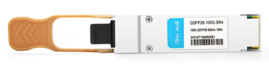
Fiber Mall 100G QSFP28 SR optical transceiver
6. How does BIDI type module achieve using only one fiber?
Usually, optical modules have two different fibers for transmitting and receiving.
Bidi (BI direction): in the same optical fiber, two optical signals with different wavelengths are used to transmit and receive optical signals in two directions respectively, and a prism is used inside the module to distinguish the optical signals in two directions. For example, like QSFP28 100G SRBD, since the laser wavelengths sent by the modules at both ends are inconsistent, pay attention to pairing when using Bidi modules.
7. What are the types and construction principles of optical fibers?
The optical fiber is a very fine white glass core, which must be covered by several layers of protective structures before use. The coated cable is an optical cable. Fiber types are divided into single-mode fiber and multimode fiber.
Differences between single-mode and multimode fibers:
1) Single mode fiber uses solid-state laser as light source, and multi-mode fiber uses light-emitting diode as light source;
2) Single mode fiber has long transmission frequency bandwidth and transmission distance, but needs laser source, which has high cost, low transmission speed, short distance and low cost of multi-mode fiber;
3) The core diameter and dispersion of single-mode fiber are small, and only one mode transmission is allowed;
4) Multimode fiber has large core diameter and dispersion, allowing hundreds of modes of transmission;
5) Multimode optical cable has a thick core and the price will be relatively expensive.
0 notes