#arduino nano project
Explore tagged Tumblr posts
Visit Tumblr Blog
Explore Tumblr blogs with no restrictions, modern design and the best experience.
Last Seen Tumblr Blogs


Fun Fact
If you dial 1-866-584-6757, you can leave an audio post for your followers.
Text
medovik
#richter ursidae#811 game#811#ryker dublin#ryker 811#811 ryker#arduino nano#arduino#arduino project#electronics#electronics hobby
20 notes
·
View notes
Text
youtube
#DIY#Arduino NANO#Load Cell#HX711 Module#Weight Measurement#Electronics Tutorial#OLED Display#Maker Project#Youtube
0 notes
Text
How to Use AHT10 High Precision Digital Temperature & Humidity Sensor with Arduino
Looking to measure temperature and humidity with high accuracy using Arduino? The AHT10 sensor is a compact, I2C-based module that provides reliable data, making it perfect for IoT projects, weather stations, and smart home automation.
What You’ll Learn: ✔️ How the AHT10 sensor works ✔️ Wiring it to an Arduino board ✔️ Writing & uploading the code to get readings ✔️ Tips for stable and accurate measurements
What You Need:
AHT10 Temperature and Humidity Sensor Module
Arduino Nano
0.96 inch SSD1306 OLED Display (128x64, I2C)
Breadboard
Connecting/Jumper Wires
Arduino Nano Cable
Download the Code & Library Arduino AHT10 Temperature and Humidity Sensor Module
Watch the full tutorial on YouTube:
youtube
Follow for more DIY electronics tutorials & Arduino projects!
3 notes
·
View notes
Text
First ATTINY85 project!
(warning: video has actual flashing LED lights)
[ Video ID: A breadboard with a Blue LED on top of an 8-pin DIP Integrated Circuit on it. The Blue LED is flashing rapidly. There are other components on the breadboard in the background. End ID ]
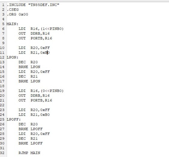
Last week I bought some ATTINY85 Microprocessors to experiment and work with :) With my W65C02 project on hold until I can afford an oscilliscope, and my Radio project delayed because I can’t quite figure out how to reverse engineer the 8 pins on the volume knob, I wanted something else to work with. I’ve been wanting to mess with Atmel microprocessors (Arduino Uno runs on an Atmel ATMEGA328), and now’s a good chance!
I’m jumping straight to assembly with the ATTINY85; I don’t know any C/C++ code, and also I’m familiar with other processor Assembly languages, so I might as well. And other than different names for functions, it’s been pretty easy so far! Something I’m not used to is that this processor, despite being pathetically tiny, has 32 registers; I’m used to working with 8 Max.
Anyways, for the code explanation: When the processor first starts, it turns on PINB0, which is physical pin 5 on the processor. Then, after counting to 256 256 times, it turns off PINB0 for another 256^256 counts. I’m away from home while writing this, so my notes arn’t here, but if I remember correctly it came up to 200k microseconds? That adds up to about 400 nano seconds per on/off cycle, or 2.5 flashes per second. I can add in another loop to make it last longer, but before I do that I’d like to look about to see if there’s a smarter way to tackle this.
My next step after this, is to figure out how to get this processor to read digital inputs: My next project is to finally do something with my box of telephone rotary dials. I already have one spec’ed out for breadboard testing. I would LOVE to show it, but Tumblr has a One Video Per Post limit :(
13 notes
·
View notes
Text
Arduino Nano Board R3 with CH340 chip

Based on the Arduino platform, the Nano R3 Board CH340 Chip without USB Cable does all the functions of the Uno, but has a smaller footprint.
Using Nano CH340 Soldered Board R3 Chip without USB cable is essential for your small project where you don’t need many pins, but the small size is very important to make it look nice.
In comparison to older versions of Arduino Nano with FTDI USB-Serial Chip, the Nano uses a low-cost USB-Serial Chip.
With the ATmega328 (Arduino Nano R3), the Nano is small, complete, and breadboard-friendly. It has more or less the same functionality as the Arduino Uno but in a different package. In addition to lacking a DC power jack, it uses a Mini-B USB cable instead of a standard one.
This device can be powered by a mini-USB cable, a 6-20V unregulated external power supply (pin 30), or a 5V regulated external power supply (pin 27).
Six PWM I/O are included from a total of 14 digital I/O, eight analog inputs, 16Mhz clock speed, and 32kB flash memory.
Please note:
The CH340 chip might not work directly with some PCs/laptops. You will need some drivers for the CH340 chip.
Arduino nano features :
TTL level serial transceiver ports (RX / TX)
Atmel Atmega328P-AU MCU used
It has a bootloader installed
Supports USB download and power supply
Provides support for external DC power supplies of 5V and 12V
2 notes
·
View notes
Text
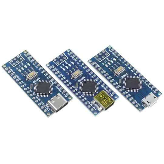
Introduction to Mini Development Board Based on Arduino Nano CH340 The Mini development board is a highly versatile microcontroller board that has gained significant popularity among makers and electronics enthusiasts. Its compact design, measuring just 45mm x 18mm, makes it particularly suitable for projects where space is at a premium. Powered by the ATmega328P microcontroller, the Nano CH340 supports various applications, from basic prototyping to complex automation tasks, thereby catering to a wide range of user needs. One of the standout features of the Mini development board is the CH340 USB-to-serial converter. This chip facilitates seamless communication between the microcontroller and a computer, allowing users to easily upload sketches and monitor serial data. Compared to its predecessors, which often utilized the FTDI chip, the CH340 offers a more cost-effective solution without compromising performance, making it a preferred choice for many hobbyists and professionals alike. Applications and Projects Using Mini Development Board for Arduino Nano CH340 The Arduino Nano CH340 is a compact yet powerful microcontroller board, making it an ideal choice for a wide array of projects. Its versatility and ease of use allow both beginners and experienced programmers to create innovative solutions across multiple domains. One common application is in robotics, where the Nano CH340 can be utilized to control motors and sensors, enabling the development of robots that can navigate environments autonomously. For those interested in home automation, the Arduino Nano CH340 serves as a reliable central unit that can manage various household devices. By integrating this board with smart sensors and relays, users can create systems that automate lighting, climate controls, and security measures. Projects can range from simple automated lighting systems to sophisticated home monitoring setups, showcasing the broad capabilities of the Nano CH340. PCB Size:43*18mm About Interface: Default shipment is type-c,if you need micro usb or mini usb interface,they are same price,just leave us message to claim the specified interface. Interested with much more quantity or other development board,contact us to talk details.View our company site to know more about our product category. Read the full article
0 notes
Text
i have a breadboard with my final project and another breadboard with my arduino nano in case i think i fucked up and killed the ultrasonic module (i haven't)
1 note
·
View note
Text
What Are the Must-Have Tools for a Future-Ready STEM Lab in Agartala?

Introduction: Why Every STEM Lab in Agartala Needs the Right Tools
A STEM Lab in Agartala is more than just a classroom—it’s a hands-on innovation center where students explore robotics, coding, AI, and engineering. To make learning engaging and future-ready, schools must equip their STEM Lab in Agartala with the right tools and technologies.
In this guide, we’ll explore the must-have tools that every future-ready STEM Lab in Agartala should have.
1. Robotics Kits – Powering Hands-On Learning
A top-quality STEM Lab in Agartala must include robotics kits to teach students about automation, AI, and engineering. Some of the best robotics kits include:
LEGO Mindstorms EV3 – Ideal for beginners, offering block-based coding. Arduino & Raspberry Pi Kits – Great for advanced robotics and IoT projects. VEX Robotics Kits – Used for competitions and real-world problem-solving.
These kits help students develop logical thinking and problem-solving skills while preparing them for careers in automation and robotics.
2. 3D Printers – Bringing Creativity to Life
A STEM Lab in Agartala should have 3D printers to help students design and prototype real-world objects. Some essential options include:
Creality Ender 3 – Affordable and beginner-friendly for schools. Ultimaker 2+ – High-quality prints for advanced projects. ️ Anycubic Photon – Best for precise, resin-based 3D printing.
With 3D printing, students can turn their ideas into reality, fostering creativity and innovation.
3. Coding & AI Learning Kits – Preparing for the Future
To make a STEM Lab in Agartala future-ready, it must include coding and AI tools for teaching programming skills. Some of the best choices are:
Scratch & Blockly – Block-based coding for beginners. Python & Java Programming Platforms – Industry-standard coding languages. Google AIY & NVIDIA Jetson Nano – AI and machine learning kits for advanced learning.
These tools help students learn AI, data science, and machine learning, making them ready for future tech careers.
4. Virtual Reality (VR) & Augmented Reality (AR) – Immersive Learning
A cutting-edge STEM Lab in Agartala should include VR and AR tools to create immersive educational experiences. The best options are:
VR and AR tools make learning more engaging and interactive, helping students visualize complex concepts easily.
5. IoT & Smart Sensors – Learning About the Connected World
An IoT-enabled STEM Lab in Agartala prepares students for the future of smart technology and automation. Essential IoT tools include:
Arduino IoT Cloud – Teaches real-world IoT applications. ESP8266 & ESP32 Microcontrollers – Used for smart device projects. Smart Sensors (Temperature, Humidity, Motion) – For creating real-time monitoring systems.
With IoT tools, students can build smart home projects, automated weather stations, and AI-driven devices.
6. Electronics & Circuit Design Kits – Understanding Engineering Basics
A future-ready STEM Lab in Agartala must include electronics kits for hands-on engineering projects. The best options are:
LittleBits Electronics Kit – Easy-to-use snap circuits for beginners. Snap Circuits Pro – Teaches circuit design in a fun way. Breadboards & Multimeters – Essential for real-world electronics projects.
Electronics kits enhance problem-solving skills and prepare students for engineering careers.
7. STEM Software & Simulations – Enhancing Digital Learning
A well-equipped STEM Lab in Agartala should also have digital tools and software for coding, engineering, and simulations. Some must-have software include:
Tinkercad – Online 3D design and electronics simulation. MATLAB & Simulink – Used for data analysis and AI applications. AutoCAD & SolidWorks – Industry-grade design software.
These digital tools help students practice real-world STEM applications in a virtual environment.
Conclusion: Build a Future-Ready STEM Lab in Agartala with the Right Tools
A high-quality STEM Lab in Agartala must include robotics kits, 3D printers, AI and coding tools, IoT kits, VR devices, and circuit design tools to prepare students for technology-driven careers.
By investing in these essential tools, schools in Agartala can create an engaging, innovative, and future-ready learning environment.
Want to set up a STEM Lab in Agartala? Contact us today to Upgrade the best solutions for your school!
0 notes
Text


fucking hate my camera
#richter ursidae#811 ryker#ryker dublin#811 game#811#arduino#arduino nano#arduino project#electronics#electronics hobby
14 notes
·
View notes
Text
How to Choose the Right Arduino Board for Your DIY Electronics

Arduino boards are at the heart of many DIY electronics projects. They are popular with hobbyists, students, and anyone who enjoys building things. If you’re new to Arduino or just unsure which board to pick for your project, this guide will help you choose the right one. With many options out there, it’s important to find the board that best fits your needs.
What is Arduino?
Before we dive into choosing a board, let’s quickly go over what an Arduino is. Arduino is an open-source platform made up of hardware and software that allows you to build electronics easily. It includes a microcontroller, which controls the board, and pins to connect sensors, motors, lights, and other parts. Many people use Arduino for prototyping, automation, and interactive projects because it’s simple to use and has a large community to help.
Things to Consider When Choosing an Arduino Board
1. How Complex is Your Project?
The complexity of your project plays a big role in choosing the best Arduino board. Some projects may need only basic functions, while others require more power or special features. Here’s a guide based on project complexity:
Simple Projects: If you’re working on basic tasks like blinking an LED, reading a temperature sensor, or turning on a light, boards like the Arduino Uno or Arduino Nano will work well. These boards are powerful enough for simple tasks.
Intermediate Projects: For projects that need to control motors, handle multiple sensors, or need more memory, you might want to choose a board like the Arduino Mega or Arduino Due. These boards have more pins and are more powerful, making them better for more complex tasks.
Advanced Projects: For projects that require lots of power, such as robotics or systems that need to process data quickly, you should look at boards like the Arduino Zero or Arduino MKR series. These boards offer more processing power and additional features for advanced projects.
2. Size and Shape of the Board
If your project has space limitations, the size of the Arduino board can be an important factor. Some projects need compact boards, while others can handle bigger ones. Here’s a look at some sizes:
Arduino Uno: It’s not the smallest, but it’s a good middle-ground between size and functionality. It’s about 68.6 x 53.4 mm.
Arduino Nano: If space is tight, the Arduino Nano is a smaller option at 45 x 18 mm. It’s great for small projects where you still need basic features.
Arduino Pro Mini: For projects that need an even smaller board, the Arduino Pro Mini is a tiny option, great for things like wearable electronics or embedded systems.
Arduino MKR Boards: The MKR series offers a good balance of size and power, especially if you need features like wireless communication for IoT projects.
3. Number of Pins and Connectivity
The number of pins on your Arduino board determines how many things you can connect to it—like sensors, motors, and other components. Simpler projects don’t need many pins, but more complicated ones will.
Arduino Uno: It has 14 digital I/O pins and 6 analog pins, which is enough for most basic projects.
Arduino Mega: If you need lots of pins, the Arduino Mega is the best choice. It offers 54 digital I/O pins, 16 analog inputs, and 4 UARTs, making it perfect for larger projects like robots or projects with multiple sensors.
Arduino Nano: The Nano has 14 digital I/O pins and 8 analog pins. It’s similar to the Uno but much smaller.
Arduino MKR Boards: These boards usually have additional connectivity options like Wi-Fi and Bluetooth, making them ideal for remote or wireless projects.
4. Power Requirements
Consider how you’ll power your project. Some boards can be powered through USB, while others may need a battery or an external power supply.
Arduino Uno: This board can be powered through USB or an external 9V battery or power supply, making it flexible for both stationary and mobile projects.
Arduino Nano: The Nano can be powered through a mini-USB connection or a 5V source. It's a great choice for small projects where power options are limited.
Arduino MKR Boards: Some MKR boards include a Li-Po battery charger, which is useful for battery-operated projects. If you want a board that can run on batteries for a long time, a MKR board might be the right choice.
5. Wireless Features
If your project needs wireless features like Wi-Fi or Bluetooth, you’ll want to choose an Arduino board that supports these functions. Many Arduino boards now come with built-in wireless capabilities, perfect for IoT (Internet of Things) projects.
Arduino MKR WiFi 1010: This board has both Wi-Fi and Bluetooth, which is great for wireless projects. It’s also compatible with the Arduino IoT Cloud, allowing you to control your devices from anywhere.
Arduino MKR GSM 1400: If you need to use mobile networks, this board has GSM/3G support, which is perfect for remote projects.
Arduino Nano 33 IoT: This board offers both Wi-Fi and Bluetooth in a small size, making it ideal for IoT projects that need compactness and wireless features.
6. Community Support
Arduino is known for its active and helpful community, which can be a big help, especially if you’re new to electronics. The most popular boards, like the Arduino Uno and Arduino Nano, have tons of tutorials, guides, and support available online. This makes it easier to get started and find solutions when you need help.
Additionally, consider looking at the availability of shields (extra boards that plug into your Arduino to add features). Popular boards often have many shields available, making it easier to expand your project without doing a lot of extra work.
7. Cost
Finally, think about your budget. While basic boards like the Arduino Uno are inexpensive, advanced boards like the Arduino Zero or MKR series can be more expensive. If you’re on a budget, you can also consider buying clone boards, which offer similar functions at a lower price.
Conclusion
Choosing the right Arduino board for your DIY electronics project depends on a few key factors, including how complex your project is, the size of the board, how many pins you need, power requirements, and whether you need wireless features. For simpler projects, the Arduino Uno or Arduino Nano should be enough. For more complex projects, consider the Arduino Mega or Arduino Due. If you need wireless communication, the Arduino MKR series is a great option.
Once you pick the right board for your needs, you’ll be ready to bring your project to life with the help of the Arduino platform. Whether you’re building a simple light control system or a robot, the right board will make your project easier and more fun to complete.
1 note
·
View note
Text
Using a Knock Sensor to Detect Knocks with Arduino!
In this project, we're interfacing the KY-031 Knock Sensor with an Arduino Nano, displaying the knock count on a 16x2 LCD with I2C, and triggering an LED for visual feedback.
🔧 What You’ll Need: ✔️ Arduino Nano ✔️ KY-031 Knock Sensor Module ✔️ 16x2 LCD with I2C Interface ✔️ LED ✔️ Jumper Wires & Breadboard
💡 How It Works: The knock sensor detects vibrations, sending a signal to the Arduino. The microcontroller then updates the LCD and blinks an LED to confirm the knock was detected. Simple but effective!
🔥 Cool Applications: 🎶 DIY Drum Pad 🚪 Secret Knock Lock 🔊 Sound-Activated Projects
Check out the full tutorial and code in the tutorial!
0 notes
Text
Arduino Projects
The open-source electronics platform Arduino is built on user-friendly hardware and software. Using the Arduino Integrated Development Environment (IDE), microcontroller boards can be programmed. Users can connect with a variety of sensors, actuators, and other electrical components thanks to the digital and analog input/output (I/O) pins on these boards.
Popular Arduino boards include:
Arduino Uno
Arduino Nano
Arduino Mega
Arduino Leonardo
Arduino MKR series
Why Choose Arduino for Your Projects?
User-Friendly: Arduino is a great option for novices due to its simplicity.
Reasonably priced: The hardware is readily accessible and reasonably priced.
Community Support: A sizable user base offers a wealth of information, forums, and tutorials.
Versatile: Works with many different types of sensors, modules, and parts.
Cross-Platform: Linux, macOS, and Windows can all use the Arduino IDE.
Tips for Successful Arduino Projects
Start Small: Take on easier tasks at first, then work your way up to more difficult ones.
Record Your Work: Make notes about your code, wiring, and troubleshooting procedures.
Learn from the Community: Seek advice and inspiration by participating in forums and online tutorials.
Try new things: Don't be scared to adjust and change projects to fit your demands.
Arduino projects are a great way to learn about programming and electronics. Your creativity is the only restriction on the range of options available, from basic LED blinkers to complex home automation systems. Arduino enables creators to realize their ideas through its user-friendly platform and extensive community support. Get an Arduino board, look through the available information, and begin creating your next fascinating project right now!
To know more, click here.
0 notes
Text
DIY Smart Health Monitoring Bracelet Using Cloudtopiaa
Introduction
Imagine having a wearable bracelet that can keep track of your vital health stats such as pulse rate, body temperature, and activity levels — perfect for fitness enthusiasts and elderly care! In this DIY project, we’ll guide you in building a Smart Health Monitoring Bracelet that collects health data and transmits it to a mobile app for real-time monitoring and alerts. By integrating Cloudtopiaa as your cloud backend, you’ll ensure secure and reliable data storage and have access to advanced analytics for long-term health monitoring.
Why build a smart Health Monitoring Bracelet with Cloudtopiaa?
Wearable health devices are growing in popularity, making it easier for people to monitor their well-being anytime, anywhere. By using Cloudtopiaa’s secure cloud services, you can store data, run analytics, and access insights from anywhere. With a cloud-backed wearable device, users can monitor their health trends over time, receive alerts when thresholds are crossed, and access a reliable data log.
Key Benefits of a Cloud-Enabled Health Monitoring Bracelet
Real-Time Health Monitoring: Track pulse rate, body temperature, and activity levels in real time.
Data Logging and Analytics: Long-term storage and analytics through Cloudtopiaa.
Remote Monitoring: Access health data securely from any location.
Expandable and Secure with Cloudtopia: Utilize Cloudtopia’s reliable and scalable services to extend functionality as needed.
Key Components and Technologies
To build your Smart Health Monitoring Bracelet, you’ll need the following components:
Microcontroller:
Arduino Nano: Compact and power-efficient, ideal for wearable projects.
ESP32: Provides Bluetooth and Wi-Fi connectivity in one chip, perfect for transmitting data to Cloudtopiaa.
Sensors:
Pulse Sensor: Measures heart rate, which can be attached to the wrist.
Temperature Sensor: Monitors body temperature.
Accelerometer (e.g., ADXL345): Tracks activity levels by measuring movements.
Bluetooth Module:
Use a Bluetooth module (such as HC-05) to transmit data from the bracelet to a mobile app. With an ESP32, you can skip an additional module, as it has built-in Bluetooth.
Mobile App:
Create a simple mobile app to display real-time health data, set alert thresholds, and track history.
Cloudtopiaa:
Use Cloudtopiaa for secure, long-term data storage and advanced data analytics, allowing remote access to data and historical tracking.
Step-by-Step Guide
Step 1: Setting Up the Hardware
Connect the Arduino Nano or ESP32:
Use the Arduino Nano for basic tracking, or ESP32 for additional Bluetooth and Wi-Fi capabilities.
Attach the Sensors:
Pulse Sensor: Connect to an analog input pin on the microcontroller. Place it on the wrist where the pulse is easily detectable.
Temperature Sensor: Attach to the bracelet where it can pick up body temperature accurately.
Accelerometer: Connect to measure movement; this sensor will help track physical activity.
Connect the Bluetooth Module (if using Arduino):
Connect an HC-05 Bluetooth module to send data to the mobile app. ESP32 users can skip this, as it has built-in Bluetooth capabilities.
Step 2: Coding the Microcontroller
Write Sensor Code:
Gather data from each sensor. Use libraries for the pulse sensor, temperature sensor, and accelerometer for ease.
Transmit Data via Bluetooth:
For Arduino Nano, set up Bluetooth communication with the mobile app.
For ESP32, use Bluetooth to transmit data directly to the app, and optionally send data via Wi-Fi to Cloudtopiaa.
Sample Code: Here’s a basic setup for reading sensor values and transmitting them:#include <Wire.h> #include <Adafruit_Sensor.h> #include <Adafruit_ADXL345_U.h>
int pulsePin = A0; // Pulse sensor on A0 int tempPin = A1; // Temperature sensor on A1 Adafruit_ADXL345_Unified accel = Adafruit_ADXL345_Unified(12345);
void setup() { Serial.begin(9600); pinMode(pulsePin, INPUT); pinMode(tempPin, INPUT); accel.begin(); }
void loop() { int pulse = analogRead(pulsePin); // Get pulse rate int temp = analogRead(tempPin); // Get temperature
sensors_event_t event; accel.getEvent(&event); // Get activity data
// Send data over Bluetooth or Wi-Fi Serial.print("Pulse: "); Serial.print(pulse); Serial.print(" Temperature: "); Serial.print(temp); Serial.print(" Acceleration: "); Serial.print(event.acceleration.x); Serial.println();
delay(1000); // Delay for next read }
Step 3: Developing the Mobile App
Set Up the Bluetooth Connection:
Use Bluetooth to display data in the mobile app in real time.
Create Real-Time Monitoring Dashboard:
Design the app to show pulse rate, temperature, and activity levels, with an option to set alert thresholds.
Integrate with Cloudtopiaa:
Set up Cloudtopiaa’s API in the app to securely log data, allowing users to view their historical health data.
Step 4: Sending Data to Cloudtopiaa for Storage and Analysis
Connect ESP32 to Wi-Fi:
For ESP32, use Wi-Fi to directly connect to Cloudtopiaa’s servers for data transmission.
Configure Cloudtopiaa:
Set up a database in Cloudtopiaa for storing health data, and create a simple API endpoint to log readings from the app.
Code Example for Sending Data to Cloudtopiaa:import requests
# Replace with your Cloudtopiaa endpoint and data url = "https://your_cloudtopiaa_api_endpoint" data = { "pulse": pulse, "temperature": temp, "activity": accel }
# Send data to Cloudtopiaa response = requests.post(url, json=data) if response.status_code == 200: print("Data sent successfully!") else: print("Failed to send data.")
Step 5: Set Up Alerts and Notifications
Cloudtopiaa Data Analysis:
Use Cloudtopiaa’s analytics to track historical trends and trigger alerts if readings exceed preset limits.
Mobile App Notifications:
Configure the mobile app to receive notifications when Cloudtopiaa detects abnormal readings in the data log, such as high pulse rates or irregular temperatures.
Step 6: Testing and Optimizing
Test for Accuracy:
Check the readings for each sensor to ensure accuracy.
Optimize Bluetooth and Wi-Fi Connection:
Adjust data transmission intervals to balance battery life and data frequency.
Additional Ideas and Expansions
Add More Health Metrics: Expand the bracelet to track additional metrics like blood oxygen levels.
Remote Access for Caregivers: Allow family members or caregivers access to health data stored on Cloudtopiaa.
Custom Dashboards on Cloudtopiaa: Use Cloudtopiaa’s data visualization tools to create a web dashboard accessible from any device.
Automated Health Reports: Set up weekly or monthly health reports generated through Cloudtopiaa’s cloud analytics.
Conclusion
You’ve successfully built a Smart Health Monitoring Bracelet with Cloudtopiaa as the cloud backbone, providing a powerful solution for real-time health monitoring. This project not only demonstrates the use of IoT and wearable technology but also shows how cloud integration can enhance health tracking, analysis, and remote monitoring.
By using Cloudtopiaa, you ensure a secure, scalable, and reliable environment for health data, making this project adaptable for larger applications, such as eldercare systems or advanced fitness tracking.
Additional Resources
Cloudtopiaa Documentation
Adafruit Sensor Libraries
Bluetooth and Wi-Fi Integration with ESP32
With Cloudtopiaa’s secure, managed cloud infrastructure, your health monitoring bracelet goes beyond a DIY project—it becomes a powerful tool for everyday health tracking, with scalable potential for future improvements.
#Tech4bizsolutions #DIYHealthTech #SmartBracelet #HealthMonitoring #Cloudtopiaa #IoTForHealth #TechDIY
0 notes
Text
Poll vote Result: Stepper Motor
Thank you all for voting on the poll, as of today I find the Stepper Motor to be the one which was the winner.
Okay so I have a few ideas, not going to poll them because I want to do the zany one first, then I'll move on to the more grounded and harder one.
Henry is a two-armed robot which will move along the ground using a set of arms connected to a servo, turning on and off with the press of a button, using a sort of crank shaft mechanism which moves both arms simultaneously.
The second is a locking mechanism which will work on a clock, which will be elaborated on in a different post.
For now, let me introduce: Henry the Crawler, this is a fairly basic idea which I plan to expand on with real blueprints later.
The idea is that I will be using an Arduino nano, connected to a breadboard which gives commands to a single stepper motor to make two arms throw itself forward.
The Single stepper motor will interact with the two arms via an axle, similar to a wind-up machine, only instead of a key there is a microcontroller and a button to turn it off and on.
Now I understand that there are issues with Henry, but I think he will be hilarious.

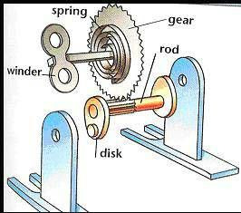
Now I thought the best way to do this would be to use the basic wind up mechanics for the actual moving parts in this robot. Doing this out of cardboard will be difficult but it seems like it is simple enough to build, just time consuming. As for the rod part I was able to ask a roommate for bamboo sticks to add onto it, so shout out to roommate for that.
As for the winder, spring and gear part of the components, I want to use one of the 28BYJ-48 5v dc stepper motors so as to make sure it is only one part which might be able to turn the beast on and off. I'll post more with the bread board and jumper wires later on.
Though not specified in the picture, I think arms with tendons in the actual moving parts might be kind of useless, and it is beyond my knowledge to be able to make them more utilized. I will likely keep the idea around for further projects.
0 notes
Text
CREWAI + OLLAMA + LLAMA3 are PROGRAMMING my ARDUINO!! | CrewAI Tutorial
Hello, tech enthusiasts! Today, we’re diving into an exciting project that combines the power of AI with the versatility of Arduino. We’ll be using CrewAI, Ollama, and Llama3 to program an Arduino board. If you’re into AI, microcontrollers, or just love tinkering with new tech, this tutorial is for you! What You’ll Need Arduino Board: Any Arduino board like Uno, Mega, or Nano will…
0 notes
Text
Controlling Multiple Relays with Arduino: A Comprehensive Guide
Introduction
Relay modules are essential components in the world of electronics, allowing you to control high-power devices with low-voltage signals. When combined with the versatility of Arduino, you can create a wide range of automated systems. In this blog post, we'll explore how to control multiple relay modules using an Arduino board.
Understanding Relay Modules
A relay module typically consists of one or more relays, each with a control pin and a pair of output terminals. By applying a low voltage (usually 5V) to the control pin, you can switch the relay, connecting or disconnecting the output terminals. This allows you to control devices that require higher voltages and currents than the Arduino can directly provide.
Required Components
Arduino board (e.g., Uno, Nano)
Relay module (2-channel or more)
Jumper wires
Breadboard (optional)
Power supply (5V DC)
Circuit Diagram
Power Supply: Connect the 5V and GND pins of the relay module to the 5V and GND pins of the Arduino, respectively.
Relay Control: Connect the control pins of the relays to digital pins on the Arduino (e.g., pins 2, 3, 4, and 5).
Arduino Code
const int relayPins[] = {2, 3, 4, 5}; // Array to store relay pin numbers
void setup() {
for (int i = 0; i < 4; i++) {
pinMode(relayPins[i], OUTPUT);
}
}
void loop() {
// Control the relays as needed
digitalWrite(relayPins[0], HIGH); // Turn relay 1 ON
digitalWrite(relayPins[1], LOW); // Turn relay 2 OFF
// ... and so on
}
Explanation
Pin Definition: An array relayPins is used to store the pin numbers connected to the relay control pins.
Setup:
pinMode(relayPins[i], OUTPUT): This line sets each pin in the array as an output pin.
Loop:
digitalWrite(relayPins[i], HIGH/LOW): This line controls the state of a specific relay by setting the corresponding pin to HIGH (ON) or LOW (OFF).
Expanding the Functionality
Sensor-Based Control: Use sensors (e.g., temperature, light, motion) to trigger relay actions based on specific conditions.
Timer-Based Control: Employ the millis() function to implement time-based switching.
Remote Control: Combine with wireless modules (e.g., Bluetooth, Wi-Fi) to control the relays remotely.
Multiple Relay Modules: Connect multiple relay modules to the Arduino to control more devices.
Safety Considerations
Voltage and Current Ratings: Ensure that the relay module's voltage and current ratings are suitable for the load you're controlling.
Heat Dissipation: If controlling high-power loads, consider using heat sinks or other cooling measures.
Proper Wiring: Double-check all connections to avoid short circuits and potential damage.
By mastering the art of controlling multiple relay modules with Arduino, you can create a wide range of innovative projects, from home automation systems to industrial control applications.
Would you like to delve deeper into a specific application or have any other questions about relay module control with Arduino?
0 notes