#bluetoothchip
Explore tagged Tumblr posts
Visit Tumblr Blog
Explore Tumblr blogs with no restrictions, modern design and the best experience.
Last Seen Tumblr Blogs


Fun Fact
Tumblr posted its first advertisements in May 2012 and subsequently earned $13M in revenue.
Text
KT1025A and Bluetooth Data Transmission: Efficient Applications of BLE and SPP
In today's interconnected world, Bluetooth technology meets not only audio transmission needs but also plays a key role in data transfer. The KT1025A chip offers excellent Bluetooth data transmission features, supporting two main modes: BLE and SPP.

BLE Transparent Transmission: A Power-Efficient Solution
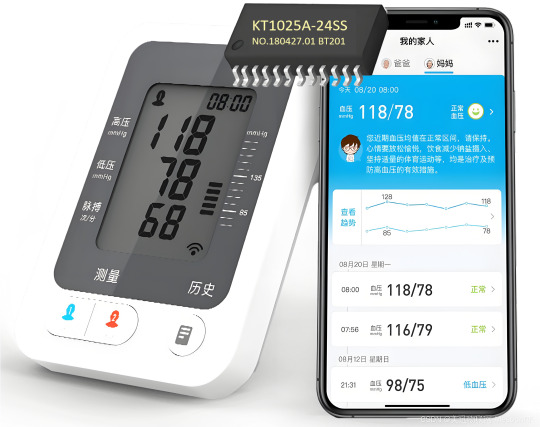
Designed for low-power applications, BLE is ideal for devices requiring long operation times with minimal power consumption. KT1025A supports standard BLE data transmission, ensuring stable connections and data interaction between devices. This makes it a top choice for smart home and health monitoring devices.
SPP Transparent Transmission: A Classic and Reliable Option
Based on the classic Bluetooth protocol, SPP provides higher data transfer rates and stability. It's perfect for applications needing fast and reliable data transmission, such as industrial control and medical data collection.
Flexibility and Reliability in Data Transmission
Whether using BLE or SPP mode, KT1025A ensures efficient and reliable data transmission. The built-in protocol stack handles the complexities of Bluetooth connections, allowing developers to focus on application development.
Practical Application Cases
In smart home systems, KT1025A can connect various sensors and controllers via BLE for seamless communication. In medical devices, SPP mode can transmit high-precision monitoring data, ensuring accuracy and timeliness.
Conclusion
With its BLE and SPP data transmission capabilities, KT1025A provides developers with flexible and powerful tools. It can meet various needs, whether for low-power BLE applications or high-stability SPP transfers, driving the development of innovative products.
3 notes
·
View notes
Video
instagram
REATEK RTL8763BFR solution case.#bluetoothboard #bluetoothheadphones #bluetoothchip #bluetoothmodule https://www.instagram.com/p/Bwx-f0kAH_s/?utm_source=ig_tumblr_share&igshid=x5tpudi60p94
0 notes
Photo

Spectra Attack Target Separation Between Wireless Communication Chips For Coordinated Attacks #bluetooth #bluetoothchip #bluetoothvulnerability #broadcom #broadcomchip #broadcomvulnerability #bug #flaw #sidechannelattack #sidechannelvulnerability #spectraattack #vulnerability #wifi #wififirmware #wifivulnerability #wirelessattacks #wirelesschip #wirelesscoexistence #wirelesscombochips #hacking #hacker #cybersecurity #hack #ethicalhacking #hacknews
0 notes
Text
Huawei presenteert Watch GT2 smartwatch met eigen chipset
Huawei presenteert Watch GT2 smartwatch met eigen chipset
Huawei heeft twee nieuwe smartwatches gepresenteerd. De Huawei Watch GT2 heeft onder de motorkap een Kirin A1-chipset met een enkele Cortex M7-processorkern, bluetoothchip en audiochip.

Huawei Watch GT2
De Watch GT2 komt in twee smaken. De grote versie met 46mm-behuizing beschikt over een 1,39-inch OLED-scherm met een resolutie van 454 bij 454 pixels. De kleine versie met 42mm-behuizing…
View On WordPress
0 notes
Text
KT6368A Bluetooth Chip at Baidu Baike
KT6368A Bluetooth Chip
Shenzhen Qingyue Electronics Co., Ltd. Product

The KT6368A chip is a pure data chip that supports Bluetooth dual mode and complies with Bluetooth 5.1. The highlights of the chip are its ultra-small size, extremely competitive price, and straightforward passthrough and UART AT control functionalities.
Chinese Name: KT148A Sound Chip
Manufacturer: Shenzhen Qingyue Electronics Co., Ltd.
I. Hardware Description

II. Description of Chip Power Consumption
Divided into two versions: KT6368A and KT6328A.
(1) The KT6368A version does not support low power consumption and is a dual-mode version. It consumes 15mA at startup and stabilizes at around 6mA afterward.
(2) The KT6328A version is a low-power version that supports only BLE.
(3) The hardware of these two chip versions is identical.
III. Description of Chip Testing

IV. Pin Description


---- Sourced from Baidu Baike
0 notes
Text
KT1025A chip
The KT1025A chip is a 4-in-1 single chip that supports Bluetooth, U-disk, and TF card playback. It adopts a 55-nanometer production process chip.The chip supports for lossless music decoding playback, along with simple and clear serial port control functions, supporting BLE transparent transmission and SPP transparent transmission capabilities.
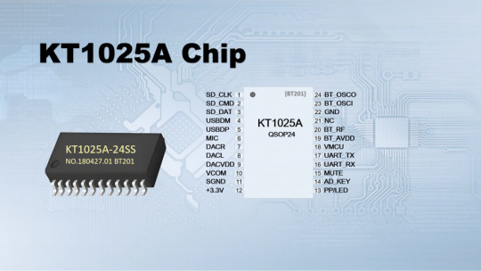
Chinese Name: KT1025A Chip
Brand: KT
Product type: Bluetooth chip
Function: Supports Bluetooth and playback via USB flash drives and TF cards
I. Introduction
The KT1025A chip is a 4-in-1 single chip that supports Bluetooth, U-disk, and TF card playback. It adopts a 55-nanometer production process chip.The chip supports for lossless music decoding playback, along with simple and clear serial port control functions, supporting BLE transparent transmission and SPP transparent transmission capabilities.
II. Function
1.General Functions
1) 16-bit Stereo DAC with headphone amplifier, SNR >= 95dB
2) Crystal-free load capacitance, chip automatically generates Bluetooth MAC address
2.Music Functions
1) Supports lossless full decoding of MP3, WAV, WMA, FLAC, AAC, APE formats
2) Supports up to 128GB U-disk and TF card, with external SPI Flash for storage.
3.Bluetooth Function Features
1) Supports Bluetooth audio transmission to connect to a phone for music playback, supports play/pause, previous/next track switching
2) Supports Bluetooth call functions, user can enable/disable, supports answer, hang up, redial, reject, and other functions
3) Bluetooth 5.0 version, supports HFP/A2DP/AVRCP/HSP/GAVDP/IOP/SPP/BLE, range about 10 meters
4) Class 2, 4dBm, frequency range 2.4G–2.480G
5) Supports BLE transparent transmission function, standalone connection to “BT201-BLE”; supports SPP transparent transmission function
III. Application Market
1.Bluetooth Audio Products e.g., Bluetooth speakers, Bluetooth headsets, car Bluetooth systems, etc.
2.Bluetooth Data Transmission Products e.g., smart door locks, car OBD diagnostics, smart carts, printers, medical device data collection.
3.Bluetooth Data Transmission + Audio Products e.g., Bluetooth music lights, Bluetooth broadcasting, electronic keyboards, and other musical instruments.
IV. Parameter Description


---- Sourced from Baidu Baike
0 notes
Text

KT1025A's UART Control: Simplifying the Development Process
In today's electronic development field, UART control is widely used for its simplicity and efficiency. The KT1025A Bluetooth audio chip integrates powerful UART control functions, significantly simplifying the development process and making it a valuable tool for developers designing Bluetooth audio products.
Detailed UART Control Functions
The KT1025A utilizes a standard AT command set, allowing developers to easily adjust functions such as volume and playback mode. Key features include:
🔹 Simple Command Format: All commands start with "AT+", parameters are in text form, and commands end with "\r\n".
🔹 Rich Functionality: Supports various operations such as volume adjustment (AT+CA), play/pause (AT+CB), and track switching (AT+CC/AT+CD).
🔹 Real-time Feedback: The chip responds to each command with either "OK" for success or error codes like "ER+1" for incorrect data frames.

Practical Application Example
In a smart home setup, sending the AT+CB command via UART can toggle the music playback state. This efficient control method saves developers significant time and effort.


Developer Experience
Some developers using the KT1025A's UART control functions have noted that its ease of use and flexibility simplify the development process and improve efficiency. They point out that this control method significantly shortens the product development cycle.
UART Debugging Assistant
The KT1025A also comes with a UART debugging assistant, facilitating function testing and troubleshooting. Using this tool, developers can easily send commands and view the chip's responses, quickly identifying and resolving issues.
Conclusion
With its robust UART control capabilities, the KT1025A reduces the development complexity of Bluetooth audio products, making it an ideal choice for developers. It offers a wide range of control options and enhances development efficiency through real-time feedback and debugging tools. For those aiming to quickly launch high-quality Bluetooth audio products, the KT1025A is undoubtedly a reliable option.

0 notes
Text
Example Explanation of the AT Command Serial Port Section for the KT1025A BT301 Bluetooth Audio Chip FM Radio Version
1. Chip Power-On Initialization
1. Upon powering on, the chip actively returns some information, but this does not include FM-related information. FM-related information will only be returned after sending a command to switch to FM mode.
2. The chip supports automatic station search, which scans the range of 87.5 MHz to 108.0 MHz to find available stations or those with good signal strength, then automatically stores them.
3. Important FM information includes three items (these exist to facilitate user display purposes):
(1) Current frequency point, i.e., a frequency between 87.5 MHz and 108.0 MHz, with a step of 0.1 MHz.
(2) Current station.
(3) Total number of stored stations.
2. Control Commands Related to the Chips FM Section
(1) After the chip enters FM mode, the user needs to send commands to trigger corresponding actions, such as automatic station search, previous station, next station, increase frequency by one step, decrease frequency by one step, etc. These are control commands.
(2) The chip automatically handles station storage and other information, so the user does not need to manage this.
AT+FC00 Start automatic station search; sending it again stops the search.
AT+FC04 Automatically search for stations downward (lower frequencies).
AT+FC01 Reserved.
AT+FC05 Automatically search for stations upward (higher frequencies).
AT+FC02 Switch to the previous station.
AT+FC06 Decrease frequency by one step (previous frequency point).
AT+FC03 Switch to the next station.
AT+FC07 Increase frequency by one step (next frequency point).
AT+FF0875 Specify FM to jump to 87.5 MHz.
AT+FF1080 Specify FM to jump to 108.0 MHz.
Query Commands Related to the Chips FM Section:
AT+PF Query the chip's current frequency point — the chip will return PF+0875 (e.g., 87.5 MHz).
AT+PC Query the station number at the current frequency point — the chip will return PC+0001 (e.g., Station 1).
AT+PT Query the total number of stations found by the chip — the chip will return PT+0012 (e.g., 12 stations).
3. Button Operation Instructions for Testing the BT301 Demo Board


For the Button Functions of FM:
1. Long-pressing the PP key initiates automatic station search. The indicator light will flash quickly, pausing briefly when a station is found, playing it for 1 second, then continuing to search for the next station.
2. FM operates in the default frequency range of 87.5 MHz to 108.0 MHz.
3. After the automatic station search is complete, you can use “Previous track” (PREV) or “Next track” (NEXT) to switch between stations.
4. Instructions for Serial Port Debugging and Testing


1. As shown in the left image above, this is the information actively returned after sending a command via the serial port to switch to FM mode:
(1) PF+0886 = Indicates the current frequency is 88.6 MHz.
(2) PC+0000 = Indicates that this frequency is not a valid station, so no station is locked.
(3) PT+0012 = Indicates the chip previously performed an automatic station search and stored 12 valid stations, i.e., 0x0C (hexadecimal for 12).
2. As shown in the right image above, this is after sending the automatic station search command via the serial port; the chip starts the automatic search and returns real-time information:
(1) Refer to the corresponding commands for specifics.
(2) To explain, the two arrows indicate: one for a station found during the search, and the other for the completion of the search.
=> For detailed debugging, use a serial debugging tool on the computer to observe the output.
0 notes
Text
Power Supply Explanation for the KT1025A BT201 Bluetooth BLE Audio Chip—Minimum, Maximum, and Most Suitable Supply Voltage
Power Supply Explanation for the KT1025A BT201 Bluetooth BLE Audio Chip—Minimum, Maximum, and Most Suitable Supply Voltage

1. Pin 18 of the module is the chip's power supply input, supporting 3.2V to 5.2V.
2. Pin 12 is the module's internal LDO output—it's an output, pay attention!!
3. For pins you don't understand, just follow the schematics we provided and copy them. About the chip's power supply and usage tips:
1. The chip is designed for “lithium battery” power scenarios, so pin 18 is named “VBAT,” meaning battery power. The chip's optimal working voltage is around 4.2V, but connecting directly to 5V is completely fine.
2. It supports a wide voltage range of 3.2V to 5.2V. Even slightly lower may work, but testing is required.
3. To support lithium battery power, the chip has a built-in 3.3V LDO to power the chip's core, so the IO operates at 3.3V levels.
4. Pin 12 is the LDO output. When the supply voltage of pin 18 exceeds 3.3V, pin 12 outputs 3.3V. If the input voltage of pin 18 is at or below 3.3V, pin 12 cannot output 3.3V and may be about 0.1V lower.
5. If you're not using an external power amplifier to drive a speaker, the chip works fine at 3.3V, even slightly lower.
6. However, if your system includes a speaker or horn, consider that sound output causes voltage fluctuations.
7. A 3.3V-powered system cannot drive large speakers, as a typical 4-ohm 3W speaker draws around 1A when producing sound, depending on the power amplifier chip.
Please consider this carefully. Important Note: Even if the USB pins are not used, it's best to bring out test points. Please pay close attention to this.
0 notes
Text
Introducing One Classic application scenarios: A Super Flexible Bluetooth Audio Transceiver Using KT1025A
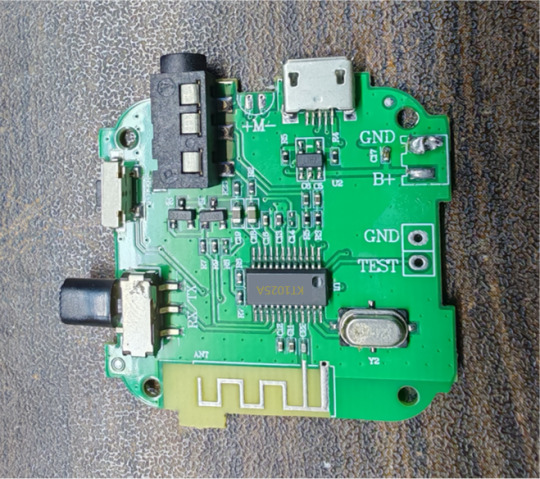
Ever wanted to build your own Bluetooth audio transmitter/receiver without dealing with bulky modules or complicated stacks? Meet my KT1025A-based Bluetooth audio board – compact, programmable, and packed with features!
What's So Cool About the KT1025A? This chip is a hidden gem for Bluetooth audio: ✔ Supports both TX (transmitter) & RX (receiver) modes – switch roles with firmware! ✔ Low-latency audio streaming – great for gaming, DIY wireless headphones, or car audio. ✔ Built-in DSP effects – bass boost, EQ, and noise suppression without extra ICs. ✔ Single-chip solution – minimal external components, perfect for compact designs.
What I Built My board includes: 🔹 USBfor firmware updates 🔹 3.5mm AUX + I2S breakout – hook up speakers, DACs, or even an ESP32 for Wi-Fi bridging. 🔹 Programmable buttons & LEDs – control playback, pairing, and mode switching. 🔹 External antenna option – better range than most consumer dongles!
Why This Rocks for Makers ✅No obscure proprietary tools – development is done via standard UART/AT commands. ✅Supports MP3, WAV, FLAC, APE format decoding– decent audio quality without licensing headaches. ✅Works out of the box as a Bluetooth receiver (e.g., for old speakers) OR a transmitter (e.g., for TVs without BT).
All schematics, a build guide are up on [Google Drive] (https://drive.google.com/drive/folders/1GNh3ebV4mieyRTAvHUEztJU4eUHxfJLR?usp=drive_link ). If you've ever wanted to turn anything into a Bluetooth audio device, this might be your easiest starting point.
Check out the pics ↓ Would love your feedback!
0 notes
Text
KT1025A Dual-Mode Bluetooth Audio Chip Layout Description and Design Precautions
1.Brief Overview
1. First, please refer to the provided BT201 test DEMO module as the standard.
2. If using the chip independently without testing the BT201 module and directly proceeding to layout, background noise is highly likely if experience is limited. Therefore, always compare with the manufacturer’s test board first.
3. The BT201 solution does not include FM functionality. Please note this. The FM circuit should be left floating without hesitation.
2.Precautions
1. Background noise or interference is common in Bluetooth audio products. Do not be careless during layout.
2. If you have not worked on audio products before, study online resources thoroughly. Assuming things casually will naturally lead to noise issues.
3. The core principle is to separate analog ground and digital ground. If unclear, consult an experienced engineer.
4. Ensure a clean power supply. Use an LDO whenever possible instead of a DC-DC converter.
5. Bluetooth operates at high-frequency RF and radiates energy, so some background noise is inevitable but can be minimized. With good design, noise is imperceptible to the human ear, though it may be measurable with instruments.
3.Antenna Description
1. For antenna and component packaging, directly refer to the PCB files of the DEMO module, available in the document library.
2. The Bluetooth antenna has no special requirements. Follow the provided package and reference instructions.
3. The Bluetooth antenna does not require impedance matching, and standard copper thickness is sufficient. Don't over complicate it—Bluetooth has a low entry barrier.
4.Power Supply Description
(1)The BT201 test board has minimal background noise, barely noticeable to the human ear.
(2)You can try powering it with a phone charger, which should not produce significant noise.
(3)Battery power is ideal as it provides pure DC and is very clean. However, consider the battery's load capacity.
(4)USB output from a desktop computer may produce significant ripple, leading to background noise. Avoid using it.
(5)If the board includes a DC-DC converter, it may cause noise. The optimal power supply is an LDO, such as a 7805.
(6)The BT201 module can drive a maximum speaker of 4 ohms, 3W with a 5V supply.
(7)When driving speakers, ensure sufficient current with a stable power supply. Insufficient current can cause speaker distortion, buzzing, etc.
(8)If possible, purchase various amplifier modules online for comparison testing. We sell Bluetooth chips, but amplifier-related noise, distortion, or other issues are extended topics that are complex and cannot be explained briefly.
5.How to check if the board has background noise?
(1)Use a clean power supply, ideally a battery, and disconnect all front-end power circuits.
(2)Connect the chip's headphone output and listen for noise. If none, check the rear-stage amplifier circuit.
(3)If USB playback has no noise but Bluetooth does, this does not necessarily indicate a problem.
(4)Use headphones to check for noise. If none, the issue lies in the amplifier section, so inspect it.
(5)If noise is present with headphones, disconnect the rear-stage amplifier and inspect the Bluetooth chip's peripheral circuits. Determine whether noise occurs during Bluetooth or MP3 playback. For Bluetooth noise, check if capacitors around the main controller are properly soldered and if they are too close to the Bluetooth module. Refer to other instructions for troubleshooting.
(6)For noise testing, avoid using a computer's USB or a charger's USB. Use a clean power supply with strong load capacity, ideally tested at 5V, not 3.7V.
6.Methods to Reduce Bluetooth Background Noise
(1)Keep the Bluetooth antenna and Bluetooth module as far as possible from analog circuits.
(2)The chip's analog ground must be connected to the power ground at the input.
(3)Check capacitors around the chip for issues such as short circuits or poor soldering.
(4)Add multiple vias to the GND of the Bluetooth section.
7.Selection and index requirements of crystal oscillators
(1)Bluetooth has high frequency offset requirements, so the crystal oscillator's quality is critical for performance. During selection, ensure consistency and stability, with a frequency deviation of ≤±10ppm and a recommended load capacitance (CL) of 12pF.
Note: Crystal-to-ground capacitors C102 = C103 = 2*CL – (4pF~6pF), where CL is the crystal's load capacitance.
(2)For designs with no size constraints, use the crystal specified in our DEMO, which is cost-effective and high-performing.
(3)For size-constrained designs, use a 24M-3225 crystal, which is slightly more expensive but performs well.
Recommendation: Use our provided crystal, which is more cost-effective and quality-assured compared to random purchases.
8.Simple PCB Layout Precautions
(1)The input voltage to LDO_IN (Pin 18 of the chip) must not exceed +5.5V.
(2)The chip must strictly separate digital GND and analog AGND (refer to the provided BT201 PCB).
(3)During PCB routing, digital GND and analog AGND must be routed separately and connected only at the battery input. If the design includes a pre-amplifier ground, connect AGND to it.
(4)All decoupling capacitors on the main controller must be placed as close as possible to the chip pins, with short ground return paths.
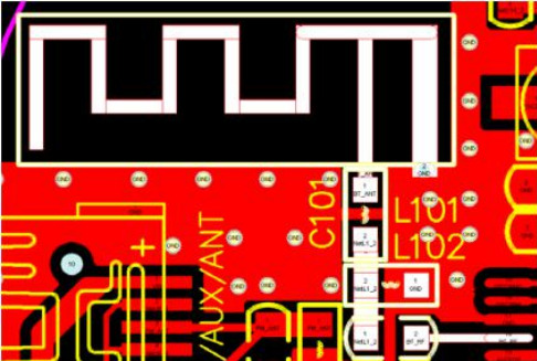
(5)Prioritize the placement of the Bluetooth antenna. The RF antenna must be near the board edge (or in an open area if structural constraints apply). The antenna matching circuit must be close to the RF pin, with short routing. The antenna's ground plane should follow the yellow outline in the antenna package, and the space on both sides should be as wide as possible, as shown in the diagram avove.
(6)The 24M crystal must be placed close to the chip's clock pins (BTOSCO and BTOSCI). Its routing must be shielded with a ground plane, kept away from interference sources, and not routed parallel to other data lines.
(7)Audio signal lines (DACL, DACR, AUXL, AUXR, MIC, etc.) must be routed away from digital signals (LCD/LED signals, USB, SD, etc.).
#bluetooth#audiochip#bluetoothchip#voicechip#ble#spp#electronic#coding#embeddeddevelopment#devlog#aiot
0 notes
Text
KT6368A Bluetooth Module: Explanation of Methods for Obtaining Bluetooth MAC Address on iOS Systems or Phones
I. Introduction
During APP development, customers often encounter issues with iOS. Therefore, we have summarized and categorized the solutions here, hoping to assist everyone. The core focus lies in the handling on the Bluetooth chip side.
Since we do not have APP development capabilities, the collected information and experience are based on communication with customers. Many of these customers' APP or mini-program developments involve our full participation, so we can provide some practical suggestions in this regard.
There are differences in obtaining the Bluetooth module's MAC address when developing APPs for Android and iOS:
1. Android systems provide an interface for obtaining the Bluetooth module's MAC address, so it can be used directly.
This includes Android-side WeChat mini-programs or other mini-programs.
2. iOS, however, is more restrictive and does not allow the retrieval of the Bluetooth module's MAC address, as it does not provide the corresponding API. Therefore, special settings must be implemented on the Bluetooth module side.
==> Method 1: Set a fixed UUID specifically for interaction with the APP. This means that after the APP connects, it can read the Bluetooth module's MAC address through this UUID.
==> Method 2: Store the Bluetooth module's MAC address in the broadcast packet, allowing iOS Bluetooth to directly obtain the MAC address during scanning.
II. Detailed Description
2.1 Method 1—Reading the MAC Address via a Specific UUID
This type of application is not common because it requires establishing a connection before obtaining the MAC address, making it impractical.
Among the many customers we have collaborated with, very few adopt this approach. The implementation is actually quite simple and easy to understand once explained.
Thus, this method is not recommended for now. Please refer to Method 2 for details.
2.2 Method 2—Storing the MAC Address in the Bluetooth Module's Broadcast Packet
Here, we reference the broadcast packet specifications of the KT6368A Bluetooth chip.
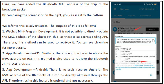
We have added the Bluetooth chip's MAC address to the broadcast packet. By comparing the screenshot on the right, the pattern can be identified.
This is referred to as "advertisData", and its purpose includes the following:
1. WeChat Mini-Program Development: There is no direct API to obtain the Bluetooth chip's MAC address, so this method can be used instead. Specific details can be found online.
2. APP Development—iOS Side: Similarly, there is no direct way to obtain the MAC address, so this method is used to retrieve the Bluetooth chip's MAC address.
3. APP Development—Android Side: This is not an issue, as the MAC address can be directly obtained via API. Therefore, whether or not this feature is used does not matter.
2.3 Method 2—Testing Procedure

1. For iOS testing, the APP used here is "BLEHelper".
2. Testing with nRF Connect is more cumbersome.
3. These two APPs are tools developed for iOS, so they use the same API interfaces. This confirms that storing the MAC address in the broadcast packet is feasible.
4. The MAC address is stored in manufacturerData, e.g., 0x724c21cb1c93.
5. Since these tool APPs can retrieve the MAC address from the broadcast packet, your own iOS APP or WeChat mini-program development should also be able to achieve this.
HCI_EIR_DATATYPE_MANUFACTURER_SPECIFIC_DATA = 0xFF
For Android testing, nRF Connect is used.
The Android side will not be elaborated further here.
III. Summary
We strongly recommend Method 2, as it perfectly resolves this issue. You can also test it with the KT6368A Bluetooth chip.
0 notes
Text
The KT1025A used in the BT201 module is a solid choice for cost-sensitive Bluetooth audio applications.
The KT1025A, used in the BT201 module, is a solid choice for cost-sensitive Bluetooth audio applications. Below is a detailed breakdown based on available information:
👉 KT1025A (BT201) Overview
✅ Bluetooth Version: Bluetooth BLE5.0 and SPP2.1
✅ Audio Features:
🔹16-bit stereo DAC for decent audio output.
🔹Supports basic codecs like MP3, WAV, FLAC, and APE formats, suitable for standard-quality audio streaming.
🔹I2S and PCM interfaces for connecting to external audio components.
🔹Supports external power amplifiers, as you've noted in your previous work with the BT201 for applications like electronic keyboards or voice toys.
✅ Control: UART interface for easy integration with microcontrollers, making it developer-friendly for embedded systems.
✅ Power Consumption: Optimized for low-power applications, ideal for battery-powered devices like toys or small IoT gadgets.
✅ Use Case: Best for budget-friendly projects requiring basic Bluetooth audio, such as smart home devices, voice-activated toys, or simple wireless speakers.

👉 Pros
✅ Cost-Effective: Affordable for mass production, aligning with your focus on cost-sensitive applications.
✅ Ease of Integration: UART control and support for external amplifiers simplify design, as seen in your BT201-based projects.
✅ Compact: The BT201 module is small, making it suitable for space-constrained designs like wearables or IoT devices.
👉 Cons
✅ Basic Features: Lacks advanced DSP or built-in noise cancellation, which may be a drawback for premium audio applications.
👉 Comparison to Alternatives
Compared to high-end chips like the Qualcomm CSR8675 or QCC5125 (recommended previously), the KT1025A is less feature-rich but significantly cheaper and easier to implement for simple audio needs. It's a better fit for the cases like smart home IoT, voice toys.
👉 Recommendation for Your Use Case
✅ Why It's Suitable: The KT1025A is a great match for your projects, its point to applications in cost-sensitive, low-to-medium complexity devices. Its support for external amplifiers and UART control aligns well with your needs for integrating with microcontrollers or audio peripherals.
✅ When to Consider Alternatives: If you're exploring higher-quality audio (e.g., for music-focused devices), consider upgrading to a chip like the Qualcomm QCC5125 for future projects.
✅ Development Tips:
🔹Leverage the I2S output for clean audio integration with external DACs or amplifiers, as you've done with the BT201.
🔹Ensure you have access to the KT1025A's datasheet or programming manual for firmware configuration.
🔹Test power consumption thoroughly if targeting battery-powered devices, as this chip is optimized for low power but may vary based on configuration.

If you need specific technical details (e.g., pinouts, firmware setup, or amplifier pairing for the KT1025A) or want to compare it further with another chip, let me know, and I can dig deeper or search for additional resources!
1 note
·
View note