#circuitMaker
Photo

PCB Design a Tiny Arduino In Altium CircuitMaker ☞ http://bit.ly/2OmNI76 #Arduino #programming
1 note
·
View note
Photo

PCB Design a Tiny Arduino In Altium CircuitMaker ☞ http://go.codetrick.net/rJlTmk2yVm #programming #code
1 note
·
View note
Photo

PCB Design a Tiny Arduino In Altium CircuitMaker ☞ http://bit.ly/2OmNI76 #Altium #Arduino
1 note
·
View note
Text
Unify Circuit Mac Download


Circuit Unify Atos
Microsoft office home and business 2016 mac free. download full. Download this app from Microsoft Store for Windows 10. See screenshots, read the latest customer reviews, and compare ratings for Circuit Overload. Circuit Design Software On Mac: There are many Circuit Design Softwares including different platforms,they are based on Windows,Linux,or On Mac, Or based on cloud servers which you could run it anywhere. Which tools you choose and on which platforms you choose to run was decided by your preferences, the functions you require the tools to have, the convenience of the tools, the. For Mac Desktop User Guide 6. Figure 6: Select Platform Dialog. Open Finder and select. Vegas pro free. On the left side of the window. Select the file named. Figure 7: Download Screen. Icon to start loading the app. Note: If a dialog box displays stating, “UC App is an. For more information on setting up the UniFi Dream Machine Pro, see UniFi - UDM: How to Set Up a Dream Machine. Host the UniFi Network Controller yourself. Alternatively, you can download and host the UniFi Network Controller yourself on a local device or a server. First, you'll need to install the controller version for your platform.
Unify Circuit For Outlook

Download Unify Software
Last week, we announced that Octopart is now powering the database behind CircuitMaker, the free PCB design tool from Altium. We’ve gotten a lot of questions about running CircuitMaker on Mac OS X, because right now, CircuitMaker runs on Windows (read about CircuitMaker’s system requirements here). However, you can run CircuitMaker if you don’t have a Windows machine: here are the steps to get CircuitMaker up and running on your Mac.Step 1: Get software to run Windows on a Mac:There are a number of options for running Windows on a Mac. In this tutorial we cover Windows 8 and 10 using VirtualBox because it is free and it allows you to switch between Windows and OS X without restarting. There are alternatives like Parallels, VMWare Fusion, and Bootcamp. Read about an in-depth comparison between Fusion 6, Parallels 11 and VirtualBox 5 if you are curious. If you only have access to Windows 7, then VMWare, Parallels or Bootcamp is the way to go, otherwise we recommend Windows 8 or 10 with VirtualBox.Download the VirtualBox for OS X:Step 2: Next, get the Windows license and installation files: None of the virtual machines include the Windows license, which you’ll need! If you already have a Windows DVD, you must create an .iso file using Disk Utility on Mac.If you already have the product keys, you can get the .iso files from the links below:Download Windows 8.1 .iso file as shown below:If you don’t have access to Windows 8.1 .iso file which is used in this tutorial, you can download Windows 7 .iso file or download Windows 10 .iso file. Also, if you don’t have a product key, you can get Windows 10 Home and Windows 10 Pro on Microsoft’s website. You can also download 90-day Trial version of Windows 8.1 Enterprise edition.Step 3: Set up a new virtual machine on VirtualBox:a) Open VirtualBox and you will see the VirtualBox Manager, where you can create a new virtual machine using the Windows .iso file you just downloaded.b) Next, you will have to decide the memory allocation for the virtual machine. It is recommended that you allocate 4GB for the virtual machine, but you should allocate the memory such that you have enough to run the host OS X. As a rule of thumb, you should not allocate more than 50% of your system RAM to the virtual machine.c) Now it’s time to set up the hard disk allocation for the virtual machine. We recommend at least 25GB.d) Choose the default setting (VirtualBox Disk Image) for the hard disk file type. Then, choose “Dynamically Allocated” or “Fixed” option for hard disk. Dynamically allocated option will only use space on your disk as it fills up (up to a maximum fixed size). Fixed size hard disk may take longer to create but is often faster to use. Using the fixed option option is recommended.e) Finally, choose the amount of hard disk space:Note: Once hard disk allocation is created, you cannot change it again after setting up the Windows machine.Congrats! Your virtual machine is now ready to run Windows.Step 4. Install Windows on your Virtual Machine:Power up the virtual machine you created by double-clicking on it. It will show the following window where you can link the .iso file you created in Step 2.The procedure will guide you through the process of installing Windows.You’ll have to put the product-key in the next step:Once your product key is accepted, the process of installation will take place.Windows is now ready to use and you can download CircuitMaker.To guide you, here are some screenshots of CircuitMaker running on a Mac using VirtualBox: Now you can run CircuitMaker on Mac OS X. Let us know if you have any questions regarding the process. We look forward to seeing your designs in the community forum!
0 notes
Text
Free Software To Open Pcb File

Printed Circuit Boards are very crucial in Electronics circuit design and making, these PCB boards are acts as support base for the Electronic Elements & components and provides bias and signal path to the required components.
Now a days growth of SMD (Surface Mount Device) and SMT (Surface Mount Technology) shrinks the electronic components size and makes more complex to the PCB design. Due to no pin hole terminals in SMD components two side of PCB board filled up with tracks and components.
Typically, free EDA software is poorly developed, or has restrictions on design size that render it useless for any real project. Not CircuitMaker - you get the full power of 16 signal + 16 plane layers, and no restrictions to the PCB dimensions. If you do not need dark current compensation you can remove the second photodiode and leave the pads open. The software reads the data using a clock which is driven by the ADC. The clock frequency is the same as the sampling rate (20MSPS). How to open PCB files. If you cannot open the PCB file on your computer - there may be several reasons. The first and most important reason (the most common) is the lack of a suitable software that supports PCB among those that are installed on your device. A very simple way to solve this problem is to find and download the appropriate application.
The Printed Circuit Board have copper tracks to connect the electronic components placed upon it, Different types of PCBs are,
Single Sided PCBs
Double Sided PCBs
Multilayer PCBs
Rigid PCBs
Flex PCBs
Rigid-Flex PCBs
In order to produce compact, quality perfect printed circuit board we need good PCB design software, this Article may help you to find most leading and competitive 10+ free PCB design software.
eSim
Kicad
gEDA
Free PCB
Osmond PCB
ExpressPCB
PCBWeb Designer
DesignSpark PCB
Fritzing
Eagle
ZenitPCB
eSim
eSim (previously known as Oscad / FreeEDA) is an open source EDA tool for circuit design, simulation, analysis and PCB design. eSim offers similar capabilities and ease of use as any equivalent proprietary software for schematic creation, simulation and PCB design, without having to pay a huge amount of money to procure licenses. This software runs on Ubuntu Linux and Windows and it is released under GPL (eSim Software).
Kicad
Kicad EDA is a cross platform and open source electronics Design Automation suite. It enables support for every aspects in electronics design such as, Schematic capture, PCB layout and 3D Viewer,it allow you to modify the aesthetic appearance of the board or to hide and show features for easier inspection (Kicad software).
gEDA
PCB design software from gEDA is a cross platform software, and has rats nest features, schematic/netlist import, design rule checking and provide Industry standard RS-274X (Gerber), photorealistic design review images and lot more..(gEDA PCB software).
Free PCB
FreePCB is a free, open-source PCB editor for Microsoft Windows, released under the GNU General Public License. It was designed to be easy to learn and easy to use, yet capable of professional-quality work.
1 to 16 copper layers
Board size up to 60 inches by 60 inches
Imports and exports PADS-PCB netlists
Exports extended Gerber files (RS274X) and Excellon drill files
Design rule checker
Autosave
These are notable features built in Freepcb PCB design software. (freepcb Software)
Osmond PCB
Osmond PCB provides free software for small designs, it has multiple layer design option, we can design thru-hole and surface mount based PCBs. It has Design rule checking features and produce industrial standard boards output (Osmond PCB Software).
ExpressPCB
ExpressPCB software is a user friendly easy to use PCB design software, First time PCB designer can easily operate this software without any struggle and it provides well explained documentation & steps on how to make printed circuit board (ExpressPCB software).
PCBWeb Designer
PCBweb is a free CAD application to designing and manufacturing electronics hardware, It provides full service design and manufacturing features, we can do schematic capture fast using easy to use writing tool, we can create multi-layer boards and it has integrated Arrow part library (PCBweb designer)
DesignSpark PCB
DesignSpark PCB software from RS components and Allied Electronics makes it easy to design complex PCBs and this software works with minimum configuration systems, It has huge library collections and good support by forum and video tutorials (DesignSpark PCB).
Fritzing
Fritzing is an open-source hardware initiative that makes electronics accessible as a creative material for anyone. We offer a software tool, a community website and services in the spirit of Processing and Arduino, fostering a creative ecosystem that allows users to document their prototypes, share them with others, teachelectronics in a classroom, and layout and manufacture professional pcbs… from its website (Fritzing software).
Eagle
Autodesk eagle PCB design software is powerful and easy to use tools for every engineer, and it is offered in free version and also paid version , it has easy to use schematic editor, powerful pcb layout and ready to use part libraries and this software most suitable for complex pcb designs (eagle software).
ZenitPCB
Zenit PCB software is a excellent tool to create professional printed circuit board, and it is easy to use CAD proram, ZenitPCB Suite is directed to all those people who want to make printed circuit board for hobby, or to student and academics from universities or high schools, who want to create their own pcb with a professional approach and particularly without having to pay for expensive licenses, from its website (ZenitPCB software).
Note: This Article is just to show you the software options for PCB designing and there is no compulsion or promoting of any software and Images used here are for the education purpose only, Image credit to the respective owners.
ProntoCAD-CONNECT is the importer engine featured in all Unisoft software modules and allows the importing of virtually any CAD, Gerber, Bill of Materials (BOM), CNC and mechanical drawing formats.
VIDEO: Click the video above for product overview.
BOM IMPORTING
SOFTWARE DOWNLOAD: A quick way to learn about the software is to download it by clicking this link.
The software has HELP for most menu items by hovering over the menu item for a second then click any of the videos, manual or website links to learn about the software. For example the SMART OPEN menu has help on importing CAD and Gerber files.

Free PCB CAD Viewer &
Gerber Viewer Software
The software download link and periodic updates will be sent to this address.
Please double check that your email address is correct. Your email address will be kept private.
Importing Your CAD Files
Importing your CAD files is easy with the Unisoft software! The 'SMART OPEN' feature is your CAD EXPERT that does all the work for you finding and sorting out all the proper files in your project folder!
TO USE 'SMART OPEN': From the Unisoft software click FILE from the main menu, click SMART OPEN and a new window opens. In the new window browse to and select the directory that your project CAD or Gerber files are located in. A new window opens and select one of the files presented and your PC Board will be displayed.
The SMART OPEN feature looks at all the files for your project in the folder you select and then presents you with only the correct PC Board, CAD and Gerber files that can be imported into the Unisoft software with the most desirable CAD files at the top of the list.
MORE ABOUT CAD FILE IMPORTING:
The Unisoft software can import the wide assortment of CAD, Gerber, BOM and XY rotation files that EMS/CEM and OEM electronic manufactures encounter. Unisoft has a set of the best ECAD, Gerber and BOM importers in the world today. This software developed over the last 30 years imports all types of ECAD, MCAD and BOM formats.
Unisoft imports the ASCII text files created by CAD systems and supports revision levels dating back to the 1980's and this can be important because older versions of CAD systems are still in use and need to be supported. For example the PADS ASCII output .ASC file format dates back to the 1980's and Unisoft supports virtually all the variations PADS created through the years within that format.
Unisoft SMART OPEN feature outlined previously above, will scan all files in a folder and will automatically detect the CAD files which have correct content for importing into the Unisoft software. So for example if you have a folder containing 40 assorted CAD, Gerber, BOM and Drawing files for a PC Board project use the Unisoft SMART OPEN feature by clicking FILE from the main menu then click SMART OPEN and point to the directory folder with the files and click OK and you will be presented with a list of the CAD files you can import. In general look for at a minimum 'PCB pin x-y' in the field 'Contains this type of data'. If the file contains 'PCB pin x-y' data then usually with the Unisoft software this will be sufficient data to program your Assembly, AOI inspection and selective Soldering equipment; and also create process assembly sheets, kitting labels, costing reports, do first article and general inspection.
If you are having trouble finding the right type of CAD file to import into the Unisoft software then the table below lists PC Board CAD, Gerber and mechanical CAD file formats that maybe imported into the Unisoft software. You can use this table to match up the correct CAD file required to be imported. After you have installed the Unisoft software full samples of most of the CAD formats listed in the table below can be found by default in the directory c:program filesunisoftcad-import-file-samples-etc or c:program files(x86)unisoftcad-import-file-samples-etc . In that directory the sample files start with SAMPLE_ and the CAD System is in the name of the file, for example the file SAMPLE_PADS.ASC is a full sample of the PADS CAD system ASCII file. If you are having trouble finding the right type of CAD file then use these samples to match them to the CAD files your CAD department or your clients may have available for processing with the Unisoft software. For example if your company or client uses the OrCAD CAD system to design their PC Boards and they have not sent you the correct files then use the table below to have them send you the desired files. From the table below under the field 'CAD system' look for OrCAD and you will find two listings. Next under the field 'File label or type' you will find 'Min File' and 'GENCAD'. Under the field 'Contains this type of data' you will find that both have the same listing of 'PCB pin x-y,netlist,trace data'. The field 'Contains this type of data' indicates the PC Board data types contained in the file and usually the more types listed the better. In the case of OrCAD both the 'Min File' and 'GENCAD' files have full 'Contains this type of data' listings of 'PCB pin x-y,netlist,trace data' and either one will work fine for importing into the Unisoft software. Next look at the field 'Standard extension' and in the case of OrCAD they are .MIN and .CAD and if you have either of these files available you are ready to go; if not then request them from your client or your CAD department and do this by forwarding them the samples of the file formats you need and these samples are available by default in the directory c:program filesunisoftcad-import-file-samples-etc or c:program files(x86)unisoftcad-import-file-samples-etc . In the case of OrCAD the two files you would send them would be sample_orcad.min and sample_GENCAD.cad and these files should aid them in matching the correct file type you need.
STANDARD CAD FILES: Note that many CAD systems in addition to exporting their native format may export industry standard CAD formats such as GENCAD, GENCAM, FABMASTER, IPC-D-356, IPC-2581, etc. In most cases these files can be used in place of the native CAD files and are importable into the Unisoft software.
GERBER FILES: When CAD files are not available then Gerber files are often the only files available to Contract Manufacturers and OEM's. The Unisoft software can quickly translate these files into your required manufacturing files (see note 2 below).
X/Y CENTER & ROTATION FILES: When CAD files are not available then X/Y center & rotation files are often the only files available to Contract Manufacturers and OEM's. The Unisoft software can quickly translate these files into your required manufacturing files (see note 7 below).
CAD & Gerber File Listings
The information below helps to find the best data files for importing to the Unisoft software.
We are available anytime to assist you directly online.
CAD system or standards fileFile label or typeStandard extensionContains this type of data / rotation typeSampleAccel P-CAD (see note 12)PDIF.pdf (see note 12)PCB pin x-y,netlist,trace (see note 12 / 1a)yAccel P-CAD (see note 18)IPC-D-356.ipc/.356/varies (see note 18)PCB pin x-y,netlist (see note 18 / 1a)yAccel P-CAD (see note 13)ASCII output.PCB (see note 13)PCB pin x-y,netlist,trace (see note 13 / 1a)yAccel P-CAD (see note 2)
Altium Designer(see note 5)Gerber
Protel outputvaries (see note 2)
.pro (see note 5)PCB drawing file (see note 2 / 1a)
PCB pin x-y,netlist,trace (see note 5 / 1a)y
yAltium Designer (see note 21)
Altium Designer (see note 22)
Altium Designer (see note 5)ODB++
IPC-2581
pin x-y listvaries
.cvg
.PCB (see note 5)PCB pin x-y,netlist,trace (see note 21 / 1b)
PCB pin x-y,netlist,trace (see note 22 / 1b)
PCB pin x-y,netlist,trace (see note 5 / 1a)y
y
yAltium Designer (see note 5)
Altium Designer (see note 2)Data
Gerber.PCBdoc (see note 5)
varies (see note 2)PCB pin x-y,netlist,trace (see note 5 / 1a)
PCB drawing file (see note 2 / 1a)n
yAutoCAD (see note 20 below)Design Exchange.dxf (see note 20)drawing file (see note 20)yAutodesk Eagle (see Eagle PCB)
AutoCAD Electrical (see note 31)
AutoTRAX DEX (see note 19)
AutoTRAX DEX (see note 2)
Bartels Auto Engineer(note 18)(see Eagle PCB)
x-y centroid
(see note 19)
Gerber
IPC-D-356(see Eagle PCB)
varies (see note 31)
(see note 19)
varies (see note 2)
.ipc/.356/varies (see note 18)(see Eagle PCB)
PCB x-y center (see note 31)
(see note 19)
PCB drawing file (see note 2 / 1a)
PCB pin x-y,netlist (see note 18 / 1a)-
y
n
y
yBartels Auto Engineer GENCAD.cadPCB pin x-y,netlist,trace (see note 1b)y Bartels Auto Engineer (note 2)
Cadence-Valid Allegro(note 3)Gerber
pin x-y listvaries (see note 2)
varies (see note 3)PCB drawing file (see note 2 / 1a)
PCB pin x-y,netlist,trace (see note 3 / 1b)y
yCadence-Valid Allegro (note 3)
Cadence-Valid Allegro (note 2)IPC-D-356
Gerber.ipc/.356 (see note 3)
varies (see note 2)PCB pin x-y,netlist (see note 3 / 1a)
PCB drawing file (see note 2 / 1a)y
yCADint
CADint (note 18)
CADint (see note 26)
CADint (note 2)
CADSTAR (see note 17 below)GENCAD
IPC-D-356
pin x-y list
Gerber
CADIF.cad
.ipc/.356/varies (see note 18)
.fat/.fatf - FATF file (note 26)
varies (see note 2)
.paf (see note 17)PCB pin x-y,netlist,trace (see note 1b)
PCB pin x-y,netlist (see note 18 / 1a)
PCB pin x-y,netlist,trace (see note 26 / 1b)
PCB drawing file (see note 2 / 1a)
PCB pin x-y,netlist,trace (see note 1a)y
y
y
y
yCADSTAR
CADSTAR (see note 2)pin x-y list
Gerber.cdi
varies (see note 2)PCB pin x-y,netlist,trace (see note 1a)
PCB drawing file (see note 2 / 1a)y
yCIRCADGENCAD.cadPCB pin x-y,netlist,trace (see note 1b)yCIRCAD (see note 4 below)
CIRCAD (see note 2)IPC-D-356
Gerber.ipc/.356 (see note 4)
varies (see note 2)PCB pin x-y,netlist (see note 4 / 1a)
PCB drawing file (see note 2 / 1a)y
yComputerVision
ComputerVision (see note 2)pin x-y list
Gerber.cvi
varies (see note 2)PCB pin x-y,netlist,trace
PCB drawing file (see note 2 / 1a)n
yCopper Connection (see note 2)
CR5000 (see note 17 below)
CR5000 (see note 6 below)
CR5000 (see note 2)
CR8000 (see note 17 below)
CR8000 (see note 6 below)
CR8000 (see note 2)
DesignSpark (see note 27)
DesignSpark (see note 2)
Diptrace
Diptrace
Diptrace
Diptrace
Diptrace
Diptrace (see note 7)
Diptrace (see note 2)
Douglas CAD/CAM Pro(note 7)
Douglas CAD/CAM Pro (note 2)
Draftview(see note 23 below)
Draftware(see note 23 below)
Eagle PCB(see note 4 below)Gerber
CADIF
ODB++
Gerber
CADIF
ODB++
Gerber
ODB++
Gerber
IPC-D-356
ODB++
PADS type ASCII
PCAD PCB
Min OrCAD file
x-y centroid
Gerber
x-y centroid
Gerber
drawing file
drawing file
IPC-D-356varies (see note 2)
.paf (see note 17)
varies (see note 6)
varies (see note 2)
.paf (see note 17)
varies (see note 6)
varies (see note 2)
varies (see note 27)
varies (see note 2)
.ipc/.356
varies (see note 6)
.asc
.pcb
.min
varies (see note 7)
varies (see note 2)
varies (see note 7)
varies (see note 2)
varies (see note 23)
varies (see note 23)
.ipc/.356 (see note 4)PCB drawing file (see note 2 / 1a)
PCB pin x-y,netlist,trace (see note 17 / 1a)
PCB pin x-y,netlist,trace (see note 6 / 1b)
PCB drawing file (see note 2 / 1a)
PCB pin x-y,netlist,trace (see note 17 / 1a)
PCB pin x-y,netlist,trace (see note 6 / 1b)
PCB drawing file (see note 2 / 1a)
PCB pin x-y,netlist,trace (see note 6 / 1b)
PCB drawing file (see note 2 / 1a)
PCB pin x-y,netlist,trace (see note 6 / 1b)
PCB pin x-y,netlist,trace
PCB pin x-y,netlist,trace (see note 1a)
PCB pin x-y,netlist,trace
PCB pin x-y,netlist,trace (see note 1a)
PCB x-y center (see note 7)
PCB drawing file (see note 2 / 1a)
PCB x-y center (see note 7)
PCB drawing file (see note 2 / 1a)
drawing file
drawing file
PCB pin x-y,netlist (see note 4 / 1a)y
y
y
y
y
y
y
y
y
y
y
y
y
y
y
y
y
y
y
y
yEagle PCB (see note 4 below)GENCAD.cad (see note 4)PCB pin x-y,netlist,trace (see note 4 / 1b)yEagle PCB (see note 4 below)pin x-y list.fatf - FATF file (see note 4)PCB pin x-y,netlist,trace (see note 4 / 1b)yEagle PCB (see note 4 below)
Eagle PCB (see note 2)
Easy-PC(see note 8 below)
Easy-PC (see note 32 below)
Easy-PC (see note 2)other
Gerber
GENCAD
ODB++
Gerberscripts (see note 4)
varies (see note 2)
cad (see note 8)
varies (see note 32)
varies (see note 2)PCB exports using scripts (see note 4)
PCB drawing file (see note 2 / 1a)
PCB pin x-y,netlist,trace (see note 21 / 1b)
PCB pin x-y,netlist,trace (see note 32 / 1b)
PCB drawing file (see note 2 / 1a)y
y
y
y
yEasyEDA
EasyEDA
EasyEDA
EasyEDA
EE Designer
EE Designer (see note 2)PADS-PCB
Protel output
x-y centroid
Gerber
ASCII output
Gerber.asc
.pro
varies (see note 7)
varies (see note 2)
.ala
varies (see note 2)PCB pin x-y,netlist,trace (see note 1a)
PCB pin x-y,netlist,trace (see note 1a)
PCB x-y center (see note 7)
PCB drawing file (see note 2 / 1a)
PCB Ascii
PCB drawing file (see note 2 / 1a)y
y
y
y
n
yFabmaster (see note 26)pin x-y list.fatf - FATF file (note 26)PCB pin x-y,netlist,trace (see note 26 / 1b)yFabmaster
Fabmaster (see note 2)pin x-y list
Gerbervaries
varies (see note 2)PCB pin x-y,netlist,trace (see note 1b)
PCB drawing file (see note 2 / 1a)y
yFastCAD (see note 2 below)Gerbervaries (see note 2)PCB drawing file (see note 2 / 1a)yFreePCB (see note 2 below)
FreePCB
Fuji PCB assembly file
GENA PxxxPCB(see note 7 below)
GENA PxxxPCB (see note 2)Gerber
PADS-PCB
Flexa .pgo
x-y centroid
Gerbervaries (see note 2)
.asc
.pgo
varies (see note 7)
varies (see note 2)PCB drawing file (see note 2 / 1a)
PCB netlist (pin x-y?, trace?)
PCB x-y center
PCB x-y center (see note 7)
PCB drawing file (see note 2 / 1a)y
y
y
y
yGENCADGENCAD.cadPCB pin x-y,netlist,trace (see note 1b)yGENCAMGENCAM.gcmPCB pin x-y,netlist,traceyGerber (see note 2 below)Gerbervaries (see note 2)PCB drawing file (see note 2 / 1a)yHPGL (see note 23 below)Internet.hpgdrawing fileyIncases
Incases (see note 2)TL CAD
Gerber.tl
varies (see note 2)PCB Ascii
PCB drawing file (see note 2 / 1a)n
yIntergraph
Intergraph (see note 2)
pin x-y list
Gerber.lst
varies (see note 2)PCB pin x-y,netlist,trace
PCB drawing file (see note 2 / 1a)y
yIPC-2581 (see note 24)
IPC-2581A(xml) (see note 25)
IPC-D-356(see note 18)IPC-2581
IPC-2581A
IPC-D-356.cvg (see note 24)
.xml (see note 25)
varies (see note 18)PCB pin x-y,netlist,trace (see note 24 / 1b)
PCB pin x-y,netlist,trace (see note 25 / 1b)
PCB pin x-y,netlist (see note 18 / 1a)y
y
yKeysight ADS (see note 7)
Keysight ADS (see note 2)
KiCAD
KiCAD (see note 7)
KiCAD (see note 2)
x-y centroid
Gerber
GENCAD
x-y centroid
Gerbervaries (see note 7)
varies (see note 2)
cad
varies (see note 7)
varies (see note 2)PCB x-y center (see note 7)
PCB drawing file (see note 2 / 1a)
PCB pin x-y,netlist,trace (see note 1b)
PCB x-y center (see note 7)
PCB drawing file (see note 2 / 1a)y
y
y
y
yMcCADIPC-D-356.ipc/.356PCB pin x-y,netlist (see note 1a)yMcCADGENCAD.cadPCB pin x-y,netlist,trace (see note 1b)yMcCAD
McCAD (see note 2)
pin x-y list
Gerber.tbs
varies (see note 2)PCB pin x-y,netlist,trace
PCB drawing file (see note 2 / 1a)n
yMentorBoardStation (see note 29)Mentor Neutral pin x-y.neu/variesPCB pin x-y,netlist (see note 1a)yMentorBoardStationMentor Route (traces).txt/variesPCB traceyMentorBoardStation (note 6)
MentorBoardStaion (note 2)ODB++
Gerbervaries (see note 6)
varies (see note 2)PCB pin x-y,netlist,trace (see note 6 / 1b)
PCB drawing file (see note 2 / 1a)y
yMentor Expedition (see note 9)GENCAD.cad (see note 9)PCB pin x-y,netlist,trace (see note 9 / 1b)yMentor Expedition (see note 9)IPC-D-356.ipc/.356 (see note 9)PCB pin x-y,netlist (see note 9 / 1a)yMentor Expedition (notes 6, 9)
Mentor Expedition (see note 2)ODB++
Gerbervaries (see notes 6, 9)
varies (see note 2)PCB pin x-y,netlist,trace (notes 6, 9 / 1b)
PCB drawing file (see note 2 / 1a)y
yODB++ (see note 6 below)pin x-y listvaries (see note 6)PCB pin x-y,netlist,trace (see note 6 / 1b)yOrCAD PCB Designer (note 30)
OrCAD PCB Designer (note 6)
OrCAD PCB Designer (note 28)
OrCAD PCB Designer (note 2)
OrCAD MasstekGENCAD
ODB++
IPC-2581
Gerber
Min file.cad
varies (see note 6)
.cvg
varies (see note 2)
.minPCB pin x-y,netlist,trace (see note 1b)
PCB pin x-y,netlist,trace (see note 6 / 1b)
PCB pin x-y,netlist,trace (see note 22 / 1b)
PCB drawing file (see note 2 / 1a)
PCB pin x-y,netlist,trace (see note 1a)y
y
y
y
yOrCAD Masstek
OrCAD Masstek (note 18)
OrCAD Masstek (see note 2)
GENCAD
IPC-D-356
Gerber.cad
.ipc/.356/varies (see note 18)
varies (see note 2)PCB pin x-y,netlist,trace (see note 1b)
PCB pin x-y,netlist (see note 18 / 1a)
PCB drawing file (see note 2 / 1a)y
y
y
OrCAD 386+ (see note 7)
OrCAD 386+ (see note 2)x-y centroid
Gerbervaries (see note 7)
varies (see note 2)PCB x-y center (see note 7)
PCB drawing file (see note 2 / 1a)y
yPADS (see note 11 below)ASCII output.asc (see note 11)PCB pin x-y,netlist,trace (see note 11 / 1a)yPADS (see note 6 below)
PADS (see note 2)ODB++
Gerbervaries (see note 6)
varies (see note 2)PCB pin x-y,netlist,trace (see note 6 / 1b)
PCB drawing file (see note 2 / 1a)y
yPanasonic PCB assembly file
Pantheon/Intercept
Pantheon/Intercept (note 2)
Pantheon/Intercept (note 18)
Pantheon/Intercept
Pantheon/Intercept (note 6)
Pantheon/Intercept
P-CAD(see note 12 below)Panasonic .crb
GENCAD
Gerber
IPC-D-356
Mentor
ODB++
Visual
PDIF.crb
.cad
varies (see note 2)
.ipc/.356/varies (see note 18)
.neu
varies (see note 6)
varies
.pdf (see note 12)PCB x-y center
PCB pin x-y,netlist,trace (see note 1b)
PCB drawing file (see note 2 / 1a)
PCB pin x-y,netlist (see note 18 / 1a)
PCB pin x-y,netlist (see note 1a)
PCB pin x-y,netlist,trace (see note 6 / 1b)
PCB pin x-y,netlist,trace
PCB pin x-y,netlist,trace (see note 12 / 1a)n
y
y
y
y
y
y
yP-CAD (see note 18 below)IPC-D-356.ipc/.356/varies (see note 18)PCB pin x-y,netlist (see note 18 / 1a)yP-CAD (see note 13 below)
P-CAD (see note 2)ASCII output
Gerber.PCB (see note 13)
varies (see note 2)PCB pin x-y,netlist,trace (see note 13 / 1a)
PCB drawing file (see note 2 / 1a)y
yPulsonix
Pulsonix (note 33)
Pulsonix (see note 2)GENCAD
ODB++
Gerber.cad
varies (see note 33)
varies (see note 2)PCB pin x-y,netlist,trace (see note 1b)
PCB pin x-y,netlist,trace (see note 33 / 1b)
PCB drawing file (see note 2 / 1a)y
y
yProtel (see note 14 below)Protel output.PCB/.pro (see note 14)PCB pin x-y,netlist,trace (see note 14 / 1a)yProtel (see note 18 below)
Protel (see note 2)Protel output
Gerber.ipc/.356/varies (see note 18)
varies (see note 2)PCB pin x-y,netlist (see note 18 / 1a)
PCB drawing file (see note 2 / 1a)y
yProteus (see note 6 below)
Proteus (see note 2)
SCI Card
SCI Card (see note 2)ODB++
Gerber
Neutral file
Gerbervaries (see note 6)
varies (see note 2)
.cii
varies (see note 2)PCB pin x-y,netlist,trace (see note 6 / 1b)
PCB drawing file (see note 2 / 1a)
PCB Ascii (see note 1a)
PCB drawing file (see note 2 / 1a)y
y
n
ySeetrax Ranger
Seetrax Ranger (see note 2)GENCAD
Gerber.cad
varies (see note 2)PCB pin x-y,netlist,trace (see note 1b)
PCB drawing file (see note 2 / 1a)y
ySuperMax ECAD (see note 18)
SuperMax ECAD (see note 2)IPC-D-356 Netlist
Gerber.ipc/.356/varies (see note 18)
varies (see note 2)PCB pin x-y,netlist (see note 18 / 1a)
PCB drawing file (see note 2 / 1a)y
yTango (Protel) (see note 15)
Tango (Protel) (see note 2)pin x-y list
Gerber.PCB (see note 15)
varies (see note 2)PCB pin x-y,netlist,trace (see note 15 / 1a)
PCB drawing file (see note 2 / 1a)y
yTheda
Theda (see note 2)TL
Gerber.tl
varies (see note 2)PCB pin x-y,netlist
PCB drawing file (see note 2 / 1a)n
yULTIboard (see note 16 below)GENCAD.cad (see note 16)PCB pin x-y,netlist,trace (see note 16 / 1b)yULTIboard (see note 18 below)
ULTIboard (see note 2)IPC-D-356 Netlist
Gerber.ipc/.356/varies (see note 18)
varies (see note 2)PCB pin x-y,netlist (see note 18 / 1a)
PCB drawing file (see note 2 / 1a)y
yVeribestpin x-y list.vrbPCB pin x-y,netlistyVeribest (see note 10 below)
Veribest (see note 2)
Valor (see note 6 below)GENCAD
Gerber
ODB++.cad (see note 10)
varies (see note 2)
varies (see note 6)PCB pin x-y,netlist,trace (see note 10 / 1b)
PCB drawing file (see note 2 / 1a)
PCB pin x-y,netlist,trace (see note 6 / 1b)y
y
yVisula (see note 17 below)
Visula (see note 2)CADIF
Gerber.paf (see note 17)
varies (see note 2)PCB pin x-y,netlist,trace (see note 17 / 1a)
PCB drawing file (see note 2 / 1a)y
yVutrax (see note 2)
X-Y Component Center (note 7)Gerber
X-Y centersvaries (see note 2)
.xyr (see note 7)PCB drawing file (see note 2 / 1a)
PCB X-Y Components centers (see note 7)y
yZuken (see note 17 below)
Zuken(see note 6 below)
Zuken (see note 2)CADIF
ODB++
Gerber.paf (see note 17)
varies (see note 6)
varies (see note 2)PCB pin x-y,netlist,trace (see note 17 / 1a)
PCB pin x-y,netlist,trace (see note 6 / 1b)
PCB drawing file (see note 2 / 1a)y
y
y
The CAD and Gerber file listings above are provided for informational purposes only. Unisoft is not responsible for any problems encountered with the usage of this information.
Full samples of most of the CAD formats in the table above can be downloaded by clicking this link https://www.unisoft-cim.com/download/cad_samples.zip. After the download is complete you will find the CAD samples in the file CAD_SAMPLES.ZIP.
BINARY FILES: The Unisoft software imports the ASCII files the ECAD systems export but it does not import their binary files. Binary PCB database files are the ECAD companies own proprietary binary format. These binary file formats are normally not public or documented and my violate copyrights. Also as an ECAD company releases new versions of it's software their binary format may change and it would be virtually impossible to modify the Unisoft software to accommodate these changes in a timely manner. For these reasons the Unisoft software does not import the binary files directly and only imports the standard ASCII files these ECAD systems export. TIP: If you try to open your CAD file with a TEXT editor and the characters are not standard ASCII text characters then it is most likely a binary file and not the ASCII CAD file and the Unisoft software will not be able to import it!
Note 1a:CAD files without explicitly defined component rotations: This CAD file does not have explicitly defined component rotations.
This CAD file has component pin information but no usable data about component rotations and in these cases Unisoft automatically calculates component rotations using standard zero degree package orientations.
Note 1b:CAD files with explicitly defined component rotations: This CAD file has explicitly defined component rotations.
This CAD file contains rotation information. When a CAD file is imported into the Unisoft software were the component rotations are explicitly defined in the CAD file then Unisoft assigns these explicitly defined rotations to the components.
In some cases it may be desirable to modify these explicilty defined component rotations. If this is the case then the RESET ROTATION feature can be used to change the rotation of the component package shapes in CAD files that have explicitly defined rotations. When the RESET ROTATION feature is used then the Unisoft software automatically calculates component rotations using standard zero degree package orientations.
Note 2:Gerber: Gerber data is basically a drawing file of the PC Boards pad information. Most of the systems listed above gerber data files. Gerber does not contain component, pin or netlist information. Wherever possible, from the table above, try to obtain CAD files with pin x-y,netlist,trace data. However as is the case with virtually all Contract Electronics Manufacturers [EMS/CEM] often the only data their clients provide are the gerber files. In this case the Unisoft GERBER-CONNECTION menu is used to quickly turn these raw Gerber files into intelligent data to program your Assembly, AOI inspection, ATE Test and selective Soldering equipment; and also create process assembly sheets, kitting labels, costing reports, do first article and general inspection.
Gerber files are exported by hundreds of different CAD and software systems. The first few lines of the GERBER file will look something like the sample below.
There is also a full sample of a GERBER file on your installation directory of the Unisoft software and by default it would be c:program filesunisoftcad-import-file-samples-etcsample-gerber.ger or c:program files(x86)unisoftcad-import-file-samples-etcsample-gerber.ger.
Note 3:Importing Cadence Allegro CAD files into the Unisoft software: Cadence Allegro is usually less straight forward then the other CAD systems in generating the necessary ASCII file that is then imported into the Unisoft software. The Allegro CAD system requires an extraction program in order to get the data out of the system. The extraction script exports ASCII files and therefore anyone needing PCB data from the Allegro database needs to use the Cadence Extraction program. Outlined below are two options to create the ASCII file.
Please note that the main Allegro binary database has a .BRD extension. The .BRD is in Allegro's own proprietary binary format that is not public or documented and Unisoft does not import this file directly. The Unisoft software imports the standard ASCII files this database can export.
Option #1 - Some Allegro systems (NT version for example) will allow you to export out an IPC-D356 ASCII file. IPC-D356 is created directly from the export menu on the Allegro CAD system and the Unisoft software can then import the IPC-D356 file.
To export IPC-D356 from the Allegro software click the EXPORT MENU then click IPC-D356 and the resultant .IPC file created can be imported into the Unisoft software. To import the .IPC file into the Unisoft software first start the Unisoft software and click the main FILE menu then select SMART OPEN and select the directory where the .IPC file is located, then select the .IPC file and click OK. A window will open, click OK and the PCB will be displayed.
Option #2 - Some customers that use ALLEGRO have been able to export the standard file format from ALLEGRO known as the Fabmaster 'extraction script'. We recommend this file format because it contains a large amount of the PC Board detail (pins, netlist, traces, etc.).
To export Fabmaster 'extraction script' from the Allegro software you need to download and run the skill file script to extract the Fabmaster 'extraction script' CAD data. The licensed Cadence Allegro user can go to 'Sourcelink' on the Cadence website and download the Fabmaster skill file to extract Fabmaster 'extraction script' CAD data. The skill file should contain information on how it should be run. The resultant Fabmaster 'extraction script' CAD file created can be imported into the Unisoft software. To import the file you can use the SMART OPEN feature in the Unisoft software and the PCB will be displayed. The other option to import the file is to make sure the file name is .FAB then start the Unisoft software and click the main FILE menu then select OPEN and select the directory where the .FAB file is located. Next click the pull down menu next to 'LIST FILE TYPES' and select 'FabMaster Files (*.FAB)' then select the .FAB file and click OPEN and the PCB will be displayed.
The first few lines of the file will look something like this:
Note if you are using an older version of Unisoft before year 2016 the following may apply. Newer versions will detect these differences automatically: If you have an ASCII file similar in format to the one above 'A!XXX!YYY!ZZZ!' but it does not import into the Unisoft software with the above mentioned methods then first change the file extension to .VAL and try to import it into the Unisoft software. If that does not work then change the file extension to .VA2 and try to import it into the Unisoft software. The format above 'A!XXX!YYY!ZZZ!' comes in many variations so if you still have issues then please contact Unisoft.
Note 4:Importing EAGLE PCB files into the Unisoft software:
Note that Eagle (CadSoft) was acquired by Autodesk in 2016 and so the export information below may change as the product is integrated into Autodesk..
----
EAGLE PCB system users can export GenCAD, IPCD356 and Fabmaster files that can then be imported into the Unisoft software. The Eagle PCB system uses 'User Language Programs' scripts to export data out. To download these user contributed scripts for GenCAD, IPCD356 and Fabmaster go to the Eagle website then click DOWNLOAD, then click ULP's — USER LANGUAGE PROGRAMS — and select the GenCAD, IPCD356 or Fabmaster download. Please follow any instructions provided on the Eagle website.
From either the schematic or board editor type the word 'run' (No quotation marks) and then press enter. A dialog will appear that will allow you to browse for the ULP you want to run, select the desired ULP and then click open. EAGLE will now execute the ULP.
Note 5:Altium Designer .PCBdoc / .PCB / .PRO: The .PCBdoc and the .PCB files from Altium Designer / Protel are normally file formats that the Unisoft software can import. Also other formats from Altium Designer that the Unisoft software can import is the Protel PCB 2.8 ASCII format.
PCBdoc/PCB: The .PCBdoc or .PRO file formats typically can be imported. To export these files from the CAD system click FILE then SAVE AS or FILE then SAVE COPY AS.
The .PCBdoc or .PRO top of the file header should look like the following:
Protel PCB 2.8: The Unisoft software can import from Altium Designer the Protel PCB 2.8 ASCII format. To export the Protel PCB 2.8 ASCII format from the SAVE AS menu on the Altium Designer CAD system choose the Protel PCB 2.8 ASCII format. This file will import correctly into the Unisoft software. The Protel file exported should have a .PRO extension but may have a .PCB file extension. If you use the preferred Unisoft SMART OPEN menu then it does not matter what the extension is. If you wish to open it with the Unisoft standard OPEN menu then the file should have a .PRO extension.
The Protel PCB 2.8 top of the file header will look something like the sample below.
There is also a full sample of this CAD file on your installation directory of the Unisoft software and by default it would be c:program filesunisoftcad-import-file-samples-etcsample_protel.pro or c:program files(x86)unisoftcad-import-file-samples-etcsample_protel.pro.
'PIN COORDINATE IS TOO LARGE' BOUNDARY LIMIT ERROR: If you are using Unisoft software version 5.11.11 or newer skip the following note because these newer versions of the software automatically adjust for the boundary limit error outlined here: If on importing the Protel PCB ASCII file into the Unisoft software you get the message 'Nothing to display!! Most likely a pin coordinate is too large. Failed.' then the PC board you are trying to import is usually outside the Unisoft software display size limits which is 65.536 inches by 65.536 inches (X=+32.767 to -32.767 and Y=+32.767 to -32.767). Usually the issue is that the PC Board when it was being designed on the CAD system was positioned towards the extreme corner of the CAD system display. So to fix this the CAD Designer simply needs to reposition the PC Board more towards the 0,0 origin of the CAD display and then regenerate the Protel PCB ASCII file. You should then be able to import this newly generated Protel PCB ASCII file into the Unisoft software. If you were to open the failing Protel PCB ASCII in a text editor you could actually see the coordinates that are too large. For example in the following file below on the fifth line we see the coordinate 36120000 and on rescaling this coordinate is 36.12 inches which is greater than our maximum limit of 32.767 inches.
Note 6:ODB++ (standard file format - Mentor Graphics/Valor ):
Importing into Unisoft: The Unisoft software can import the ODB++ format. ODB++ is not a single file format as most CAD type files but an array of files in multiple directories that usually have several levels of files. These files may or may not be in a single compressed file format such as .TGZ, .ZIP or .TAR . If compressed then to import the ODB++ file into the Unisoft software first make sure the single .TGZ, .ZIP or .TAR file that the ODB++ files are in is unzipped. Then when uncompressed you should see subdirectories with the names MATRIX, STEPS, FONTS, SYMBOLS, etc. Next from the Unisoft software click FILE from the main menu then click SMART OPEN and select the root directory where the ODB++ files are located then click OPEN and click OK. Click OK to close the Costing window and your PC Board is displayed.
About .TGZ and .TAR files: A file with the TGZ file extension is usually a GZIP Compressed Tar Archive file. TGZ files can be opened with most popular zip/unzip programs. Compressed archives are typically created by assembling collections of files into a single TAR archive, and then compressing that archive with gzip which then creates a .TGZ file. So basically most popular zip/unzip programs will work for opening .TGZ, .TAR and .ZIP files.
Note 7:X-Y Component center and rotation file: An X Y Center and rotation (XYR) file is any file containing component X Y center and rotation information. This type of file in most any format can be imported into the Unisoft software and is useful in creating Assembly and AOI machine programs. Our customers may find a file with similar data to that found in the XYR in their project CAD and BOM data folder. They can then use that file to import into the Unisoft software.
For example it may look like any variation of the following: Below are examples of files that contain reference designator, X/Y center and rotation formation in various formats. All of these files and more can be imported into the Unisoft software.
Please note that it is always preferable to use the other full CAD files listed above and not a XYR file as your first choice for importing into the Unisoft software.
For more details on XYR importing click here FEATURES and see 'Importing your X/Y Center, Rotation files'.
Note 8:OPTIONAL EXPORT OUTPUT: Generating this output may be an optional feature. Please check with the software provider for details.
Note 9:CAD Extraction Procedure: From Mentor Expedition select File, then Export then General Interface and then select the export type GenCAD. You can now import this file into the Unisoft software.
The first few lines of the GenCAD file will look something like the sample below.
There is also a full sample of this CAD file on your installation directory of the Unisoft software and by default it would be c:program filesunisoftcad-import-file-samples-etcsample_GENCAD.cad or c:program files(x86)unisoftcad-import-file-samples-etcsample_GENCAD.cad.
Note 10:CAD Extraction Procedure: Use Report Writer (Veribest) and export the Mitron option to create the GenCAD file. You can now import this file into the Unisoft software.
The first few lines of the GenCAD file will look something like the sample below.
There is also a full sample of this CAD file on your installation directory of the Unisoft software and by default it would be c:program filesunisoftcad-import-file-samples-etcsample_GENCAD.cad or c:program files(x86)unisoftcad-import-file-samples-etcsample_GENCAD.cad.
Note 11:CAD Extraction Procedure: In PADS on the In/Out menu select ASCII Out and select the ALL option so that the full PADS ASCII file is created then output the .ASC file. You can now import this file into the Unisoft software.
The first few lines of the PADS .ASC file will look something like the sample below.
There is also a full sample of this CAD file on your installation directory of the Unisoft software and by default it would be c:program filesunisoftcad-import-file-samples-etcsample_PADS.asc or c:program files(x86)unisoftcad-import-file-samples-etcsample_PADS.asc.
Note 12:CAD Extraction Procedure: From the P-CAD File Menu select Export and select PDIF to create the .PDF file. You can now import this file into the Unisoft software.
The first few lines of the P-CAD .PDF file will look something like the sample below.
There is also a full sample of this CAD file on your installation directory of the Unisoft software and by default it would be c:program filesunisoftcad-import-file-samples-etcsample_PCAD.pdf or c:program files(x86)unisoftcad-import-file-samples-etcsample_PCAD.pdf.
Note 13:CAD Extraction Procedure: From the P-CAD File Menu select Save As and select the option ASCII .PCB . You can now import this file into the Unisoft software.
The first few lines of the .PCB file will look something like the sample below.
There is also a full sample of this CAD file on your installation directory of the Unisoft software and by default it would be c:program filesunisoftcad-import-file-samples-etcsample_ACCEL TANGO.PCB or c:program files(x86)unisoftcad-import-file-samples-etcsample_ACCEL TANGO.PCB.
Note 14:CAD Extraction Procedure: From the PROTEL file menu select Save As and select ASCII .PCB . You can now import this file into the Unisoft software.
Note: For Protel 99 SE (service pack 6) should be able to export to a PCAD 2000 .PCB which is actually a TANGO .PCB file and the Unisoft software can import that file. Also other Protel 99 formats can be imported.
Please examine the first few lines of the .PCB file created and they will look something like the sample below and must be in this format.
There is also a full sample of this CAD file on your installation directory of the Unisoft software and by default it would be c:program filesunisoftcad-import-file-samples-etcsample_ACCEL TANGO.PCB or c:program files(x86)unisoftcad-import-file-samples-etcsample_ACCEL TANGO.PCB.
Also an example of another Protel 99 format that can be imported follows:
Note 15:CAD Extraction Procedure: From the TANGO DOS File Menu select Save As and select the option ASCII .PCB . You can now import this file into the Unisoft software.
The first few lines of the TANGO DOS .PCB file will look something like the sample below.
There is also a full sample of this CAD file on your installation directory of the Unisoft software and by default it would be c:program filesunisoftcad-import-file-samples-etcsample_ACCEL TANGO.PCB or c:program files(x86)unisoftcad-import-file-samples-etcsample_ACCEL TANGO.PCB .
Note 16:CAD Extraction Procedure: Use DDF2GenCAD (Ultiboard) to export the GenCAD file. You can now import this file into the Unisoft software.
The first few lines of the GenCAD file will look something like the sample below.
There is also a full sample of this CAD file on your installation directory of the Unisoft software and by default it would be c:program filesunisoftcad-import-file-samples-etcsample_GENCAD.cad or c:program files(x86)unisoftcad-import-file-samples-etcsample_GENCAD.cad.
Note 17:CAD Extraction Procedure: From the CAD system select the Interface option in the Job menu and select CADIF output to create the .PAF file. You can now import this file into the Unisoft software.
The first few lines of the CADIF .PAF file will look something like the sample below.
There is also a full sample of this CAD file on your installation directory of the Unisoft software and by default it would be c:program filesunisoftcad-import-file-samples-etcsample_cadif.paf or c:program files(x86)unisoftcad-import-file-samples-etcsample_cadif.paf.
Note 18: The first few lines of the IPC-D-356 file will look something like the sample below. You can import this file into the Unisoft software.
There is also a full sample of this CAD file on your installation directory of the Unisoft software and by default it would be c:program filesunisoftcad-import-file-samples-etcsample_IPCD356.356 or c:program files(x86)unisoftcad-import-file-samples-etcsample_IPCD356.356.
Note 19: Unisoft is not aware of any full ASCII CAD file or any X,Y center rotation file export capabilities from this CAD system that can be used for import into the Unisoft software.
Since these data files are not available one other option is this CAD system can export Gerber's that the bareboard is made with. These Gerber files can then be imported into the Unisoft software and used to MAKE the component shapes on the PC board and at that point the files needed to program for your assembly, AOI and test equipment can be created. Also you can create assembly process documentation, kitting labels, do First Article Inspection, quoting, etc.
Refer to Note 2 above for additional information on Gerber files.
Note 20:AutoCAD DXF: AutoCAD DXF (Drawing Interchange Format, or Drawing Exchange Format) is a CAD data file format developed by Autodesk for enabling data interoperability between AutoCAD and other programs. AutoCAD .dxf files are a 'Design eXchange Format' files. This file type is only a drawing file. Unisoft can import and display these drawing files but they have little other value within the Unisoft software. For example you can not extract component, pin, x/y, netlist data, etc. from this type of file.
Note 21:ODB++ (Valor/Mentor Graphics software):
Exporting from the CAD System: From the Altium CAD system on the FILE menu select FABRICATION OUTPUT and select ODB++ FILE. You can now import this file into the Unisoft software. Note: Depending on the version of the Altium software, etc. this option may not be available.
Importing into Unisoft: The Unisoft software can import the ODB++ format. ODB++ is not a single file format as most CAD type files but an array of files in multiple directories that usually have several levels of files. These files may or may not be in a single compressed file format such as .TGZ, .ZIP or .TAR . If compressed then to import the ODB++ file into the Unisoft software first make sure the single .TGZ, .ZIP or .TAR file that the ODB++ files are in is unzipped. Then when uncompressed you should see subdirectories with the names MATRIX, STEPS, FONTS, SYMBOLS, etc. Next from the Unisoft software click FILE from the main menu then click SMART OPEN and select the root directory where the ODB++ files are located then click OPEN and click OK. Click OK to close the Costing window and your PC Board is displayed.
About .TGZ and .TAR files: A file with the TGZ file extension is usually a GZIP Compressed Tar Archive file. TGZ files can be opened with most popular zip/unzip programs. Compressed archives are typically created by assembling collections of files into a single TAR archive, and then compressing that archive with gzip which then creates a .TGZ file. So basically most popular zip/unzip programs will work for opening .TGZ, .TAR and .ZIP files.
When uncompressed you should see subdirectories looking something like those below.
Note 22: An export that maybe available from the Altium Designer CAD system is the IPC-2581 cvg file format. The first few lines of the IPC-2581 .cvg file will look something like the sample below. You can import this file into the Unisoft software.
Link to download a sample IPC-2581 .cvg file
Link to download a sample IPC-2581A .xml file
Note 23:CAD tool: This CAD tool exports drawing type files. For example some of the drawing file types that maybe created by this CAD tool are DXF, TIFF, JPG, BMP, HPGL, etc. These files are drawing type files and Unisoft can import and display these drawing files but they have little other value within the Unisoft software. For example you can not extract component, pin, x/y, netlist data, etc. from these type of files.
Note 24: The first few lines of the IPC-2581 .cvg file will look something like the sample below. You can import this file into the Unisoft software.
Note 25: The first few lines of the IPC-2581A .xml file will look something like the sample below. You can import this file into the Unisoft software.
Note 26: The first few lines of the Fabmaster FATF file will look something like the sample below. You can import this file into the Unisoft software.
Link to download a sample Fabmaster FATF file
Note 27: For the DesignSpark CAD system to generate an ODB++ file go to the main menu and click OUTPUT and then click ODB++ . After the ODB++ file has been created go to Note: 6 .
Note 28: An export that maybe available from the OrCAD PCB Designer system is the IPC-2581 .cvg file format. The first few lines of the IPC-2581 .cvg file will look something like the sample below. You can import this file into the Unisoft software.
Link to download a sample IPC-2581 .cvg file
Link to download a sample IPC-2581A .xml file
Note 29:Mentor Graphics Neutral File:
Exporting from the CAD System: From the CAD system on the output menu of the Fablink utility select WRITE NEUTRAL FILE and then select to output all options. You can now import this file into the Unisoft software.
Link to download a sample Mentor Graphics Neutral file
Note 30: OrCAD export of GenCAD:
Exporting from the CAD System: In the OrCAD layout software without a board or project open from the File menu select Export and choose the GenCAD option. You can now import this file into the Unisoft software.
Link to download a sample GENCAD file
Note 31:X-Y Component center and rotation file: An X Y Center and rotation (XYR) file is any file containing component X Y center and rotation information. This type of file in most any format can be imported into the Unisoft software and is useful in creating Assembly and AOI machine programs.
In AutoCAD Electrical an X Y Center and rotation (XYR) file maybe exportable via the Data Extract window. They can then use that file to import into the Unisoft software.
Below are examples of files that contain reference designator, X/Y center and rotation in various formats. All of these file types and also a similar one exported from AutoCAD Electrical via the Data Extract window can be imported into the Unisoft software.
Please note that it is always preferable to use the other full CAD files listed above and not a XYR file as your first choice for importing into the Unisoft software.
For more details on XYR importing click here FEATURES and see 'Importing your X/Y Center, Rotation files'.
Link to download a sample XY Rotation file
Note 32:ODB++ export from EASY-PC:
Exporting ODB++ from EASY-PC: Go to the Output menu to export the ODB++ file. In the window displayed for Layers click the box Select All and at the top of the window click the box Compressed . A compressed .TGZ file will be created in the folder location selected in the Compressed File field.
Note 33:ODB++ export from Pulsonix:
Exporting ODB++ from Pulsonix: Exporting ODB++ from Pulsonix: Go to the Output menu to export the ODB++ file. In the window check the box Compressed . Leave the box Use CAM/Plot Layer Combinations unchecked. A compressed .TGZ file will be created in the folder location selected.
INVESTIGATE OUR OTHER SHOP FLOOR AUTOMATION SOFTWARE:
CELLS Workflow MES Product Tracking is a Process Control System for use in manufacturing sectors such as electronics, semiconductor, automotive, aerospace, medical devices, pharmaceuticals and food processing. CELLS Workflow MES Product Tracking includes complete product tracking, inventory tracking software, defect tracking software, collection data, deliver & control documents, Statistical Process Control (SPC) quality reporting and more.
ProntoTEST and FIXTURE will accurately setup your Automatic Test Equipment (ATE) and design your 'bed of nails' test fixturing.
ProntoVIEW-MARKUP is assembly CAD Viewer & Gerber Viewer software quickly find components, pin, shorts between traces, etc. ProntoVIEW-MARKUP is also a redline tool that allows annotation of the assembly to create work and assembly instructions, etc. Download the ProntoVIEW-MARKUP Software ….
ProntoPLACE will quickly program your surface mount SMT and thru-hole assembly equipment.
ProntoGERBER CONNECTION imports raw Gerber data and allows the user to add intelligent information to the shapes on the display. This smart data is then used directly by the other Unisoft OneFACTORY software modules or export to standard ASCII file formats for use by other manufacturing systems.
Unisoft: Manufacturing software since 1985
Pcb File Open
When compared over the last 30+ years Unisoft software has been the clear choice in price and performance.
0 notes
Text
Paying China to reverse engineer for you

In 2016 while visiting Shenzhen factories for a client, I wanted to hunt the markets for my favorite toys, dumb wearables, in order to learn from the design and see what parts are common and cheap. I bought everything I could until I found these veryfit id101′s I liked.


The id101 have a Nordic nrf51 bluetooth chip which is what I use in my work, and which has two open source bluetooth stacks, Apache Mynewt and Zephyr.

After charming my market contact by returning every few days to buy a handful more of them off her, I finally got back to a factory contact on WeChat. They’re made by idoosmart and they agreed to a tour of the factory. I was quite impressed with what I saw. They were clean and had complete testing throughout including water pressure testing every unit as far as I could tell. These guys put out roughly 10k per line per day, and they had several full lines running. I got quotes for something like $9 bucks with no heartrate, and $12 bucks with heartrate in quantities as low as 100. I was paying ~$20 in the markets, and a year later now the id101 can be bought for $20-$40 from any one of many amazon resellers.
I grabbed one of the cheap USB oscilloscopes in the markets and sat at Gee Coffee Roasters to reverse engineer my board. I desoldered all the components and took a picture to mark up while I probed the board.
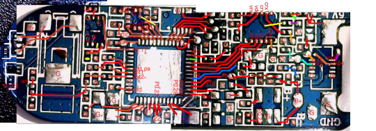
It wasn’t pretty but got the job done. I identified most of the components and connections.
Printed on board: “id101 ver 2.1 2016.06.13 3716″
Nordic nrf51822 qfaca1 1609ab - Bluetooth LE
hnox ver 2.2 2016.4.19 - HR sensor
Azoteq iqs263a - Captouch Controller
na45e - Battery charge or voltage regulator (?)
"8c630 og155r" sot-23-8? - Erm driver (?)
“2 w6 358411p ba 6" (15pin flex ribbon cable to SSD1306 oled
"1187-02 hxs 2016.09" - 4pin Digitizer 4
"ib 122" LGA-12? maybe Bosch Bma250e accelerometer (?)
Durning this time I finally met Ian and Jin from Dangerous Prototypes who told me about their little known Chinese reverse engineering service. For $80 they’ll reverse engineer a populated 2 layer PCB to Protel in a few days. I handed over $80 and a freshly purchased id101. After a few days Jin got back to me and said it was taking a bit longer. I forgot about it and a few weeks later I had a zip file with some nice pics of a 4 layer (oops) board which presumably slowed them down.


The zip also had the the Protel CAD files. Protel was apparently bought by Altium and is now subsumed into their ~$10k designer tool. I tried to obtain an old copy to run in a VM but it ended up being a huge pain in the ass and so I got bored and put this project down.
Recently, I found out that Altium’s free (though otherwise uncompetitive) online design tool Circuitmaker will actually import Protel files including PCBS. I opened that old zip file in there and found it looking pretty good!
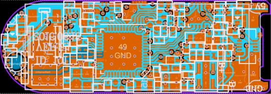
It probably took me a day or two of stitching screenshots, probing nets and marking up images in order to get my jpg. My working rate aside, $80 to get a fully interactive view of the board is worth it in every case I can think of.
Sadly, thats about where I left the id101 project. Find the id101 uploaded to my Circuitmaker account with the zipfile as an attachment. Something I’d love to try next would be to try to actually produce a device based on reverse engineered files.
1 note
·
View note
Link
Electronics circuit design with Circuitmaker +custom Arduino ##UdemyFrancais #Arduino #Circuit #Circuitmaker #Custom #Design #electronics Electronics circuit design with Circuitmaker +custom Arduino what you will learn about Circuitmaker: install and create project with schematic and PCB do all the setting of project and schematic find best component on octopart library community how to design schematic so it will be beautiful and readable how to define rules in schematic so we don't make any mistake in PCB design level Introduce best standard for everything that i used almost 8 years all shortcut and trick necessary for circuitmaker how to use net label and shaped net label How to use schematic error checking and how to fix them best method for annotating PCB rule checking and how to fix them Work with vias and what we should choose so all manufacturer can build our PCB How to know where to connect which pin so it will be easier to route measuring all kind of stuff on PCB from where we should start placing from where we should start routing How we can use other layers professionally How to use silk screen professionally How to work with 3DBodys How to create bill of material How to use Inspector Electronics: What is Arduino and how it work How we should filter reset signal so not any noise can effect it How to calculate how much width our track should have so can draw some amp that we want How Arduino can be programed How we can have custom Arduino Check some kind of regulator and choose which one is better to select What bypass capacitor is for and how we should use them and where we should place them Finding all type of component and talk about their packages Read all kind of datasheet together Look at all kind of capacitors and choose from them Talk about SMD and THD Component Why we should use crystal Choose right diode to protect our PCB How to calculate how much clearance our track should have so they don't arc where we should put crystal where to place bypass capacitor Make some improvement to Arduino Who this course is for: Electronics engineer Electrical engineer hardware engineer Computer engineer 👉 Activate Udemy Coupon 👈 Free Tutorials Udemy Review Real Discount Udemy Free Courses Udemy Coupon Udemy Francais Coupon Udemy gratuit Coursera and Edx ELearningFree Course Free Online Training Udemy Udemy Free Coupons Udemy Free Discount Coupons Udemy Online Course Udemy Online Training 100% FREE Udemy Discount Coupons https://www.couponudemy.com/blog/electronics-circuit-design-with-circuitmaker-custom-arduino/
0 notes
Text
aesthetic:
miles (prodigal-son -> cravat)
klavier (gavinner)
athena (widget-wisdom)
trucy (childofmagic)
larry (the-butz->laaaaaurice-> deauxnim)
justine (courtly-courtney)
bobby (for-justice)
byrne (yatagarasu)
aura (labcoat-lesbian)
metis (circuitmaker -> robot-gf)
shitpost:
phoenix (mister-wrong)
apollo (im-fine)
simon (fulltime-crier -> samurai-4-hire)
pearls (halfpintmedium)
gumshoe (best-pal)
badd (staccato-> dadd)
kay (actual-angel -> yatagara2u)
clay (starman-mediocre)
lang (lang-zi-says)
diego (17thcoffeecup -> in-waiting)
datz (thats-horrible)
#phoenix has 70 urls hoarded#neither starman-super nor starman-mediocre is taken im sorely tempted#i did it#anyway I deleted like 5 or 6 people i couldn't think of anything snappy for#please contribute
21 notes
·
View notes
Photo

PCB Design a Tiny Arduino In Altium CircuitMaker ☞ http://bit.ly/2PMuxzD #arduino
1 note
·
View note
Text
PCB design with Altium designer and Circuitmaker Full Bundle
PCB design with Altium designer and Circuitmaker Full Bundle
in this course we will cover all you need to design a pcb with very best altium
and even circuitmaker that is free and realy good and powerfull
first we learn how to create a component then we start a real world project
we will cover a project on smart home on altium designer then we design a custom arduino on circuitmaker
we cover all the basic like what component we should use and read all…
View On WordPress
0 notes
Photo

PCB Design a Tiny Arduino In Altium CircuitMaker ☞ https://goo.gl/kc3kaQ #Arduino #programming
1 note
·
View note
Text
PCB design with Altium designer and Circuitmaker Full Bundle
http://bit.ly/2q70g7B
PCB design with Altium designer and Circuitmaker Full Bundle, Complete PCB Design course Bundle from zero to hero on Altium Designer and circuit maker. All you need for PCB Design. In this course we will cover all you need to design a pcb with very best altium and even circuitmaker that is free and realy good and powerful first we learn how to create a component then we start a real world project we will cover a project on smart home on altium designer then we design a custom arduino on circuitmaker we cover all the basic like what component we should use and read all the datasheet together what regulator we should use to be enough and cost effective what is bypass cap and how we should choose them we talk about uart I2C ESP8266 and some kind of mcu and many more then we go to PCB and all the rule and calculation that you need to know what is the best placement and routing strategy next we go to advance stuff like snippet , master slave board , multichannel multiboard and many more next we will analyze power distribution at the how we should send our pcb to manufacturer with a lot of bonus content so lets begin
0 notes
Photo

PCB Design a Tiny Arduino In Altium CircuitMaker ☞ http://bit.ly/2BT5PZ7 #arduino #programming
0 notes
Text
Crash Course Electronics and PCB Design
Crash Course Electronics and PCB Design
Crash Course Electronics and PCB Design
Learn Electronics and PCB Design from the Ground up with Altium CircuitMaker and Labcenter Proteus.
What you'll learn
Students will be able to analyze and construct basic analog and digital circuits. Everything from filters and amplifiers to clocked and combinatorial digital circuits. As well as completely design printed circuit boards, assemble…
View On WordPress
0 notes
Text
Global PCB Software Market development and strategies
14-dec-2018 In 2017, the global PCB Software market size was million US$ and it is expected to reach million US$ by the end of 2025, with a CAGR of during 2018-2025.
This report focuses on the global PCB Software status, future forecast, growth opportunity, key market and key players. The study objectives are to present the PCB Software development in United States, Europe and China.
The key players covered in this study
• Mentor Graphics
• Candence
• Zuken
• Altium.
• CadSoft
• Novarm
• Shanghai Tsingyue
• Expresspcb
• Designspark
• KiCad EDA
• Autodesk
• Eagle
• DipTrace
• EasyEDA
• OrCAD
• CircuitMaker
• Fritzing
• P-CAD
Market segment by Type, the product can be split into
• Personal Version
• Professional Version
• Educational Version
Request a Sample Copy of This Report: https://www.radiantinsights.com/research/global-pcb-software-market-size-status-and-forecast-2018-2025/request-sample
Market segment by Application, split into
• Semiconductor Industry
• Electronics Industry
• Automotive Electronics
• Medical Equipment Design
• Others
Market segment by Regions/Countries, this report covers
• United States
• Europe
• China
• Japan
• Southeast Asia
• India
• Central & South America
The study objectives of this report are:
• To analyze global PCB Software status, future forecast, growth opportunity, key market and key players.
• To present the PCB Software development in United States, Europe and China.
• To strategically profile the key players and comprehensively analyze their development plan and strategies.
• To define, describe and forecast the market by product type, market and key regions.
In this study, the years considered to estimate the market size of PCB Software are as follows:
• History Year: 2013-2017
• Base Year: 2017
• Estimated Year: 2018
• Forecast Year 2018 to 2025
For the data information by region, company, type and application, 2017 is considered as the base year. Whenever data information was unavailable for the base year, the prior year has been considered.
Table of Contents
1 Report Overview
1.1 Study Scope
1.2 Key Market Segments
1.3 Players Covered
1.4 Market Analysis by Type
1.4.1 Global PCB Software Market Size Growth Rate by Type (2013-2025)
1.4.2 Personal Version
1.4.3 Professional Version
1.4.4 Educational Version
1.5 Market by Application
1.5.1 Global PCB Software Market Share by Application (2013-2025)
1.5.2 Semiconductor Industry
1.5.3 Electronics Industry
1.5.4 Automotive Electronics
1.5.5 Medical Equipment Design
1.5.6 Others
1.6 Study Objectives
1.7 Years Considered
Browse Full Research Report With TOC: https://www.radiantinsights.com/research/global-pcb-software-market-size-status-and-forecast-2018-2025
2 Global Growth Trends
2.1 PCB Software Market Size
2.2 PCB Software Growth Trends by Regions
2.2.1 PCB Software Market Size by Regions (2013-2025)
2.2.2 PCB Software Market Share by Regions (2013-2018)
2.3 Industry Trends
2.3.1 Market Top Trends
2.3.2 Market Drivers
2.3.3 Market Opportunities
3 Market Share by Key Players
3.1 PCB Software Market Size by Manufacturers
3.1.1 Global PCB Software Revenue by Manufacturers (2013-2018)
3.1.2 Global PCB Software Revenue Market Share by Manufacturers (2013-2018)
3.1.3 Global PCB Software Market Concentration Ratio (CR5 and HHI)
3.2 PCB Software Key Players Head office and Area Served
3.3 Key Players PCB Software Product/Solution/Service
3.4 Date of Enter into PCB Software Market
3.5 Mergers & Acquisitions, Expansion Plans
0 notes
Last Seen Blogs

luistillo
luis e.

arzenart
veemo

ujalanews
Ujala News

thevibrationofatoms
irreverent sincerity

cb1gallery
CB1 Gallery