#cloudhelp
Explore tagged Tumblr posts
Visit Tumblr Blog
Explore Tumblr blogs with no restrictions, modern design and the best experience.
Last Seen Tumblr Blogs


Fun Fact
Tumblr was created by web developers David Karp and Marco Arment.
Text
GAM 536-DPS936 3DSMAX Lab Eight: Smoke Simulation
In this lab, you are requested to complete the following tutorial provided by Autodesk. https://knowledge.autodesk.com/support/3ds-max/getting-started/caas/CloudHelp/cloudhelp/2018/ENU/3DSMax-Tutorial/files/GUID-F63B1A12-0D9D-42FB-88C6-7D8345413809-htm.html The tutorial uses particle flow to generate smoke. You are requested to complete the following items during the tutorial: Create a…
0 notes
Link
0 notes
Photo

0 notes
Text
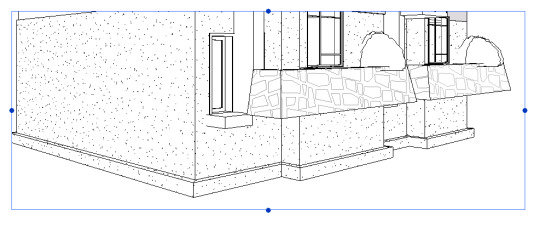
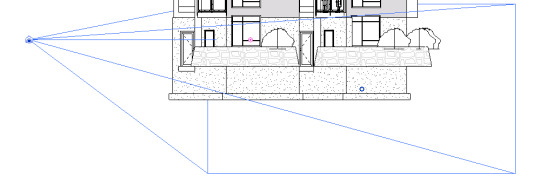
Camera Settings in Revit
For Creating a Perfect 3D Camera Shot
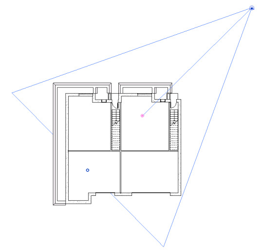
- Open the perspective 3D view. - In the Project Browser, right-click the perspective 3D view name, and select Show Camera. - The camera is selected in all views where the camera is visible, such as plan, elevation, and other 3D views.
Selected camera in plan view
Selected camera in 3D view
Selected camera in elevation view
- In the Project Browser, double-click the view in which you want to modify the camera position (for example plan or elevation). - Drag the camera to move it. The view updates according to the new camera position. - Drag the target to move it. The view updates according to the new target point. Select the perspective view. Drag the handles to vary the field of view (FOV).
https://knowledge.autodesk.com/support/revit-lt/learn-explore/caas/CloudHelp/cloudhelp/2016/ENU/RevitLT-DocumentPresent/files/GUID-DA6290AF-BE0B-43C5-9759-A874BAB5447B-htm.html
2 notes
·
View notes
Text
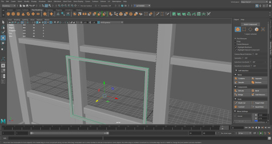
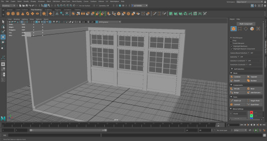
Window Frame
Continuing on with the mini brief, I next need to build the frames of the window.
To do this, I created a cube, resized it to fit within the border of the window. I cut out the front and the back of the cube. I manually selected each edge of the hollowed cube, Extrude with the Local Translate Z by 0.2, then selected Bridge, which filled in the inside of the frame.
At first, I used the Thickness option for the Extrude, but the hollow cube wouldn’t Bridge afterwards. If I Extruded outwards, it would clip through the window, but if I Extruded inwards, the cube would invert.
This was fixed when I toggled the Local Translate Z option, which I had no issue with and it Bridged perfectly.
The inner frame in both the top and bottom areas, were showing a black striped face. I tried Googling how to fix this and also numerous different ways to change it (such as deleting the face and re-bridging) but nothing worked. Then when I treat these faces as blackened faces and just reversed the mesh, they both became fully grey.
With these newly fixed faces, I used the original tutorial once again, but hit a bump when I realised that I don’t know how to (successfully) add new segments to a mesh. I found a new Youtube video that explained different methods of adding Edge Loops and/or segments. I’d decided to go with the fifth method, which is to use the Connect Tool
It did take some trial and error to learn how to use this tool correctly. Because I have a tendency to use the camera hotkeys (which require the ALT key + mouse buttons) and since the mouse keys are integral to using the Connect Tool, I kept trying to use the camera hotkeys to move the segments and/or pinch the segments.
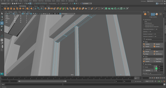


Happy with my framework, I decided to bevel the edges. Unfortunately, no matter which face or edge, I received the same error message,
“//Warning: Encountered a non-manifold vertex. Cannot Bevel.”
I could Bevel the outer frame, but the corners refuse to align.
-
-
-Resources
youtube
https://knowledge.autodesk.com/support/maya/learn-explore/caas/CloudHelp/cloudhelp/2019/ENU/Maya-Modeling/files/GUID-A7C41EA4-3249-4A24-A0AA-788D1F7D3DBF-htm.html
0 notes
Link
AutoCAD - MEASUREGEOM (Command)
2 notes
·
View notes
Text
Ovh Vps Docker

一.介绍 WireGuard是个新出的隧道程序,内核级的,所以数据处理能力以及资源消耗就会很理想,而且它可以工作于一方动态IP一方静态IP的环境下,这就能够很好的利用于内网穿透的环境下。当然,有几个大佬拿它做搭隧道来实现���己的全球大内网(x, 看得我也很是羡慕. Docker管理面板系列——云帮(RainBond/CloudHelp 出色的k8s管理面板) IDC零基础系列——CentOS6安装SolusVM(从系统分区到删库跑路) IDC零基础系列——Hetzner独服使用Proxmox创建VPS; 自建Git服务器系列——Gitea(Gogs的孪生兄弟) 自建Git服务器系列——Gogs(极易搭建的轻量级自助Git.
Get some hands-on experience with the latest stable Plesk release.
Plesk on a physical server or VM
The easiest way to install Plesk on your physical server or virtual machine running Linux is to use our Web Installer.
More of a Windows fan? Download the Windows Installer and run the following command: El capitan create bootable usb.
Plesk is installed with a full-featured 14-day trial license. Always install Plesk on a fresh server, and make sure to read the software requirements before installation. https://loadpolar419.tumblr.com/post/654236565253603328/magnet-app-for-mac-free-download.
Plesk in the cloud
Do not have a server? Many cloud providers offer Plesk images in their marketplaces. It is a great way to quickly deploy a server with Plesk pre-installed.
Plesk in Docker
Plesk in Docker is great for developers looking to create an extension for Plesk, or as a local dev environment.
Ovh Vps Docker Compose
To run Plesk in Docker, follow these steps:

Ovh Vps Docker Command
Download and install Docker on your laptop/desktop.
Once Docker is installed and running, run the following command: Office 2015 mac download.
Access Plesk in your browser using the Docker host IP address and port 8880 (e.g. https://192.0.2.2:8880). The default administrator credentials are admin / changeme.
0 notes
Text
Comandos 4
DTEXT
Centers the text both horizontally and vertically at the middle of the text. Available for horizontally oriented text only.
The MC option differs from the Middle option in that it uses the midpoint of the height of uppercase letters. The Middle option uses the midpoint of all text, including descenders.
MR (Middle Right)
Right-justifies text at a point specified for the middle of the text. Available for horizontally oriented text only.
BL (Bottom Left)
Left-justifies text at a point specified for the baseline. Available for horizontally oriented text only.
BC (Bottom Center)
Centers text at a point specified for the baseline. Available for horizontally oriented text only.
BR (Bottom Right)
Right-justifies text at a point specified for the baseline. Available for horizontally oriented text only.
Style
Specifies the text style, which determines the appearance of the text characters. Text you create uses the current text style.
Entering ? lists the current text styles, associated font files, height, and other parameters.
ATTACH
Displays a bitmap of the selected file when you choose Views Preview in the dialog box. To save a bitmap with a drawing file, use the Save a Thumbnail Preview Image option on the Open and Save tab in the Options dialog box.
File Name
Displays the name of the file you select in the Files list. If you select multiple files, File Name displays each selected file within quotation marks. You must use quotation marks when entering multiple file names. You can use wild-card characters to filter files displayed in the Files list. For information on wild-card searches, see Wild-Card Characters Reference.
Files of Type
When you are saving files, Files of Type specifies the format in which the file is saved.
Select Initial View
Displays the specified model space view when you open the drawing if the drawing contains more than one named view.
Update Sheet and View Thumbnails Now
Reflects the current setting of the UPDATETHUMBNAIL system variable. This option temporarily overrides, but does not change the current setting of UPDATETHUMBNAIL.
Open/Save
Depending on the purpose of the specific file selection dialog box, opens or saves the selected file or enters the path of the selected folder in the previous dialog box. Certain file selection dialog boxes may include additional options, accessed by clicking the arrow next to the Open button.
Open Read-Only
Opens a file in read-only mode. You cannot save changes to the file using the original file name.
Partial Open (not available in AutoCAD LT)
Displays the Partial Open dialog box. You can open and load a portion of a drawing, including geometry on a specific view or layer. The PARTIALOPEN command can be used only for drawings in AutoCAD 2004 or later format.
Partial Open Read-Only (not available in AutoCAD LT)
Opens the specified drawing portions in read-only mode.
PASTESPEC
Pastes objects from the Clipboard into the current drawing and controls the format of the data.
Find
The Paste Special dialog box is displayed.
PURGE
Removes unused named objects, such as block definitions and layers, from the drawing using the command line.
Summary
Removes unused named objects from a drawing at the Command prompt. You can only remove one level of reference at a time. Repeat the command until there are no unreferenced, named objects.
Note: The PURGE command will not remove unnamed objects (zero-length geometry or empty text and mtext objects) from blocks or locked layers.
List of Prompts
The following prompts are displayed.
Type of Unused Objects to Purge
You can specify what types of named objects that you want to remove, including blocks, detail view styles, dimension styles, groups, layers, linetypes, materials, multileader styles, plot styles, shapes, text styles, multiline styles, section view styles, table styles, visual styles, registered applications, zero-length geometry, empty text objects, and obsolete DGN linestyle data (orphaned data), or all of these.
Enter Name (s) to Purge
Enter an object name of * to list the objects.
Verify Each Name to Be Purged?
Enter y to verify each name.
SPLINE
Creates a smooth curve that passes through or near a set of fit points, or that is defined by the vertices in a control frame.
Find
SPLINE creates curves called nonuniform rational B-splines (NURBS), referred to as splines for simplicity.
Splines are defined either with fit points, or with control vertices. By default, fit points coincide with the spline, while control vertices define a control frame. Control frames provide a convenient method to shape the spline. Each method has its advantages.
To display or hide the control vertices and control frame, select or deselect the spline, or use CVSHOW and CVHIDE. However, for splines created with control vertices in AutoCAD LT, you can display the control frame only by selecting the spline.
The prompts differ, depending on whether you choose Fit or CV (control vertices) as the creation method (Method option).
First Point
Specifies the first point of the spline, either the first fit point or the first control vertex, depending on the current method.
Next Point
Creates additional spline segments until you press Enter.
Undo
Removes the last specified point.
Close
Closes the spline by defining the last point to be coincident with the first. By default, closed splines are periodic, maintaining curvature continuity (C2) along the entire loop.
Method
Controls whether the spline is created with fit points or with control vertices. (SPLMETHOD system variable)
Fit
Creates a degree 3 (cubic) B-spline by specifying fit points that the spline must pass through. When the tolerance value is greater than 0, the spline must be within the specified tolerance distance from each point.
Control Vertices (CV)
Creates a spline by specifying control vertices. Use this method to create splines of degree 1 (linear), degree 2 (quadratic), degree 3 (cubic), and so on up to degree 10. Adjusting the shape of a spline by moving control vertices often provides better results than moving fit points.
Object
Converts 2D or 3D quadratic or cubic spline-fit polylines to equivalent splines. The original polyline is retained or discarded depending on the setting of the DELOBJ system variable.
Prompts for Splines with Fit Points
The following prompts are specific to the fit point method.
Knots. Specifies the knot parameterization, one of several computational methods that determines how the component curves between successive fit points within a spline are blended. (SPLKNOTS system variable)
Chord. ( Chord-Length method) Spaces the knots connecting each component curve to be proportional to the distances between each associated pair of fit points. An example is the green curve in the illustration.
Square root. (Centripetal method) Spaces the knots connecting each component curve to be proportional to the square root of the distance between each associated pair of fit points. This method usually produces “gentler” curves.
Uniform. (Equidistant method). Spaces the knots of each component curve to be equal, regardless of the spacing of the fit points. This method often produces curves that overshoot the fit points.
Start Tangency
Specifies a tangent condition on the starting point of the spline.
End Tangency
Specifies a tangent condition on the ending point of the spline.
Tolerance
Specifies the distance by which the spline is allowed to deviate from the specified fit points. A tolerance value of 0 requires the resulting spline to pass directly through the fit points. The tolerance value applies to all fit points except the starting and ending fit points, which always have a tolerance of 0.
Prompts for Splines with Control Vertices
The following prompt is specific to the control vertices (CV) method. (SPLMETHOD system variable)
Degree
Sets the polynomial degree of the resulting spline. Use this option to create splines of degree 1 (linear), degree 2 (quadratic), degree 3 (cubic), and so on up to degree 10.
APA
AUTODESK HELP (Abril del 2021) DTEXT Command (Consultado el 8 de Abril del 2021) https://knowledge.autodesk.com/support/autocad/learn-explore/caas/CloudHelp/cloudhelp/2020/ENU/AutoCAD-Core/files/GUID-45F9C588-2BA9-414D-8AFD-FB6B448BF273-htm.html
AUTODESK HELP (Abril del 2021) ATTACH Command (Consultado el 8 de Abril del 2021) https://knowledge.autodesk.com/support/autocad/learn-explore/caas/CloudHelp/cloudhelp/2021/ENU/AutoCAD-Core/files/GUID-CF5780AD-D1AB-4526-9608-83D7952749E7-htm.html
AUTODESK HELP (Abril del 2021) PASTESPEC Command (Consultado el 8 de Abril del 2021) https://knowledge.autodesk.com/support/autocad/learn-explore/caas/CloudHelp/cloudhelp/2020/ENU/AutoCAD-Core/files/GUID-E8C1190C-A26C-484C-ADDD-DDF81666F69F-htm.html
AUTODESK HELP (Abril del 2021) PURGE Command (Consultado el 8 de Abril del 2021) https://knowledge.autodesk.com/support/autocad/learn-explore/caas/CloudHelp/cloudhelp/2019/ENU/AutoCAD-Core/files/GUID-C60B6D5D-AAEB-420F-917F-6E6B47E92F48-htm.html
AUTODESK HELP (Abril del 2021) SPLINE Command (Consultado el 8 de Abril del 2021) https://knowledge.autodesk.com/support/autocad/learn-explore/caas/CloudHelp/cloudhelp/2021/ENU/AutoCAD-Core/files/GUID-EA2D8ACA-336A-4656-BFD3-43BC371C6171-htm.html
0 notes
Video
tumblr
Final 3d animation - “Bing”
Here you can see the improved version of “Bing” animation. After reading some tips on the Maya website, and experimenting I was able to create this piece of animation. Now it’s much more visible.
link to the forum I used” https://knowledge.autodesk.com/support/maya/learn-explore/caas/CloudHelp/cloudhelp/2020/ENU/Maya-LightingShading/files/GUID-A0B3AA95-327B-4D65-B26D-AA42D0008824-htm.html
#animation#finalanimation#finalproject#university#3dmodelling#3dart#3danimation#shortmovie#soundeffect#sound
0 notes
Link
0 notes
Text
GAM 536-DPS936 Game Content Creation Lab Three
In this lab, you are requested to complete the following tutorial from Autodesk: https://knowledge.autodesk.com/support/3ds-max/getting-started/caas/CloudHelp/cloudhelp/2018/ENU/3DSMax-Tutorial/files/GUID-5BA72891-97EC-4688-8B50-9FACCF1FF040-htm.html You will need some required files to start the tutorial which you can download from the following…
0 notes
Photo

對齊工具(Align tool)
選中兩物件後去modify>align tool會出現一虛擬方盒 讓物件可以互相對齊
(先選的物件是客人 會移動 候選的物件是標的 被用來對齊)
虛擬方盒有一些把手 可以用來對齊不同的面或不同面向的物件中心
[長按] : 記得 把手 可以 先 按著不放 就會如圖一 那個黃色的面顯示說
接下來是對齊哪邊
[轉視角] : 記得有的把手要轉視角才會出來
請根據自己需求轉視角 ------------ Align tool To align objects using an interactive manipulatorSelect Modify > Align Tool. https://knowledge.autodesk.com/support/maya/learn-explore/caas/CloudHelp/cloudhelp/2018/ENU/Maya-Basics/files/GUID-8345A56F-C6E2-4D0B-BD1A-EC4E6D4B574D-htm.html
0 notes
Text
Exploring 3D Animation & Rigging
18/02/2021
RP4222 - Post 16
Time has been spent recently looking into tutorials on 3D animation and rigging for potential model comparisons. There are many online tutorials through YouTube and Udemy that are helpful. One of the first websites to be viewed was the Autodesk Maya website, (Autodesk, 2021), in hoping to further knowledge and understanding of the subject. This had a series of short videos of setting up a rig for a model 3D Lion and then animating to completion. However, this was more showcasing what could be achieved through animating in Maya rather than any useful information. However, another part of the Autodesk website did contain useful information about 3D animation, its uses and the industries it is used in. This lead to a series of articles on the subject as well as links to Autodesk tutorials located on YouTube. https://www.autodesk.co.uk/solutions/3d-animation-software. (Autodesk, 2021).
https://knowledge.autodesk.com/support/maya/learn-explore/caas/CloudHelp/cloudhelp/2020/ENU/Maya-CharacterAnimation/files/GUID-0D0DCBE5-01BA-4AA2-BC4D-85C3285933AD-htm.html (Autodesk, 2021). These websites linked explained the uses of the software and a break down of how characters can be animated.
0 notes
Photo


Retexturing the room.
Because the UV’s on the room were not well made (image 1) I worked on remapping it completely. I remapped and realigned all the UV’s (from the walls). I used the checker texture to check the sizing of the pieces and make sure things line up. Tomorrow I will work on other objects from the room. To remap them as well.
To help me, I used the notes I made from Freark’s classes and some stuff I found online:
https://knowledge.autodesk.com/support/maya/learn-explore/caas/CloudHelp/cloudhelp/2020/ENU/Maya-Modeling/files/GUID-73BF7546-3BF2-44F3-9192-15A024CEC173-htm.html
https://knowledge.autodesk.com/support/maya/learn-explore/caas/CloudHelp/cloudhelp/2020/ENU/Maya-Modeling/files/GUID-1CEF8A5B-1051-40F1-ACFE-F29AD066F56F-htm.html
0 notes
Photo


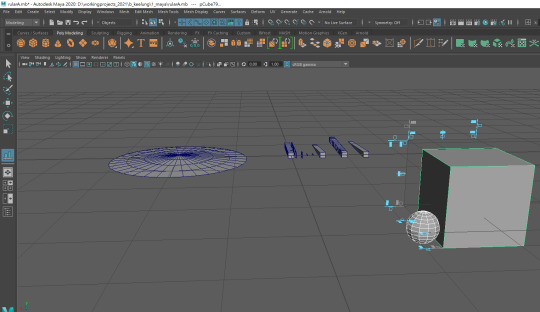
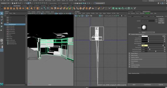
I found this video a few weeks ago https://youtu.be/975S-9URarQ and I thought it would work well for the beach running and wave over capsule parts of the surrealism sequence and it does render in Arnold, unlike the other ones I was finding. I made rounded blobs as the water pattern so that I could use it as a collider and have the water particles flowing around them. However, I tried following the tutorial exactly and the emitter stopped working after about 2 minutes and wouldn’t emit anything.
https://knowledge.autodesk.com/support/maya/learn-explore/caas/CloudHelp/cloudhelp/2018/ENU/Maya-SimulationEffects/files/GUID-F338DF02-88D8-47CF-B205-89F2448E888D-htm.html
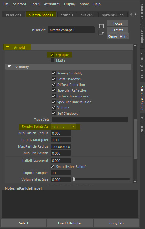
From here I decided to ditch the tutorial and try using an object emitter independently and have the particles hit the water pattern (set to be a rigid object/collider) and then flow around them. What ended up happening was that they would hit the first row and then start wildly bouncing off in every other direction. To get this to render in Arnold I set it to render as spheres in both in the Shading and Arnold attribute menus for the particle effect. This would likely also solve the problem we had trying to get the particle cloud and galaxies to render.

To get the particles to travel upwards and not also bounce off in every direction, I had to change the way they emitted so that they were emitting from the water pattern shapes themselves. That, however, meant that I needed to have them included in the scene rather than just being colliders, I tried to convert them into a water-like texture and it does distort like water/glass in the renders. In the viewport, the pattern looks invisible but you can see the particles moving around/inside it.


Scarlett had kindly given me the external shell model for the Rocket so I was able to put that with Veronika’s model and fixed texture in the scene.

I gave the scene a more Dutch Tilt/Angle to get that off-kilter feel that the angle in the original panel had. This also ties in a little to Holly’s research into the distorted models/angles to get the look desired. Of course, I can’t quite replicate the panel exactly because most of the panels were drawn with just the capsule’s internal frame and not counting for the shell that would be over it but this twist adds a bit of interest into the shot rather than just having a front-facing camera.

For the 3D Animatic I tried to give it a bit more of a water feel by overlaying a solid blue layer with a very light opacity just to slightly tint it but this is what it normally looks like.
vimeo
I tried to use this same emitter type to recreate the beach waves section and nearly had it working but it stopped working about 10 minutes before the deadline we’d set for things to be rendered out and I was having trouble with the camera/backgrounds. I will try and get that working and made into a scene either in the holidays or just after them. I will also try again with getting the particles to move around the water texture but this does also work.
0 notes
Text
Issue with the audio...
While working, the audio suddenly stopped working. I can’t hear it when I play the animation but I can hear it when I scrub through the animation. Then I read through some articles and other people set it to real time and I wasn’t sure whether I was correctly setting it to real time or not.
I asked my lecturer what can I do and she suggesting removing and reimporting the audio and asked me to check whether the audio works in my earlier files.
I removed the track and reimported them and checked my old files and the audio seems to be completely fine in those. I already put so much effort into the current file and the thought of working on a previous file was just... tiring. And I was worried about the time limit for 11 second club deadline. So I kept looking for more ways to get the audio working again because a lot of the people in the articles I’ve read have solved their problems and I had hope to solve mine too. My lecturer told me if it keeps persisting, import the animation I’ve worked on into a new scene and then add the audio track again.
I did somehow get to work! Apparently the icons where different from mine because of the different versions and after I figured this out and set it to real time, I got it to work!
All the articles I read during this:
https://forums.cgsociety.org/t/sound-not-playing/1067775
https://knowledge.autodesk.com/support/maya/learn-explore/caas/CloudHelp/cloudhelp/2018/ENU/Maya-Animation/files/GUID-51A80586-9EEA-43A4-AA1F-BF1370C24A64-htm.html
https://knowledge.autodesk.com/support/maya/learn-explore/caas/CloudHelp/cloudhelp/2020/ENU/Maya-Animation/files/GUID-9853B7B5-8AD5-46F6-A921-A3771A505AD1-htm.html
https://knowledge.autodesk.com/support/maya/learn-explore/caas/CloudHelp/cloudhelp/2020/ENU/Maya-Animation/files/GUID-68334DC8-71A5-4B37-BCB0-7AA97E4A08CB-htm.html
https://knowledge.autodesk.com/support/maya/learn-explore/caas/CloudHelp/cloudhelp/2018/ENU/Maya-Animation/files/GUID-435C0480-0FBC-4334-86E5-C7FF9A685888-htm.html
0 notes