#iMX6UL System on Module
Explore tagged Tumblr posts
Visit Tumblr Blog
Explore Tumblr blogs with no restrictions, modern design and the best experience.
Last Seen Tumblr Blogs


Fun Fact
Tumblr has been banned in Indonesia for providing people with access to pornographic content.
Text
Forlinx FET-SoM-iMX6UL-C1 System on Module / Computer on Module

FETMX6UL-C1 is a commercial grade system on module designed based on NXP i.MX 6UltraLite processor featuring ARM Cortex-A7 kernel with main frequeny of 528MHz. Size only 40mmx50mm, 6-layer PCB immersion gold process, board-to-board connector with anti-mis-insertion design, convenient for software and hardware debugging, accelerating product launch time.
Compared with ARM9 and ARM11, FETMX6UL SoM reduces power consumption by 50%. It integrates all the functions of the processor, supports up to 8 UART, 2 Ethernet, 2 CAN and other industrial-grade bus interfaces, and can be applied to various embedded solutions.
Feature of i.MX 6UltraLite processor
Expanding the i.MX 6 series, the i.MX 6UltraLite is a high-performance, ultra-efficient processor family featuring an advanced implementation of a single Arm® Cortex®-A7 core, which operates at speeds up to 696 MHz.
The i.MX 6UltraLite applications processor includes an integrated power management module that reduces the complexity of external power supply and simplifies power sequencing. Each processor in this family provides various memory interfaces, including 16-bit LPDDR2, DDR3, DDR3L, raw and managed NAND flash, NOR flash, eMMC, Quad SPI and a wide range of other interfaces for connecting peripherals such as WLAN, Bluetooth™, GPS, displays and camera sensors.
0 notes
Text
Ethernet Compliance Testing at Toradex
Introduction
Toradex offers robust and reliable embedded systems, which are required to work continuously in harsh environments. Ethernet is one of the most important interfaces for the Internet of Things (IoT). We will review some Ethernet standards and show you how Toradex tests for compliance with them.
After looking at the standards, we’ll describe our test configuration, test procedures, and the test results. A Colibri iMX6ULL SoM and Iris Carrier Board were used in this example, but you can use this as a model for testing custom carrier boards if that testing will be part of your verification process.
Why We Use Standards and Do Compliance Testing
Ethernet designs adhere to the IEEE 802.3 standard, which defines the Physical and Data Link layer of the seven-layer Open Systems Interconnection (OSI) model. Waveform characteristics are specified in the standard. Designing to this standard allows compatibility and interoperability with other devices, in all kinds of environments all over the world. Otherwise, transmission issues and data losses are likely to occur. Compliance testing ensures that the implementation meets the standard.
In addition to the waveform characteristics specified in the IEEE 802.3 standard, the University of New Hampshire InterOperability Laboratory (UNH-IOL) has provided standard conformance test procedures for those signals.
The documents can be found at these links:
https://ieeexplore.ieee.org/browse/standards/get-program/page/series?id=68
https://www.iol.unh.edu/
Ethernet Physical Layer Basics
The Ethernet standard is several thousand pages, so we’ll just cover the most important concepts and some key terminology.

Figure 1 OSI Reference Model from IEEE Standard for Ethernet
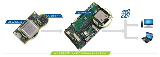
Let’s start with the physical medium. Signals typically arrive through a twisted pair copper cable to an Ethernet jack with magnetics on our Carrier Board, then continue through impedance matched differential traces on the PCB to the Ethernet PHY IC. This device converts analog signals from the medium to digital signals for the processor and vice versa.
The electrical signals first encounter the Medium Dependent Interface (MDI) of the PHY, a part of the Physical layer. Different physical media have different characteristics. In accordance with the specific kind of the media, the signals are transformed and sent to the next layer of the OSI-model, the Data Link Layer. We provide 10Base-T and 100Base-TX (Fast Ethernet) on our Colibri Modules and 1000Base-T (Gigabit) on the Apalis modules. The standardized interface between the first two OSI-layers is called Media Independent Interface (MII) and is independent of the physical layer.
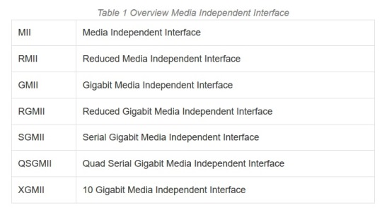
Meanwhile, we are talking about the advanced backward-compatible Reduced Gigabit Media Independent Interface (RGMII) and the next interface for the 10 Gigabit is already named as XGMII. Reduced means that there are fewer signals needed for the same standard. The xMII’s are parallel data buses. There is a supplementary serial bus for management purpose called Management Data Input/Output (MDIO). The xMII interface ends at the Media Access Control (MAC) layer. Here the well-known MAC address is used as a unique identifier. The MAC layer can be integrated with the System on Chip (SoC), like on NXP® processors. But it could be already embedded in the same IC as the PHY, which is better known as an Ethernet Controller. The Ethernet Controller IC, in turn, is connected with the SoC through a separate interface like USB or PCIe. Note that we are not looking at higher OSI layers and protocols like ARP, NDP, IP, TCP, UDP, etc., which are organized in frames and packages, because for all these protocols the electrical characteristics on the first physical levels are the same!
For now, let’s go back to the physical layer. There are 2 main characteristics of the physical link I’d like to expand on, namely, speed and duplex mode. Our modules support speeds up to 1Gbit on Apalis Modules and 100Mbit on Colibri Modules, and both half and full duplex modes. In full duplex mode of operation, PHYs on both ends of the link can communicate with each other simultaneously. For the half duplex mode, where the PHY can’t receive and transmit data at the same time, there need to use the Carrier Sense Multiple Access with Collision Detection (CSMA/CD) to avoid collisions and control the data flow.
As already described, our Apalis Modules are capable of Gigabit Ethernet, but how do the communication partners know with which speed they can send the data? An-auto negotiation procedure exists, where the linking partners set the best link trough 16ms link pulses. Please be careful with auto-negotiation settings, as there is a well-known problem of the duplex mismatch, when the linking partners are configured in a fixed way. On the electrical side of the physical layer 10Base-T and 100Base-TX use two twisted pairs while 1000Base-TX uses 4. 100Base-TX is faster than 10Base-T based on the much faster frequency of 62.5 MHz instead of 10 MHz and denser signal modulation scheme (PAM-3). 1000Base-TX uses the same frequency as 100Base-TX, but transmits across 4 twisted pairs and with a higher level of modulation (PAM-5). Finally, there is an additional feature called EEE, Energy Efficient Ethernet. The aim of this standard is to save energy.
https://www.analog.com/media/en/technical-documentation/application-notes/EE-269.pdf
https://en.wikipedia.org/wiki/Duplex_mismatch
https://en.wikipedia.org/wiki/Media-independent_interface
https://www.asix.com.tw/new_alias.php?alias=93&full=http://www.embedded.com/design/202804534
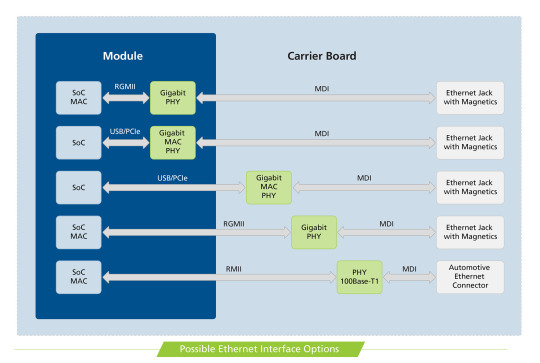
The picture below summarizes the Ethernet possibilities on the Toradex SoM approach:
Automotive Ethernet
Before we continue to the Compliance Testing, I want to quickly let you know that I receive a lot of questions about 100Base-T1, better known as Automotive Ethernet. The customers want to know, if it is possible to connect Automotive Ethernet to a fast Ethernet PHY. The 100Base-T1 has a different physical layer specification to fulfill the requirements in a harsher automotive environment. It is not possible to connect it, but the MII is still the same! The solution is to connect the 100Base-T1 PHY to the Multimedia Independent Interface of the SoC directly. Consequently, a Module with an xMII on the Module Edge Connector must be selected! Of course, you have to design your Custom Carrier Board with a 100Base-T1 PHY. Here you can find the list of Toradex Modules which provide an xMII on the edge connector. Please note that this is not a Standard Toradex Interface and the pin assignment varies with each module.
Apalis iMX8
Colibri iMX8X
Colibri iMX7
Colibri iMX6ULL
Colibri Vybrid
Ethernet Compliance Testing for Toradex Systems

Figure 2 10Base-T Test: DOV Internal MAU Normal
After this very short overview, I want to continue with the compliance testing, where we test the electrical signals in time and voltage. The electrical signals look totally different for the 10/100/1000 Mbps and have different requirements as you can see in the oscillograms.
The tests evaluate the voltage amplitudes, jitter values, rise/fall times and other signal characteristics. For each test a defined test signal must be generated by the DUT, e.g. a continuous pseudo-random signal has to be emitted. The easiest way to test the signal requirements is to define a test mask. The signals must not intersect with the mask in order to fulfill the specification. The 10Base-T tests are very often defined through a test mask, as you can see in the first figure. I want to mention some values: The Peak Differential Output Voltage must be between 2.2 V and 2.8 V. The Differential Output Voltage Harmonics must be greater than 27 dB and all Jitter values must be smaller than 22 ns. Very interesting is the twisted-pair model for 10Base-T, which must be used for some compliance tests. With the equivalent circuit based on lumped elements, it is possible to model multiple different transmission elements with just passive components. Depending on the PHY a linking partner is needed for 10Base-T compliance tests. You can download the Test Report of Colibri iMX6ULL as an example, where you can find all tests.

Figure 3 Measured differential random 10Base-T signal without load
The interface characteristics for 100Base-TX are defined in table 2 based on the MLT-3 voltage signals with three levels. The data is encoded before with 4B5B algorithm, so a clock recovery out of the data stream is possible because a level transition is forced. For our test equipment, a pseudo-random test pattern (PRBS7) is enough for all the tests. However, some tests only trigger on defined patterns and measures only at that moment the specific values.
Table 2 Interface Characteristics 100Base-TX Characteristics Min Max Unit UTP DOV Base to Upper/Lower 950 1050 mV Signal Amplitude Symmetry 98 102 % Rise/Fall Time 3 5 ns Rise/Fall Time Symmetry 0 500 ps Duty Cycle Distortion -250 250 ps Transmit Jitter 0 1.4 ns Overshoot 0 5 %

Figure 4 Measured differential random signal 100Base-TX
The test criteria are defined in a similar manner for the 1000Base-T. I am not going to list them. For these tests an additional disturber in the form of an Arbitrary Waveform Generator (AWG) is needed to create the required disturbing signals with the frequency of 31.25 MHz and 20.833 MHz. In figure 5 you can see the test pattern of test mode 1 produced by the PHY. There are four different test patterns, which can be generated through PHY’s MDIO register settings. Please don’t forget that we have to perform the compliance test four times, because of the four twisted pairs.

Figure 5 Definition of Test Mode 1 Waveform 1000Base-T from IEEE Standard for Ethernet

Figure 6 Measured differential Test Mode 4 Distortion Test 1000Base-T without disturber
We have now seen some of the electrical requirements that must be fulfilled to be compliant with the interface definition. Before we have a closer look at the test equipment, I want to try and solve the most important question of this Blog: How do you generate those test signals?
Each PHY vendor has a custom method to modify the necessary register settings to enter the test modes. That is often not publicly available, and you must ask your PHY vendor. A very good example is Microchip, who has provided all information about Ethernet Compliance in one document since last year. These are the Ethernet PHYs, which we use in our modules, KSZ8041 and KSZ9031. I also want to share a document from TI with you, just as a further example. If you are looking for a new Ethernet PHY and want to do Ethernet Compliance Testing, please ask your vendor for detailed information about the register settings in advance!
http://ww1.microchip.com/downloads/en/AppNotes/AN2686-Ethernet-Compliance-Test-10BASET-100BASETX-1000BASET.pdf
http://www.ti.com/lit/an/snla239a/snla239a.pdf
Test Equipment
As depicted above, we must measure some picoseconds precisely. For that we need very good tooling. You should use an oscilloscope with a bandwidth of 1 GHz and memory of 4MS or greater. Usually you need a test fixture, which transforms the Ethernet signals from an Ethernet Jack to the oscilloscope input channels. That is why we work closely with Teledyne LeCroy. We have a great collaboration on a technical level. We use a high-end oscilloscope from the WaveMaster series with appropriate hardware and software tools. Of course, there is equipment from other vendors available like Tektronix, Rhode&Schwarz, Keysight and others.
Quotation from Mr. Hofferbert, specialist at Teledyne LeCroy:
“Teledyne LeCroy is a leading manufacturer of digital storage oscilloscopes (DSO). With modern DSOs it is possible to perform qualification measurements. Toradex uses appropriate equipment from Teledyne LeCroy to test the design of Ethernet PHYs. With the combination of our QualiPHY Software and latest oscilloscopes, a semi-automatic test has been implemented to test the physical level of the Ethernet PHYs according to the IEEE 802.3 specification. This measurement solution allows the development engineers at Toradex to test and resolve issues with signal integrity in an early development stage of their embedded systems. Toradex is very interested in using the measurement equipment as efficiently as possible. If there are any uncertainties or measurement deviation, we work together to quickly solve these issues and provide our expertise in measurement application.” Gregor Hofferbert, Teledyne LeCroy
www.teledynelecroy.com
http://cdn.teledynelecroy.com/files/manuals/qualiphyenetmanual.pdf
Conclusion
After performing a compliance test, we can create a compliance report to verify our PCB design. As you can see in the test report from Teledyne LeCroy, the Colibri iMX6ULL with Iris Carrier Board is compliant with 10Base-T and 100Base-TX standard. So, we are sure that our implementation will work with other compliant systems. We can share with confidence our PCB implementation of the Ethernet Interface with our customers. You can find the Carrier Board Design Guides here: https://developer.toradex.com/carrier-board-design
We also share our Carrier Boards Designs as Altium Designer projects for free with our customers. We provide a lot of help through our community channel as well: https://www.toradex.com/community
We started to implement and provide our testing SW in our latest BSP. We adopt the existing drivers to be easily run with our modules to perform Compliance Tests. But again be careful, for each PHY you need different SW techniques to get the test pattern. There is no simple handbook. For example: https://git.toradex.com/cgit/linux-toradex.git/commit/?h=tegra-next&id=13bd0f089ac6babeb7248fe3db4b9c19233cce3c
But issues can occur with wrong routing, bad ground layout, or inaccurate crystal circuit design. It also depends on the testing environment. Ground loops and noisy or underpowered power supplies can cause measuring errors. It is important to follow the design guides of the PHY vendors. I like the troubleshooting document provided by Intel, that you can use for the first debug consultation. There is a basic overview of failures and possible sources. Designs with too long traces, low quality magnetics or improper use of the measurement equipment can always be the source of failing the compliance test. But there are also specific errors which can be put in a strong correlation. E.g. wrong amplitude values are often caused by wrongly assembled bias resistors or issues with the centre tap circuits. Whereas too high Jitter values are due to crystal issues, impedance mismatch or bad power supply. In general, your Ethernet PHY vendor should be able to help you, probably even with a schematic or layout review.
https://www.intel.com/content/dam/www/public/us/en/documents/application-notes/ieee-conformance-phy-app-note.pdf
In this blog, I gave you some insights to one of the many verifications Toradex does to achieve such high-quality products. Internal testing by us and your adherence to our design guides reduces your risk to a minimum. For the highest quality, you can do your verification with your own customized carrier board, and that you follow the system engineering approach (as documented by NASA, for instance) which recommends testing in early stages to reduce risk and cost. I hope I gave you plenty of information to get started. If you need more information feel free to reach out.
#Ethernet Compliance Test#Apalis iMX8#Colibri iMX6Ull#Development Boards#NXP i.MX 8#NXP i.MX 6ULL#System on Module#Computer on Module
0 notes
Text
Poky linux kernel

Poky - eL.
Out-of-Tree Kernel Modules - Legato Docs.
Make(3): execvp: /bin/sh: Argument list too long --Compilation Error.
Enable AD7298 with IIO on imx6ul with Yocto - Q&A - Linux Software.
KGDBoE on RaspberryPi - building out of the kernel tree.
Compiling Linux | Documentation | RocketB.
GitHub - chargebyte/poky.
(poky) Custom Kernel Recipe: How to specify KCFLAGS args during kernel.
Atmel-aes Linux driver works on the sama5d31ek board.
Dunfell - ERROR: ca-certificates-20211016-r0 do_fetch: Fetcher failure.
What is Poky and Bitbake in the Yocto Project - Tutorial.
How to use Poky — pengwyn-sdk 1.0.0 documentation.
Poky – Yocto Project.
Reconfiguring Linux kernel and adding drivers into Galileo's.
Poky - eL.
For how to compile the fmac backport driver, we have a README file along with the release. #1. Untar the Cypress backports package. #2. (Native) compile local tools and generate (in a new terminal. #3. (Cross) compile kernel modules. #4. The kernel modules are available here. The following steps will recreate the kernel and device tree for the MitySOM-A10S development kit. This will use the yocto SDK that is provided on the files section. Please note that the kernel and dtb will normally be built through the yocto build but the steps here are provided for development.
Out-of-Tree Kernel Modules - Legato Docs.
Poky Linux. Poky is an embedded Linux build system, distribution and developer environment which builds upon OpenEmbedded technologies. It is less generic than OpenEmbedded, but on the other side, you may find it more tuned and optimized for such devices as PDAs and smartphones.... Linux kernel has Root on NFS feature, allowing mounting root. Indeed this is the case. The actual problem command is buried inside the kernel's build system and is quite hard to find. But the reason it is too long is because the $(c_flags) variable is huge. This is huge because qualcomm's wifi driver has a poor design for its headers. Feb 24, 2016 · The steps I did to build the custom image: (1) Build standard image. (2) source poky/oe-init-buid-env (step 4 in the Board support package on page 7) (3) bitbake virtual/kernel -c menuconfig (step 1 in the Board support package on page 14) (4) include your stuff.
Make(3): execvp: /bin/sh: Argument list too long --Compilation Error.
Loadable kernel modules ( files) are object files that are used to extend the kernel of the Linux Distribution. They are used to provide drivers for new hardware like IoT expansion cards that have not been included in the Linux Distribution.
Enable AD7298 with IIO on imx6ul with Yocto - Q&A - Linux Software.
. Aug 03, 2007 · Through integration with QEMU (both ARM and x86 host virtualisation) or chroot-like tools, Poky provides a unique cross-application development environment. Features include; * Linux 2.6.x kernel support. * x86 and ARM (both OABI and EABI) architecture support out the box with provision for others too.
KGDBoE on RaspberryPi - building out of the kernel tree.
Overview. The OEM Linux OS is based on the Poky Linux distribution — the reference distribution by YoctoProject. It contains the OpenEmbedded build system as well as a collection of useful meta-layers for hardware support and system components, allowing Linux software developers to get off to an immediate start on our hardware. Poky/meta/recipes-core/images$ tree. ├── build-appliance-image │ ├── README_VirtualBox_Guest_A │ ├── README_VirtualBox_T │ ├── Yocto_Build_A │ └── Yocto_Build_A ├── ├── ├── ├──. The Yocto Project. It's not an embedded Linux Distribution, It creates a custom one for you. The Yocto Project (YP) is an open source collaboration project that helps developers create custom Linux-based systems regardless of the hardware architecture. The project provides a flexible set of tools and a space where embedded developers worldwide.
Compiling Linux | Documentation | RocketB.
...
GitHub - chargebyte/poky.
Answer. There is a test method TCYPT which could be used to test the encoding and decoding speed for various cryptography algorithms implemented by hardware or by software. Attached is the test log. - Kernel compiled with none built-in atmel-crypto driver but atmel-aes, tcrypt driver module. 但是,编译器不使用所指向的共享对象文件,而是尝试链接到符号链接本身,因此存在兼容性问题 以下是运行conf. 我正在尝试为飞思卡尔I.MX6处理器交叉编译Qt5。. 我已经使用最新的Yocto软件包构建了一个映像 在编译qtbase之前,首先通过编译一些OpenGL代码. Yocto Project.
(poky) Custom Kernel Recipe: How to specify KCFLAGS args during kernel.
Hi everyone, I've seen a variety of posts on the best way to incrementally build Yocto without clearing all your cache and work directories. However, I've found that when I modify the kernel in the following ways: - Add a patch. - Change a menuconfig option. - Edit a kernel source file. And rebuild using the methods I found, the changes don't. Jun 29, 2014 · cd /tmp/meta-clanton_v1.0.1 source poky/oe-init-build-env yocto_build/ bitbake -c configure linux-yocto-clanton. That will build a bunch of utilities, fetch and configure Linux kernel sources. Configuration. After it's done, let's enable our driver using standard kernel configuration process. The default way to do this is to run. Toggle navigation Patchwork Linux ARM based TI OMAP SoCs mailing list Patches Bundles About this project Login; Register; Mail settings; 4880081 diff mbox (09/16) tty: serial: 8250_dma: Add a TX trigger workaround for AM33xx. Message ID: 1410377411-26656-10-git.
Atmel-aes Linux driver works on the sama5d31ek board.
Linux kernel modules can be loaded/unloaded in runtime, which allows for smaller core kernel images and more flexibles systems. Note: Legato AF also provides a way to load kernel modules with applications. If you do not wish to rebuild your Linux Distribution this is the prefered way of adding new drivers. Set Build Environment.
Dunfell - ERROR: ca-certificates-20211016-r0 do_fetch: Fetcher failure.
. Build Configuration: BB_VERSION = "1.16.0" TARGET_ARCH = "arm" TARGET_OS = "linux-gnueabi" MACHINE = "zynq-zx3-pm3" DISTRO = "poky" DISTRO_VERSION = "1.3.2". Writing "2" to the authorized_default attribute causes kernel to only authorize by default devices connected to internal USB ports. Example system lockdown (lame) ¶ Imagine you want to implement a lockdown so only devices of type XYZ can be connected (for example, it is a kiosk machine with a visible USB port).
What is Poky and Bitbake in the Yocto Project - Tutorial.
Step 4: Build an Image. Execute the following command to build a minimal image of a GNU/Linux distribution for your Raspberry Pi: bitbake rpi-basic-image. Please note that the build may take up to several hours depending on the hardware of your personal computer and the speed of the Internet connection. Add Tip..
How to use Poky — pengwyn-sdk 1.0.0 documentation.
Jul 03, 2022 · GitHub - ystk/linux-poky-debian: Linux Kernel Source for Poky. Share on Reddit. OpenedHand has released Poky Linux 3.0, the latest version of the company#39;s OpenEmbedded derivative for GNOME mobile development. Poky is both a Linux distribution and a versatile. How to use Poky pengwyn-sdk 1.0.0 documentation. The kernel pieces have been touched more recently. Some moved into the core, mostly its just example boiler plate type code now. I think this needs moving to a better named repository if its still wanted/useful, or we delete it.... * Re: poky-extras 2013-06-28 8:51 poky-extras Richard Purdie @ 2013-06-28 12:52 ` Bruce Ashfield 2013-06-28 12:57.
Poky – Yocto Project.
The Poky project incorporates a stable BitBake release, so to get started with Yocto, we only need to install Poky in our Linux host system. Note This is not recommended and can be a source of problems, as BitBake needs to be compatible with the metadata used in Yocto.
Reconfiguring Linux kernel and adding drivers into Galileo's.
Hi, I downloaded Legato Linux Distribution Legato-Dist-Source-mdm9x28-SWI9X07Y. I extracted this distro. I also have toolchain installed in my machine. Feb 22, 2022 · Yocto builds the kernel as well, you can rebuild with usual Yocto commands: bitbake linux-renesas -c cleansstate. bitbake linux-renesas -c compile. also: bitbake linux-renesas -c menuconfig. etc. Or do you want to build the kernel outside of Yocto?. Hi, I am trying to build a vexpress-qemu machine targe from poky's master. |. fatal error: linux/compiler-gcc6.h: No such file or directory. Apparently it is picking gcc 6.1 and kernel 4.1.24, which do not play. well together. The best approach is probably to use kernel 4.2 or newer. Is there a bug.
Other links:
Celeb Hard Pokies Pics
Phantom Pokie Machine Free
Celeb Huge Pokies
Charli Damelio Pokies
0 notes
Text
Powerful NXP i.MX6ULL SoM for Your Next Project!
Introducing the FETMX6ULL-C - a compact and versatile system on module based on the NXP Cortex-A7 i.MX6ULL processor. This SoM packs a punch with:
🔸 Cortex-A7 @800MHz 🔸 Native support for 8 serial ports, 2 Ethernet, 2 CAN, 2 USB, LCD and more 🔸 Ultra-small 40x29mm form factor with 2mm board-to-board connector 🔸 Mature and stable Linux 4.1.15 support 🔸 Flexible development with easy kernel updates and mass flashing
Ideal for applications like industrial control, automation, smart home, gateways and more.
Check it out and see how the FETMX6ULL-C can power your next embedded project!

0 notes
Text
🖥️ Learn how to enable virtual networking on Linux 4.1.15 with Forlinx's FETMX6ULL-C platform! Follow the detailed configuration methods for a seamless setup.

0 notes
Video
youtube
In this guest webinar with NXP, you will be introduced to our new Colibri SoM based on the NXP’s power-efficient and cost optimized applications processor – the i.MX 6ULL SoC. Toradex’s Colibri iMX6ULL features Wi-Fi and Bluetooth, secure encryption, and a wide range of other interfaces for connecting peripherals such as sensors, GPS, displays and camera sensors. Follow this link to find more information: https://www.toradex.com/webinars/colibri-nxp-imx6ull-system-on-module-introduction
#Toradex Webinar#NXP i.MX6ULL#Colibri iMX6ULL#System on Modules#Colibri System on Modules#Computer on Modules#Wifi Modules#Bluetooth Modules
0 notes
Text
Webinar: Introducing the new Colibri SoM based on the NXP i.MX 6ULL SoC

Toradex and NXP® invite you to this introduction of the new Colibri SoM based on the NXP i.MX 6ULL System-on-Chip. The Colibri System on Module effectively showcases NXP’s power-efficient and cost optimized applications processor – the i.MX 6ULL. Toradex’s Colibri iMX6ULL features Wi-Fi and Bluetooth, secure encryption, and a wide range of other interfaces for connecting peripherals such as sensors, GPS, displays and camera sensors.
In this webinar, we break down all the essential details of this exciting new SoC and SoM in Toradex’s proven Colibri form factor. We will show you benchmarks with other NXP i.MX 6 and i.MX 7 based Colibri modules, in order to familiarize you with the positioning for different applications.
Visit our webinar page to grab your free registrations now: https://www.toradex.com/webinars/colibri-nxp-imx6ull-system-on-module-introduction
Date and Time:
Slot 1 - Wednesday, November 29, 2017 02:00 PM - 03:00 PM (CET)
Slot 2 - Wednesday, November 29, 2017 10:00 AM - 11:00 AM (PDT)
Speakers:
Mario Centeno, Global Product Manager, Low Power i.MX, NXP
Daniel Lang, CMO, Toradex
Venue: Online Webinar
#Toradex Webinar#NXP i.MX6ULL#Colibri iMX6ULL#System on Modules#Colibri System on Modules#Computer on Modules#Wifi Modules#bluetooth modules
0 notes
Text
Toradex Announces First Colibri Module with WiFi and Bluetooth
Toradex extends it successful Colibri family of System on Modules with the upcoming Colibri iMX6ULL. It is the first Colibri module with optional certified Wi-Fi and Bluetooth connectivity on-board. The module is a secure and low power solution for connected IoT applications, including edge devices and IoT gateways.
The new Colibri module is based on NXP® i.MX 6ULL application processor, the latest addition to the popular i.MX6 family. Colibri iMX6ULL features a single core ARM Cortex-A7 CPU optimized for low power and cost. The Colibri iMX6ULL includes state of the art security features like ARM® TrustZone®, encryption engines and a secure boot option. The display interface supports resolutions up to 1366 x 768 and an RMII interface allows adding a second Ethernet port.
The available on-board Wi-Fi solution supports dual-band 802.11 ac/a/b/g/n Wi-Fi in the 2.4GHz and 5GHz bands with up to 300Mbits/s transfer speeds. Simultaneous station and access point mode are supported for broad Wi-Fi application use cases. Additionally, it features the latest Bluetooth 4.2/BLE (Dual-Mode) standards to connect low power sensors or other devices such as smartphones, tablets or PCs. The Colibri iMX6ULL comes with full wireless certifications for several countries to lower initial costs and time to market.
Colibri iMX6ULL fits seamlessly into the Colibri family ecosystem and will work with all Toradex Colibri carrier boards. The module inherits the ruggedness of the Colibri family of System on Modules which have been used in many demanding applications since 2005. Toradex offers the Colibri iMX6ULL with an industrial temperature range option (-40° to 85°C) and availability until at least 2028.
As with all Toradex Modules, the Colibri iMX6ULL comes with renowned Toradex support and an extensive solution ecosystem. The ecosystem includes a wide variety of off-the-shelf carrier boards and proven design partners who offer fully customized carrier boards. Many 3rd-party software companies like The Qt Company or Crank Software offer optimized software for a better out-of-the-box experience and improved performance.
Toradex is providing a production quality Linux BSP based on the Yocto Project free of charge with all its products. The daily updated Toradex Developer Center provides a large database of useful resources to support customers with their projects. A community forum moderated by experienced Toradex developers, professional email support and local technical phone support around the world make sure Toradex customers will get to market faster with a well-engineered product.
The Colibri iMX6ULL is expected to be available in Q3/2017. For the latest updates or to provide feedback, please sign-up for Colibri iMX6ULL updates on the Toradex webpage.
Visit us at Embedded World from 14 - 16 March 2017 in Nuremberg, Germany on booth 1-639, Hall 1 to talk with our engineers about the upcoming Colibri iMX6ULL.
About Toradex:
Toradex is a Swiss based company with offices around the world, offering ARM®-based System on Modules (SOMs) and Customizable Single Board Computers (SBCs). Powered by NXP® i.MX 6, i.MX 7 & Vybrid, and NVIDIA Tegra 2, 3 and TK1 SoC, the pin-compatible SoMs offer scalability in terms of price, performance, power consumption and I/Os. Complemented with direct online sales and long-term product availability, Toradex offers direct premium support and ex-stock availability with local warehouses. For more information, visit https://www.toradex.com
#Toradex#Press Release#Colibri System on Modules#NXP i.MX 6ULL#Colibri iMX6ULL#System on Modules#Computer on Modules
0 notes
Text
First Steps Developing Embedded Applications using Heterogeneous Multicore Processors – Compiling and Deploying Applications on the Cortex-M core is easy!
Every day, new heterogeneous multicore processors/System on Chips (SoCs) are launched in the market. The incorporation of microcontrollers and peripheral cores on SoCs is becoming a very common practice, look at the latest releases of NXP®: i.MX 6SoloX, i.MX 7 and the upcoming i.MX 8 (recently announced to be in the Toradex Apalis family). Looks to me like something that happened in the past when the ADC (Analog Digital Converter) started to be integrated as peripheral functions on the microcontrollers, having the microcontroller core in an application processor, is solving several issues related to real-time control on Linux-based solutions.
Today, Toradex has two established System on Modules (SoMs)/Computer on Modules (CoMs) based on the Multicore Heterogeneous architecture, namely the Colibri iMX7 and the Colibri VF61. Two more modules will be released soon, the Colibri iMX6ULL and the Apalis iMX8 thereby ensuring the scalability of customers across its pin-compatible families.
The introduction of a new technology always raises a lot of questions and you might be asking yourself whether there would be a lot of implementation. The purpose of this article is to show a quick and clear starting path to the development of an application with the heterogeneous multicore approach. Here we will cover the basic procedure to set up the environment and start the development, creating a ping pong application showing how to establish communication between cores and finally, show in the last example a practical use case where the microcontroller core reads an ADC data over SPI and send the information to the microprocessor core running the Linux operating system.
This is a series of articles aiming to demystify the development of embedded systems using Heterogeneous Multicore Processing architecture powered SoCs. Through a practical approach and presentation of several demos, this will provide you a quick start to your development.
Hardware
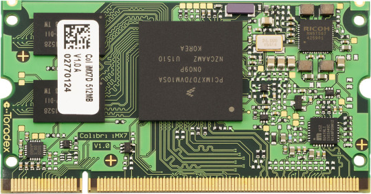
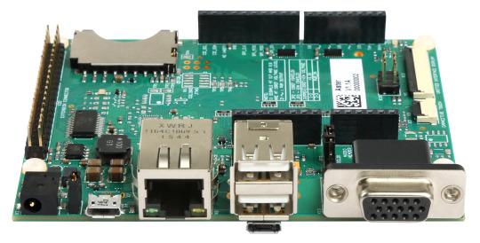
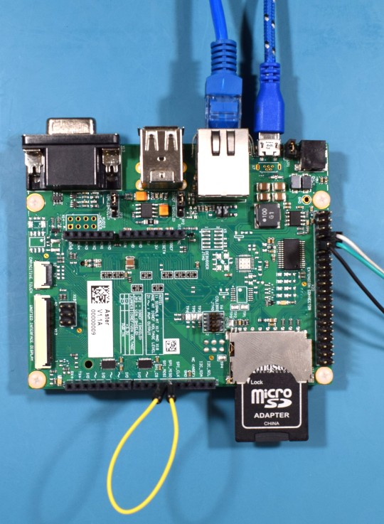
For this article, the Toradex dual core Colibri iMX7 System on Module was selected: this module is equipped with a NXP i.MX7 SoC, a dual-core ARM Cortex-A7 core plus an ARM Cortex-M4 core, with CPU clock of 1GHz for the A7 and 200MHz for the M4, plus 512MB of flash memory and 512MB of RAM. The module is presented in the image below:
The Aster has been chosen as the carrier board. It is a new release from Toradex that makes life easier for those who are developing a new project. This carrier board has the standard Arduino shields connector, allowing developers to use the various Arduino shields prototyping modules available off-the-shelf in the market to reduce their design time.
In addition to the Arduino shield, a connector with the same Raspberry Pi pinout is also available, allowing the use of modules developed for this hardware, facilitating not only the prototyping of new designs, but also the transition from proofs-of-concept to scalable and industrial quality and life-time guaranteed hardware like Toradex.
Setting up the environment
The examples presented in this article were developed on a Linux host machine. All the code for Cortex-M is based on Makefile and Cmake. To compile the examples, just install a few packages and correctly configure the toolchain.
We recommend the linaro toolchain version 4.9 2015 Q3. After downloading the tar package from the link here, extract it as below:
tar xjf ~/Downloads/gcc-arm-none-eabi-4_9-2015q3-20150921-linux.tar.bz2
Since the toolchain generates 32-bit binaries, install the 32-bit version of libc and libncurse. For Ubuntu, the commands are:
sudo dpkg --add-architecture i386 sudo apt-get update sudo apt-get install libc6:i386 libncurses5:i386
Now it is time to test the toolchain:
~/gcc-arm-none-eabi-4_9-2015q3/bin/arm-none-eabi-gcc --version arm-none-eabi-gcc (GNU Tools for ARM Embedded Processors) 4.9.3 20150529 (release) [ARM/embedded-4_9-branch revision 227977] Copyright (C) 2014 Free Software Foundation, Inc. This is free software; see the source for copying conditions. There is NO warranty; not even for MERCHANTABILITY or FITNESS FOR A PARTICULAR PURPOSE.
Finally, install cmake and make:
sudo apt-get install make cmake
Downloading the example
We prepared a couple of examples to be downloaded and easily tested, they include basic "Hello, World!" to inter-core communications. Start downloading the source code repository:
$ git clone -b colibri-imx7-m4-freertos-v8 git://git.toradex.com/freertos-toradex.git freertos-colibri-imx7/ $ cd freertos-colibri-imx7/
All the source codes that we will use as reference are in this folder. The folder structure is already done to support the Colibri iMX7 and also the FreeRTOS. Inside this structure the folder that we will most use is the folder containing all the examples:
[raul@localhost freertos-colibri-imx7]$ tree -L 2 examples/imx7_colibri_m4/ examples/imx7_colibri_m4/ ├── board.c ├── board.h ├── clock_freq.c ├── clock_freq.h ├── demo_apps │ ├── blinking_imx_demo │ ├── hello_world │ ├── hello_world_ddr │ ├── hello_world_ocram │ ├── low_power_imx7d │ ├── rpmsg │ └── sema4_demo ├── driver_examples │ ├── adc_imx7d │ ├── ecspi │ ├── flexcan │ ├── gpio_imx │ ├── gpt │ ├── i2c_imx │ ├── uart_imx │ └── wdog_imx ├── gpio_pins.c ├── gpio_pins.h ├── pin_mux.c └── pin_mux.h 17 directories, 8 files [raul@localhost freertos-colibri-imx7]$
Setting up the hardware
In this article, we are not covering how to debug on Cortex-M, so we will use a UART to get the messages printed by the firmware. It is very important to understand how to set up the environment to get a productive development set. Since the Cortex-M and the Cortex-A cores share interfaces, it is necessary to know that the messages printed on the UART B will be printed by the Cortex-M firmware and the messages in the UART A will be printed by Cortex-A (U-boot and Linux).
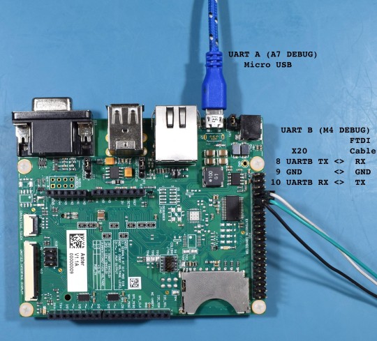
Therefore, we will use two different cables for UART A and UART B. In the case of UART A, it already has an FTDI chip on the Aster carrier board, and the connection is made by connecting it to the USB X4 connector. This connector is being used to power on the board as well as access the UART A, so when connecting it to the computer the device /dev/ttyUSBX should be recognized automatically.
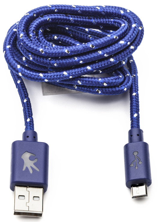
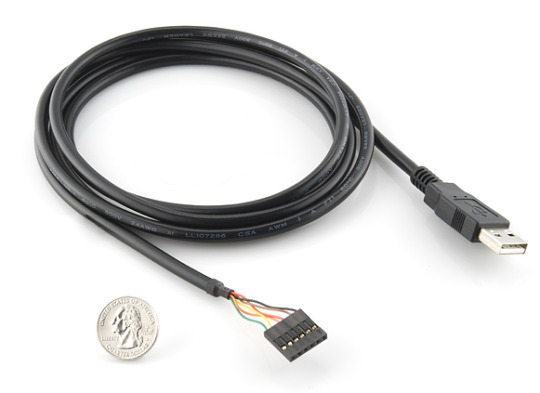
For UART B, the TX and RX pins of the Colibri iMX7 are connected in the X20 expansion header. Since there is no FTDI chip or Serial RS-232 converter for this interface, you need to use a cable popularly known as the FTDI cable. Connect the RX, TX, and ground pins of the FTDI cable to the connector X20 pins 8, 10, and 9 respectively.
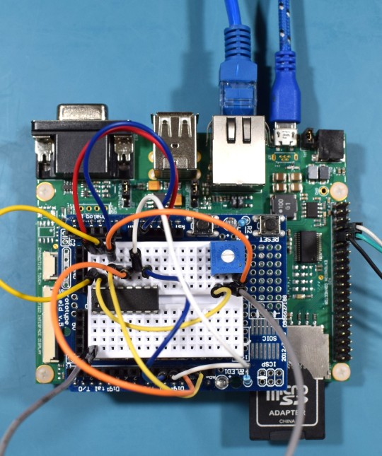
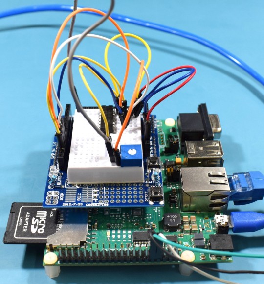
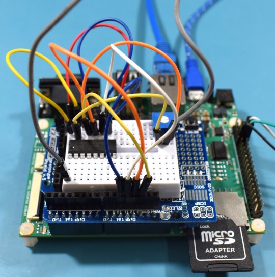
Finally, the cables must to be connected like the picture below:
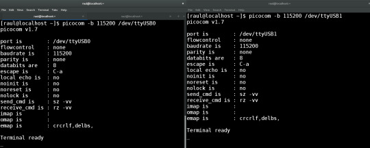
Now that the cables are properly connected, open two terminals on Linux with “picocom” and open the serial ports:
Terminal 1:
[raul@localhost ~]$ picocom -b 115200 /dev/ttyUSB0
Terminal 2:
[raul@localhost ~]$ picocom -b 115200 /dev/ttyUSB1
You may have something like the following image:
Compiling the first example
To compile the first example, go to SPI example directory:
[raul@localhost freertos-colibri-imx7]$ cd examples/imx7_colibri_m4/driver_examples/ecspi/ecspi_interrupt/master/ [raul@localhost master]$ ls armgcc hardware_init.c main.c
Note that all of the examples have the files main.c, hardware_init.c and the folder armgcc. We will not explain the source code now, just go to the directory, export the toolchain path that we downloaded and compile the example:
[raul@localhost armgcc]$ cd .. [raul@localhost master]$ cd armgcc/ [raul@localhost armgcc]$ export ARMGCC_DIR=~/gcc-arm-none-eabi-4_9-2015q3/ [raul@localhost armgcc]$ ./build_all.sh -- TOOLCHAIN_DIR: /home/raul/gcc-arm-none-eabi-4_9-2015q3/ -- BUILD_TYPE: Debug -- TOOLCHAIN_DIR: /home/raul/gcc-arm-none-eabi-4_9-2015q3/ -- BUILD_TYPE: Debug -- Could not determine Eclipse version, assuming at least 3.6 (Helios). Adjust CMAKE_ECLIPSE_VERSION if this is wrong. -- The ASM compiler identification is GNU -- Found assembler: /home/raul/gcc-arm-none-eabi-4_9-2015q3//bin/arm-none-eabi-gcc -- Configuring done -- Generating done -- Build files have been written to: /home/raul/freertos-colibri-imx7/examples/imx7_colibri_m4/driver_examples/ecspi/ecspi_interrupt/master/armgcc Scanning dependencies of target ecspi_interrupt_master_example [ 5%] Building C object CMakeFiles/ecspi_interrupt_master_example.dir/home/raul/freertos-colibri-imx7/platform/utilities/src/debug_console_imx.c.obj ... ... ... [ 94%] Building C object CMakeFiles/ecspi_interrupt_master_example.dir/home/raul/freertos-colibri-imx7/platform/drivers/src/uart_imx.c.obj [100%] Linking C executable debug/ecspi_interrupt_master_example.elf [100%] Built target ecspi_interrupt_master_example -- TOOLCHAIN_DIR: /home/raul/gcc-arm-none-eabi-4_9-2015q3/ -- BUILD_TYPE: Release -- Eclipse version is set to 3.6 (Helios). Adjust CMAKE_ECLIPSE_VERSION if this is wrong. -- Configuring done -- Generating done CMake Warning: Manually-specified variables were not used by the project: CMAKE_TOOLCHAIN_FILE -- Build files have been written to: /home/raul/freertos-colibri-imx7/examples/imx7_colibri_m4/driver_examples/ecspi/ecspi_interrupt/master/armgcc [ 5%] Building ASM object CMakeFiles/ecspi_interrupt_master_example.dir/home/raul/freertos-colibri-imx7/platform/devices/MCIMX7D/startup/gcc/startup_MCIMX7D_M4.S.obj ... ... ... [ 94%] Building C object CMakeFiles/ecspi_interrupt_master_example.dir/home/raul/freertos-colibri-imx7/platform/drivers/src/uart_imx.c.obj [100%] Linking C executable release/ecspi_interrupt_master_example.elf [100%] Built target ecspi_interrupt_master_example [raul@localhost armgcc]$ The binaries are located in the "release" directory. [raul@localhost armgcc]$ cd release/ [raul@localhost release]$ ls ecspi_interrupt_master_example.bin ecspi_interrupt_master_example.hex ecspi_interrupt_master_example.elf ecspi_interrupt_master_example.map [raul@localhost release]$
In our case, the file ".bin" is the most important. Let´s use U-boot to load it on the Cortex-M4.
Executing the firmware
To execute the firmware, it is necessary that U-boot load the binaries and run the file on the Cortex-M. It is possible to do this in different ways. My suggestion is to use a SD card (FAT32) or network. We will show the instructions to do it both ways. On one hand, keep in mind that while using the network the development occurs in a dynamic way, since it is not necessary to plug and to unplug the SD card in the board. On the other hand, to do the steps of loading by Ethernet, you need to configure a tftp server and in my case the configured folder is "/srv/tftp/". To configure tftp check the tutorial Flashing Linux Over Ethernet.
SD Card: Copy the file to the SD Card and then place it on the board:
[raul@localhost release]$ df Filesystem 1K-blocks Used Available Use% Mounted on /dev/sdb1 7780496 469540 7310956 7% /run/media/raul/DATA [raul@localhost release]$ cp ecspi_interrupt_master_example.bin /run/media/raul/DATA [raul@localhost release]$ umount /run/media/raul/DATA
Ethernet: Copy the file to the tftp server folder, plug a network cable on the board and set up a network that allows you to connect your computer to it. In my case, the board IP is 192.168.0.170 and my host computer 192.168.0.150.
[raul@localhost release]$ cp ecspi_interrupt_master_example.bin /srv/tftp/
Power on the board and on the terminal UART-A (U-boot and Linux) press any key as soon as you power it on. The idea is to stop U-boot in order to load and execute the binary.
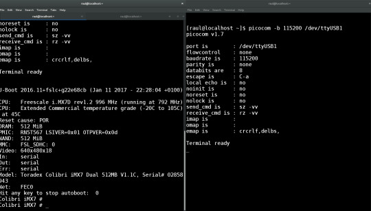
At the U-boot prompt, run the commands to load the binary:
SD Card:
Colibri iMX7 # fatload mmc 0:1 0x7F8000 ecspi_interrupt_master_example.bin reading ecspi_interrupt_master_example.bin 9956 bytes read in 20 ms (485.4 KiB/s)
Ethernet:
Colibri iMX7 # tftp 0x7F8000 ecspi_interrupt_master_example.bin Using FEC0 device TFTP from server 192.168.0.150; our IP address is 192.168.0.170 Filename 'ecspi_interrupt_master_example.bin'. Load address: 0x7f8000 Loading: ################################################## 9.7 KiB 647.5 KiB/s done Bytes transferred = 9956 (26e4 hex)
Once it is loaded, despite using SD Card or Ethernet, run the command to execute the binary that was loaded on the Cortex-M.

Colibri iMX7 # dcache flush Colibri iMX7 # bootaux 0x7F8000 ## Starting auxiliary core at 0x007F8000 ... Colibri iMX7 #
Next, you should see the Cortex-M printing the debug messages on the UART B terminal. Your screen should look like the next image.
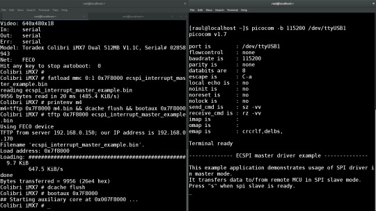
Before typing “s” in the UART B terminal, prepare a loop-back between SPI MISO and MOSI pins. Thus, it will be possible to see the communication in loop-back and not only send message but also receive data in the SPI.
-------------- ECSPI master driver example -------------- This example application demonstrates usage of SPI driver in master mode. It transfers data to/from remote MCU in SPI slave mode. Press "s" when spi slave is ready. MASTER: Transmited data: 1 : Received data: 1 MASTER: Transmited data: 2 : Received data: 2 ... ... ... MASTER: Transmited data: 19 : Received data: 19 MASTER: Transmited data: 20 : Received data: 20
Practical example - SPI
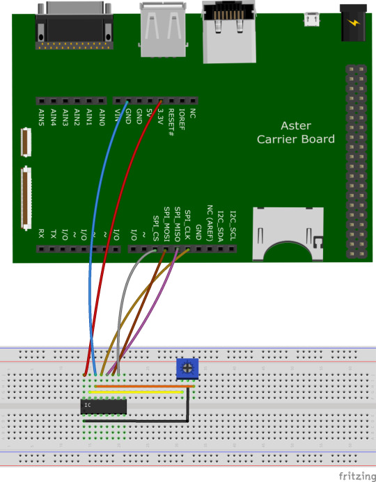
In the previous example, we only compiled and executed the code. Now, let’s modify the code to communicate via SPI with the chip MCP3008 from Microchip. This chip is a 10-bit Analog to Digital converter with 8 single ended inputs. Connect the wires to the Aster and to a breadboard as presented in the picture below:
For those who prefer to use the Eclipse IDE, it is possible to use CMake to generate Eclipse project files. The Cmake -G parameter allows to configure a “build system generator”. Make sure that “build_all.sh” specifies the “Eclipse CDT4 – Unix Makefiles” generator.
In the armgcc sample directory:
[raul@localhost armgcc]$ vi build_all.sh
#!/bin/sh cmake -DCMAKE_TOOLCHAIN_FILE="../../../../../../../tools/cmake_toolchain_files/armgcc.cmake" -G "Eclipse CDT4 - Unix Makefiles" -DCMAKE_BUILD_TYPE=Debug . make -j4 cmake -DCMAKE_TOOLCHAIN_FILE="../../../../../../../tools/cmake_toolchain_files/armgcc.cmake" -G "Eclipse CDT4 - Unix Makefiles" -DCMAKE_BUILD_TYPE=Release . make -j4
Next, execute again the “build_all.sh” script:
[raul@localhost armgcc]$ ./build_all.sh [raul@localhost armgcc]$ ls .cproject .project .cproject .project
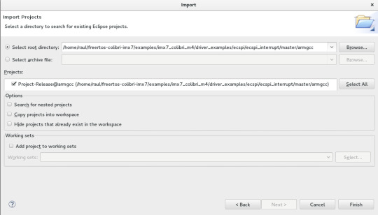
Open Eclipse and import the project: File > Import…
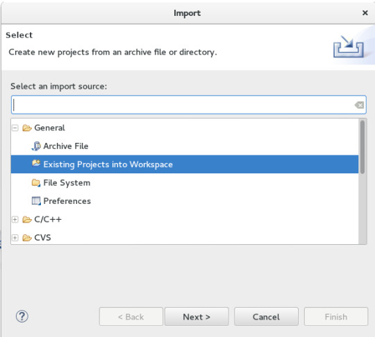
In “Select root directory”, enter the path of the “armgcc” folder of your project:
/home/raul/freertos-colibri-imx7/examples/imx7_colibri_m4/driver_examples/ecspi/ecspi_interrupt/master/armgcc
Open the file “main.c” in the directory. [TARGET] → [exec]ecspi_interrupt_master_example → Source Files
Note that the standard example is quite simple. It is important to show some points of the code to understand clearly where to look in the next examples.
int main(void) { uint8_t control_char; uint8_t i; ecspi_init_config_t ecspiMasterInitConfig = { .baudRate = 500000, .mode = ecspiMasterMode, .burstLength = ECSPI_MASTER_BURSTLENGTH, .channelSelect = BOARD_ECSPI_CHANNEL, .clockPhase = ecspiClockPhaseSecondEdge, .clockPolarity = ecspiClockPolarityActiveHigh, .ecspiAutoStart = ECSPI_MASTER_STARTMODE }; /* Hardware initialize, include RDC, CLOCK, IOMUX, ENABLE MODULE */ hardware_init(); /* Update clock frequency of this module */ ecspiMasterInitConfig.clockRate = get_ecspi_clock_freq(BOARD_ECSPI_BASEADDR); PRINTF("\n-------------- ECSPI master driver example --------------\n\n\r"); PRINTF("This example application demonstrates usage of SPI driver in master mode.\n\r"); PRINTF("It transfers data to/from remote MCU in SPI slave mode.\n\r"); /* Ecspi module initialize, include configure parameters */ ECSPI_MasterConfig(&ecspiMasterInitConfig); /* Wait slave ready, then press 's' to start communication. */ while(true) { PRINTF("Press \"s\" when spi slave is ready.\n\r"); control_char = GETCHAR(); if((control_char == 's') || (control_char == 'S')) break; } /* Send 1~20 to slave and receive data from slave */ for(i = 0; i < 20; i++) { txData[0]++; ECSPI_MasterTransfer((uint8_t*)txData, (uint8_t*)rxData, 1); while(ECSPI_MasterGetTransferStatus()); PRINTF("MASTER: Transmited data: %d \n\r", txData[0]); PRINTF(" : Received data: %d \n\n\r", rxData[0]); } while(1); }
The first item that is interesting to note is where the pin multiplexing configuration occurs. In our case, we are using the standard SPI. Right–click on the “hardware_init();” function and select “Open Declaration”
void hardware_init(void) { /* Board specific RDC settings */ BOARD_RdcInit(); /* Board specific clock settings */ BOARD_ClockInit(); /* initialize debug uart */ dbg_uart_init(); /* RDC ECSPI */ RDC_SetPdapAccess(RDC, BOARD_ECSPI_RDC_PDAP, 3 << (BOARD_DOMAIN_ID * 2), false, false); /* Select board ecspi clock derived from OSC clock(24M) */ CCM_UpdateRoot(CCM, BOARD_ECSPI_CCM_ROOT, ccmRootmuxEcspiOsc24m, 0, 0); /* Enable ecspi clock gate */ CCM_EnableRoot(CCM, BOARD_ECSPI_CCM_ROOT); CCM_ControlGate(CCM, BOARD_ECSPI_CCM_CCGR, ccmClockNeededAll); /* Configure ecspi pin IOMUX */ configure_ecspi_pins(BOARD_ECSPI_BASEADDR); }
Note that the main hardware initialization /configuration are in this function. The configuration of the SPI pins is in the last function, called “configure_ecspi_pins(BOARD_ECSPI_BASEADDR);”.
void configure_ecspi_pins(ECSPI_Type* base) { // ECSPI1 iomux configuration /* daisy chain selection */ IOMUXC_ECSPI3_MISO_SELECT_INPUT = 0; //(I2C1_SCL SODIM 90) IOMUXC_ECSPI3_MOSI_SELECT_INPUT = 0; //(I2C1_SCL SODIM 90) /* iomux */ IOMUXC_SW_MUX_CTL_PAD_I2C2_SCL = IOMUXC_SW_MUX_CTL_PAD_I2C2_SCL_MUX_MODE(3); /* ECSPI SLK */ IOMUXC_SW_MUX_CTL_PAD_I2C1_SDA = IOMUXC_SW_MUX_CTL_PAD_I2C1_SDA_MUX_MODE(3); /* ECSPI MOSI */ IOMUXC_SW_MUX_CTL_PAD_I2C1_SCL = IOMUXC_SW_MUX_CTL_PAD_I2C1_SCL_MUX_MODE(3); /* ECSPI MISO */ IOMUXC_SW_MUX_CTL_PAD_I2C2_SDA = IOMUXC_SW_MUX_CTL_PAD_I2C2_SDA_MUX_MODE(3); /* ECSPI SS0 */ /* pad control */ IOMUXC_SW_PAD_CTL_PAD_I2C2_SCL = IOMUXC_SW_PAD_CTL_PAD_I2C2_SCL_PE_MASK | IOMUXC_SW_PAD_CTL_PAD_I2C2_SCL_PS(0) | /* pull down */ IOMUXC_SW_PAD_CTL_PAD_I2C2_SCL_DSE(0) | IOMUXC_SW_PAD_CTL_PAD_I2C2_SCL_HYS_MASK; IOMUXC_SW_PAD_CTL_PAD_I2C1_SDA = IOMUXC_SW_PAD_CTL_PAD_I2C1_SDA_DSE(0) | IOMUXC_SW_PAD_CTL_PAD_I2C1_SDA_HYS_MASK; IOMUXC_SW_PAD_CTL_PAD_I2C1_SCL = IOMUXC_SW_PAD_CTL_PAD_I2C1_SCL_HYS_MASK; IOMUXC_SW_PAD_CTL_PAD_I2C2_SDA = IOMUXC_SW_PAD_CTL_PAD_I2C2_SDA_PE_MASK | IOMUXC_SW_PAD_CTL_PAD_I2C2_SDA_PS(3) | /* pull up */ IOMUXC_SW_PAD_CTL_PAD_I2C2_SDA_DSE(0) | IOMUXC_SW_PAD_CTL_PAD_I2C2_SDA_HYS_MASK; }
Another important file is “board.h”. If in the same function, you search for the definition of "BOARD_ECSPI_BASEADDR" in "configure_ecspi_pins (BOARD_ECSPI_BASEADDR);" you will see a part of the file “board.h” which sets up more things related to SPI, for example the interruption vector.
/* Colibri SPI is ECSPI3 */ #define BOARD_ECSPI_RDC_PDAP rdcPdapEcspi3 #define BOARD_ECSPI_CCM_ROOT ccmRootEcspi3 #define BOARD_ECSPI_CCM_CCGR ccmCcgrGateEcspi3 #define BOARD_ECSPI_BASEADDR ECSPI3 #define BOARD_ECSPI_CHANNEL ecspiSelectChannel0 #define BOARD_ECSPI_IRQ_NUM eCSPI3_IRQn #define BOARD_ECSPI_HANDLER eCSPI3_Handler
Returning to “main.c”, we will change the main loop to get the data from MCP3008. More specifically, we will read the channel 0 of the chip.
/* Wait slave ready, then press 's' to start communication. */ while(true) { PRINTF("Press \"s\" when spi slave is ready.\n\r"); control_char = GETCHAR(); if((control_char == 's') || (control_char == 'S')) break; }
Remove the “break” and add the code below. According the datasheet of MCP3008, the sequence “00000001 10000000 00000000”, which means the start bit, channel selection and the complement of information to form 10 bits of data, respectively.
/* Wait slave ready, then press 's' to start communication. */ while(true) { PRINTF("Press \"s\" when spi slave is ready.\n\r"); control_char = GETCHAR(); if((control_char == 's') || (control_char == 'S')) { unsigned char datatx[3]; unsigned char datarx[3]; datatx[0] = 0b00000001; // first byte transmitted -> start bit datatx[1] = 0b10000000; // second byte transmitted -> (SGL/DIF = 1, D2=D1=D0=0) datatx[2] = 0b00000000; // third byte transmitted....don't care /* SPI Read */ ECSPI_MasterTransfer((uint8_t*)&datatx[0], (uint8_t*)&datarx[0], 3); while(ECSPI_MasterGetTransferStatus()); PRINTF("Transmited data: %d \n\r", datatx[0]); PRINTF("Transmited data: %d \n\r", datatx[1]); PRINTF("Transmited data: %d \n\r", datatx[2]); PRINTF("Received data: %d \n\n\r", datarx[0]); PRINTF("Received data: %d \n\n\r", datarx[1]); PRINTF("Received data: %d \n\n\r", datarx[2]); unsigned int a2dVal = 0; a2dVal = (datarx[1]<< 8) & 0b1100000000; //merge data[1] & data[2] to get result a2dVal |= (datarx[2] & 0xff); PRINTF("data = %d \n\n\r", a2dVal); } }
After changing the example, the function “int main (void)” should look like this:
int main(void) { uint8_t control_char; uint8_t i; ecspi_init_config_t ecspiMasterInitConfig = { .baudRate = 500000, .mode = ecspiMasterMode, .burstLength = ECSPI_MASTER_BURSTLENGTH, .channelSelect = BOARD_ECSPI_CHANNEL, .clockPhase = ecspiClockPhaseSecondEdge, .clockPolarity = ecspiClockPolarityActiveHigh, .ecspiAutoStart = ECSPI_MASTER_STARTMODE }; /* Hardware initialize, include RDC, CLOCK, IOMUX, ENABLE MODULE */ hardware_init(); /* Update clock frequency of this module */ ecspiMasterInitConfig.clockRate = get_ecspi_clock_freq(BOARD_ECSPI_BASEADDR); PRINTF("\n-------------- ECSPI master driver example --------------\n\n\r"); PRINTF("This example application demonstrates usage of SPI driver in master mode.\n\r"); PRINTF("It transfers data to/from remote MCU in SPI slave mode.\n\r"); /* Ecspi module initialize, include configure parameters */ ECSPI_MasterConfig(&ecspiMasterInitConfig); /* Wait slave ready, then press 's' to start communication. */ while(true) { PRINTF("Press \"s\" when spi slave is ready.\n\r"); control_char = GETCHAR(); if((control_char == 's') || (control_char == 'S')) { unsigned char datatx[3]; unsigned char datarx[3]; datatx[0] = 0b00000001; // first byte transmitted -> start bit datatx[1] = 0b10000000; // second byte transmitted -> (SGL/DIF = 1, D2=D1=D0=0) datatx[2] = 0b00000000; // third byte transmitted....don't care /* SPI Read */ ECSPI_MasterTransfer((uint8_t*)&datatx[0], (uint8_t*)&datarx[0], 3); while(ECSPI_MasterGetTransferStatus()); PRINTF("Transmited data: %d \n\r", datatx[0]); PRINTF("Transmited data: %d \n\r", datatx[1]); PRINTF("Transmited data: %d \n\r", datatx[2]); PRINTF("Received data: %d \n\n\r", datarx[0]); PRINTF("Received data: %d \n\n\r", datarx[1]); PRINTF("Received data: %d \n\n\r", datarx[2]); unsigned int a2dVal = 0; a2dVal = (datarx[1]<< 8) & 0b1100000000; //merge data[1] & data[2] to get result a2dVal |= (datarx[2] & 0xff); PRINTF("data = %d \n\n\r", a2dVal); } } }
Recompile the binary, copy by SD Card or Ethernet according the previous example and execute the binary.
SD Card:
[raul@localhost release]$ df Filesystem 1K-blocks Used Available Use% Mounted on /dev/sdb1 7780496 469540 7310956 7% /run/media/raul/DATA [raul@localhost release]$ cp ecspi_interrupt_master_example.bin /run/media/raul/DATA [raul@localhost release]$ umount /run/media/raul/DATA
Ethernet:
[raul@localhost release]$ cp ecspi_interrupt_master_example.bin /srv/tftp/
Insert the SD card on the board or set up the network and execute the binary.
SD Card:
Colibri iMX7 # fatload mmc 0:1 0x7F8000 ecspi_interrupt_master_example.bin reading ecspi_interrupt_master_example.bin 9956 bytes read in 20 ms (485.4 KiB/s)
Ethernet:
Colibri iMX7 # tftp 0x7F8000 ecspi_interrupt_master_example.bin Using FEC0 device TFTP from server 192.168.0.150; our IP address is 192.168.0.170 Filename 'ecspi_interrupt_master_example.bin'. Load address: 0x7f8000 Loading: ################################################## 9.7 KiB 647.5 KiB/s done Bytes transferred = 9956 (26e4 hex)
Once the firmware is loaded properly, it does not matter which method you are using, run the command to execute the binary loaded on Cortex-M.
Colibri iMX7 # dcache flush Colibri iMX7 # bootaux 0x7F8000 ## Starting auxiliary core at 0x007F8000 ... Colibri iMX7 #
New with the alternate version of the code, pressing the bottom “s” on terminal UART B shows a new analog acquisition on channel 0.
Conflicts with Linux
After these U-boot commands, you may want to run the “boot” command to boot the Linux. The problem is that our example is using the UART B and the SPI. To start the Linux without problem, it is necessary to modify the device tree to tell Linux to not use these resources.
To temporarily disable UART B and SPI without changing the device tree, you can use the U-boot command below:
Colibri iMX7 # setenv fdt_fixup 'fdt addr ${fdt_addr_r} && fdt rm /soc/aips-bus@30800000/spba-bus@30800000/serial@30890000 && fdt rm /soc/aips-bus@30800000/spba-bus@30800000/ecspi@30840000' Colibri iMX7 # saveenv Saving Environment to NAND... Erasing NAND... Erasing at 0x380000 -- 100% complete. Writing to NAND... OK
More information about device tree customization is available in this article on the Toradex Developer Website
Automated deployment
In my case, I used to load the binary of Cortex-M by Ethernet. An interesting way to save time is to automate the copy of the binary to the “/dev/tftp/” directory. To do this, at the root of you project, open the file:
raul@localhost master]$ vi armgcc/CMakeLists.txt
Add the following line at the end of the file:
[raul@localhost master]$ vi armgcc/CMakeLists.txt ADD_CUSTOM_COMMAND(TARGET ${Project_Name}_Main POST_BUILD COMMAND cp ${EXECUTABLE_OUTPUT_PATH}/ecspi_interrupt_master_example.bin /srv/tftp/m4.bin)
Run the script “./build_all.sh” again and when compiling by eclipse, you should see the command running automatically on the “console”:
cp /home/raul/freertos-colibri-imx7/examples/imx7_colibri_m4/driver_examples/ecspi/ecspi_interrupt/master/armgcc/release/ecspi_interrupt_master_example.bin /srv/tftp/m4.bin
Another optimization that helped me a lot was to create the automatic rule in U-boot to load the binary:
Colibri iMX7 # setenv m4 'tftp 0x7F8000 m4.bin && dcache flush && bootaux 0x7F8000' Colibri iMX7 # setenv bootcmd 'run m4; run ubiboot; setenv fdtfile ${soc}-colibri-${fdt_board}.dtb && run distro_bootcmd;'
Now, every time you turn on the module, it will automatically load the binary and then upload Linux.
Conclusion
In this article, it was possible to learn some of the first steps to implement solutions on heterogeneous multicore processor architecture. Through two examples, we saw how to compile and run codes on the Cortex-M4 of an HMP SoC on the Colibri iMX7 Computer on Module. We also learned that the different cores inside the SoC share the peripheral interfaces, so it is necessary to understand (and plan) which peripheral will be assigned to each core.
#Toradex Blog#Embedded Application Development#Heterogeneous Multi-core#Multi-core Processors#Embedded Systems#Computer on Modules
0 notes