#microfarad
Explore tagged Tumblr posts
Visit Tumblr Blog
Explore Tumblr blogs with no restrictions, modern design and the best experience.
Last Seen Tumblr Blogs


Fun Fact
Tumblr Inc. is using 66 technologies for its website.
Text
i connected with my stepdad completely by accident today while he was trying to get a reading on a doohickey and wanted it microfarads but his thingy only read ohms and i was like ‘1 ohm is about 1,000,000 microfarads try putting it on a higher setting then convert it’ and it worked and he took me to home depot in celebration #lesbianandadultmanalliance
10 notes
·
View notes
Text
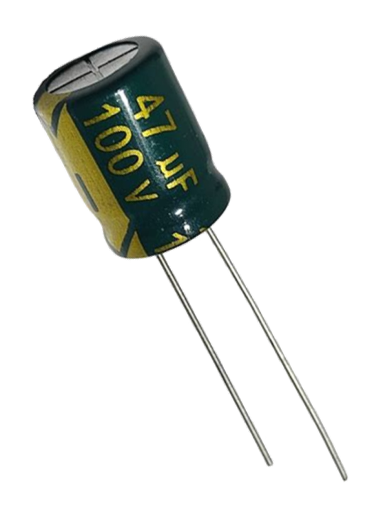

47 microfarads | 47 microFarids
8 notes
·
View notes
Text
Big is the word.
Franken-Amp is running. It sounds BIG. It is that simple. Right now it is playing Sting's Soul cages. That is a weird QSound mix, but the impression is size. It sounds BIG.
The Clarity is amazing. This is an early 1970's circuit scheme yes with tweaks by a guy who knew enough to be dangerous. I do not even have the 1,000,000 microfarads of extra capacitance plugged in. Just the 16 output transistors and a few film caps in the signal path.
This is literally night and day compared to the HK Citation 12. There is height and depth and impact. She is 4 times as powerful as the HK and the ARC. It makes a difference. All old school bipolar transistors. Well there is a handful of FETs and a tube in the preamp.
This is what I feel after a nice steak and a half bottle of a nice red wine.
This is a cool album. This is not Sting of the Police. The album is full of space and I like it. Complex and the beast untangles all the waves and gives them to you. Did I mention the Bass?
Yes the beautiful textures and warm reddish sunset light of the ARC are gone, but there is this other thing. Size and presence. Transistors have Bass gotta give them that. The kind you feel as much as hear. Oh I may have turned her up a bit, but hey its my house.
I now know I missed this. The ARC is like a pretty girl sweet and lovely. The F-A is like a tall lithe beauty who can run marathons all day in the bright sun. I write like this with wine in me. There is scotch in the cabinet. Hmmm.
Come fall I will look forward to the golden magic. She has her own charms.
I gotta play pawnshop. It has not been piped through the F-A yet.
Oh the keyboard sounds out past the left speaker. No wall there it is not a reflection. I guess QSound can work. Dint with the ARC.
Back on the solid state team droogs.
3 notes
·
View notes
Text
Disc Cap For Personal Care & Beauty By BetterCospack
A Disc Cap is a small, spherical ceramic capacitor used in digital circuits for filtering, coupling, and noise suppression. Known for reliability and stability, it offers capacitance in picofarads to microfarads. Common in energy supplies, automotive electronics, and conversation devices, disc caps make certain green circuits overall performance.
0 notes
Text
Schneider Capacitor MEHVCHDY050A44
Introducing the Aecswitchgear Schneider Capacitor MEHVCHDY050A44 - the powerhouse capacitor you need to supercharge your electrical system. Designed for high voltage applications, this capacitor is built to handle the most demanding electronics with ease.
With a capacity of 50 microfarads and a maximum voltage rating of 44 volts, this capacitor is perfect for a wide range of industrial and commercial applications. Whether you need to smooth out voltage fluctuations or store energy for quick discharge, the Schneider Capacitor MEHVCHDY050A44 has you covered.
Don't settle for subpar performance - upgrade to the Schneider Capacitor MEHVCHDY050A44 and experience the difference quality makes in your electrical system. Trust in Schneider's reputation for reliable, high-quality components and get ready to take your electronics to the next level.
0 notes
Text
True 802118 Start Capacitor(145 Mfd, 110V) | PartsFe UK
The True 802118 Start Capacitor (145 Mfd, 110V) is an essential component designed to enhance the performance of True refrigeration systems. This high-quality start capacitor provides the necessary boost to the compressor motor during startup, ensuring smooth and efficient operation. With a 145 microfarad (Mfd) capacity and a 110V rating, it is built for durability and reliability.
To keep your restaurant running smoothly, it's crucial to invest in True Start Capacitor that ensure long-lasting performance.
0 notes
Text
Factors to Consider When Picking A Motor Capacitor
Are you searching for components that offer the essential phase shift for generating the induction motors? The answer is a motor capacitor. These necessary components play a crucial role in numerous electrical systems. The proper choice of this essential component is essential for the efficient running of the motor.
Consideration of various factors
Choosing the electrical storage unit is a matter that requires serious consideration. Promote the starting performance with a Motor Capacitor. You will have to take several key factors when picking this component.
Value of capacitance
The capacitance value is one of the dominant factors one needs to consider. It indicates the extent of energy stored and the phase shift it can offer. You can measure capacitance value in microfarads. You must make a selection based on the motor's power rating. The specific needs of the application are also considered. During start-up, the Motor Capacitor offers an additional power boost.
Voltage Rating
The voltage rating of this essential component must be equal to or exceed the maximum voltage of the capacitor during operation. This is considered the line voltage of any electrical system. Selecting a component with a higher voltage rating above the standard can help you avail of a safety margin. This practical means helps in avoiding premature failure.
Temperature Rating
The temperature rating indicates its ability to stand against high temperatures. It is denoted by degrees Celsius and should be selected per the maximum operating temperature and the particular requirements of the application. Choosing a product with a higher temperature rating is essential to give you a safety margin and assist in avoiding premature failure.
Shape matters
The size and shape of the motor capacitor require careful consideration. The design must adapt to the available space. The capacitor must be mounted securely to ward off damage from vibrating motions.
Various kinds of capacitor
There are two kinds of motor capacitors. They are known as electrolytic and metalized films. The former products are generally used in applications where substantial energy storage is necessary, such as during the commencement of single-phase induction motors. The latter is used in applications that call for greater reliability, such as in the operation of single-phase induction motors.
About the pricing structure
The pricing structure of the vital component is another crucial factor to consider, but it should not be the sole aspect. A premium quality capacitor may involve a higher initial cost; however, it will perform better in the long run. Thus, investing in a superior quality product will result in a reduction of overall costs.
Taking a well-thought-out decision A prudent approach is to pay a visit to the websites of leading companies excelling in the production of film capacitors. Discover the latest technological innovations, become knowledgeable about industry trends, and explore the advantages of our premium products. Select one to meet all your capacitor needs. The focus is on a customer-centric approach. Get in touch with their customer care experts if you have queries.
0 notes
Text
Get the Best Deals on 220uF 16V Aluminum Electrolytic Capacitors and More
When it comes to building or repairing electronic circuits, capacitors play an essential role in regulating voltage, filtering signals, and smoothing power supplies. Among the many types of capacitors available, the 220uF 16V 20% 6.3X7.7mm Chip Type Aluminum Electrolytic Capacitor SMT is one of the most commonly used for various applications. Whether you're designing power supplies, audio equipment, or LED lighting systems, this component is vital for ensuring smooth and reliable circuit performance. In this article, we will explore the features of this capacitor and how you can easily find and buy it, along with other electronic components, from online stores in India.

What is a 220uF 16V 20% 6.3X7.7mm Chip Type Aluminum Electrolytic Capacitor?
The 220uF 16V 20% 6.3X7.7mm Chip Type Aluminum Electrolytic Capacitor is a high-quality, surface-mount (SMT) component used in electronic circuits to store and release electrical energy. Here's a breakdown of its key specifications:
220uF Capacitance: This indicates the capacitor's ability to store charge. With a capacitance of 220 microfarads (uF), this component can handle significant energy storage, making it ideal for filtering applications in power supplies.
16V Voltage Rating: The capacitor can handle a maximum operating voltage of 16 volts, which is ideal for low to medium-voltage circuits. It ensures that the capacitor can work efficiently without the risk of breakdown under normal operating conditions.
20% Tolerance: This specification tells you how much the actual capacitance could vary from the stated 220uF. With a 20% tolerance, the capacitor will perform within a range of ±20% of its nominal value, which is typical for many aluminum electrolytic capacitors.
6.3X7.7mm Size: The size (6.3mm x 7.7mm) makes this capacitor perfect for compact circuit boards, especially where space is limited. The chip-type design ensures that it can be surface-mounted (SMT), making it compatible with modern assembly techniques like pick-and-place machines.
Aluminum Electrolytic Construction: Aluminum electrolytic capacitors are known for their high capacitance values and relatively small size, making them an excellent choice for power supply filters, decoupling, and energy storage.
Why is This Capacitor Important?
The 220uF 16V Aluminum Electrolytic Capacitor is widely used in power supply circuits, audio equipment, lighting systems, and voltage regulation applications. Its primary role is to smooth out fluctuations in the supply voltage, ensuring stable and reliable operation of electronic devices. For example, in a power supply circuit, it helps filter out noise from the incoming AC voltage, converting it into a clean DC voltage.
It is also often used for decoupling and bypassing high-frequency noise in sensitive circuits, allowing other components to operate without interference. This versatility makes it indispensable in both commercial and DIY electronics projects.
Buy Electronic Components Online in India
Buying electronic components like the 220uF 16V Chip Type Aluminum Electrolytic Capacitor online is easier than ever, thanks to several trusted electronic components online store India catering to the growing electronics market in India. Choose some of the best online electronic stores in India where you can find this capacitor and other components without compromising on quality and your budget.
Why Shop Online for Electronic Components?
Shopping for electronic components online has several benefits, including:
Convenience: You can shop at any time of day, from the comfort of your home, and have components delivered right to your doorstep.
Access to a Wide Range of Products: Whether you're looking for a specific part like the 220uF 16V Capacitor or something more niche, online stores offer an extensive selection to suit all your needs.
Competitive Pricing: Online stores often have competitive prices and offer regular discounts and deals, allowing you to get the best value for your money.
Conclusion
The 220uF 16V 20% 6.3X7.7mm Chip Type Aluminum Electrolytic Capacitor is a vital component for numerous electronic applications, and finding it online is easy and efficient. Whether you're a seasoned engineer or a hobbyist, online platforms like Robu.in, Element14, and RS Components make sourcing these components quick, simple, and affordable. By shopping online, you gain access to a vast array of electronic components, ensuring that you always have the right parts for your projects. So, take advantage of the convenience of online shopping and elevate your electronics work to new heights today!
1 note
·
View note
Text
Lincoln 369192 370VAC 7.5uf Capacitor for Lincoln Oven Models | PartsFe
The Lincoln 369192 370VAC 7.5uf Capacitor is a critical component designed for use in Lincoln oven models, ensuring consistent and reliable performance in commercial kitchen environments. Capacitors play an essential role in electrical circuits, storing and releasing energy as needed to maintain smooth and efficient operation of the oven's motor or other electrical components.Operating at 370 volts and with a capacitance of 7.5 microfarads, this capacitor is specifically engineered to handle the demands of high-performance ovens.
#Lincoln#369192#OvenCapacitor#LincolnParts#partsfe#Partsfebuzz#Restaurantequipmentparts#restaurantowner#kitchenequipmentparts#foodserviceparts#ovenparts#icemachineparts#dishwasherparts#griddleparts
0 notes
Text
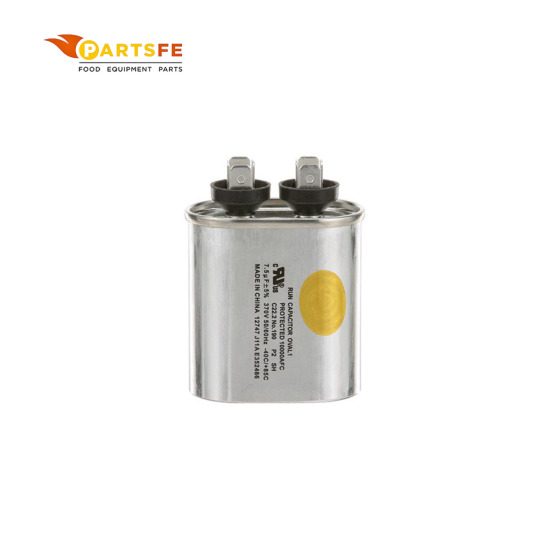
Packard TOC5 Oval Run Capacitor 5 MFD 370 Volts | HnKParts

The Packard TOC5 Oval Run Capacitor is a reliable, high-performance capacitor designed for HVAC systems and other motor applications. With a 5 MFD (microfarads) rating and 370 volts capacity, it provides efficient and stable performance. Its oval shape ensures compatibility with compact installation spaces. Built with durable materials, it offers resistance to environmental factors like heat and moisture. This capacitor enhances motor operation and prolongs the equipment’s lifespan. It's tested to meet stringent industry standards for safety and performance. Easy to install, it is ideal for replacing worn or faulty capacitors in existing systems. Manufactured by Packard, a trusted name in HVAC components.
#HnKParts#homeappliances#HnKBuzz#KitchenApplianceParts#appliacepartsonline#TOC5#OvalRunCapacitor#Packard#Packardparts
0 notes
Text
Packard TRCFD305 Volts Round Capacitor 30+5 MFD 370/440 HnKParts
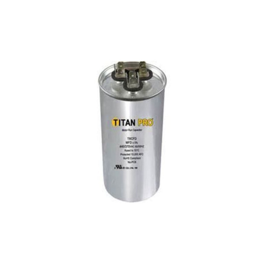
Manufacturer Name: PACKARD Product Number: TRCFD305 OEM Part Number: TRCFD305 Product Description: 30+5 Mfd 370/440V Round Ca
The Packard TRCFD305 is a reliable round capacitor designed for HVAC applications. It features a dual capacity of 30+5 MFD (Microfarads) and operates at 370/440 Volts, providing stable performance and efficient power delivery.
0 notes
Text
Packard TRCFD405 Volts Round Capacitor HnKParts

The Packard TRCFD405 Round Capacitor is a high-quality dual-run capacitor designed for HVAC systems and motor applications. It has a capacitance rating of 40+5 MFD (microfarads), offering dual functionality for running a compressor and a fan motor simultaneously. The capacitor operates efficiently across a wide voltage range, compatible with 370V to 440V systems.
Constructed with durable materials, it ensures long-lasting performance and reliability in demanding environments. The round design allows for easy installation in most standard HVAC setups. It features a compact size while providing exceptional performance to maintain optimal system functionality. This capacitor meets industry standards, ensuring safety and efficiency. Ideal for air conditioning units and other motor-driven devices.
#HnKParts#homeappliances#HnKBuzz#KitchenApplianceParts#appliacepartsonline#TRCFD405#RoundCapacitor#Packard#PackardParts
0 notes
Text
How does logic work? Decoders and Demultiplexers

Greetings to all the fans of microcontrollers and digital chips! Today, we will get acquainted with decoders and demultiplexers that allow one to expand microcontroller ports, transfer a lot of data over a few wires, create stunning lighting effects, and much more.

In the post about the CD4017 decimal counter-decoder, we've put together the running fire effect. The chip counted from zero to nine and lit the corresponding LED, which created a nice, dynamic image.

The picture becomes even better, more dynamic, and more varied if you take two CD4017s: one lighting the LEDs horizontally and the other vertically.

Today's scheme of ring running lights is different from the previous one, firstly, as the CD4017 is clocked not by the NE555 timer but by a symmetrical transistor multivibrator.

The multivibrator consists of two stages with a common emitter on transistors Q1 and Q2. These two stages are exactly the same, making the multivibrator symmetrical.
The input of each stage is connected to the output of the other through an electrolytic capacitor.
A capacitor stores electrical charge. The voltage between the plates of a capacitor is proportional to the charge (in coulombs) it has accumulated.
The larger the capacity, the more charge the capacitor needs to accumulate for the voltage across it to increase by one volt. For example, 1 microfarad means that charging a capacitor at 1 volt requires 1 microcoulomb of electricity.
Resistors limit the current. The current through a resistor equals the voltage divided by the resistance. For example, at a voltage of 1 volt, a current of 1 milliamp flows through a resistor with a resistance of 1 kilohm.
Current refers to the amount of electricity passing through a conductor, resistor, or anything else per unit of time. One milliamp is equal to one millicoulomb per second.
So, a capacitor with a capacity of 1 microfarad will charge or discharge 1 volt with a current of 1 milliamp in one millisecond. And a current of 1 milliamp will flow through a resistor with a resistance of 1 kilohm if the voltage across the resistor is 1 volt.
You can see where I'm going with this: capacitors and resistors can set the time and, accordingly, the frequency of oscillations if we have a threshold element that switches at a certain voltage value.
In our multivibrator, the role of these elements is played by transistors. For the bipolar transistor to open, current must flow through the base. And for current to flow, the voltage between the base and emitter must reach the direct drop level at the p-n junction.
Now, let's see how we have the LEDs hooked up. Each of the ten channels is designed the same way. To avoid unnecessary clutter, the diagram shows just one.
When the voltage level at the Q0 output of the CD4017 chip is high, the electrolytic capacitor C3 is quickly charged through the diode D1 to a voltage just below the voltage of the power supply. Transistor Q3 opens, and LED1 and LED2 get lit.
At the start, Q3 is in saturation mode, and the current through the LEDs is determined by the resistance of resistor R6; the voltage across it is equal to the supply voltage minus the sum of the LEDs' operating voltage and the transistor's UCE.
When the next clock pulse arrives from the multivibrator, the logical one moves to the following output of the CD4017 microcircuit. Subsequently, a logical zero appears at its output Q0. Still, capacitor C3 can't discharge through diode D1 because the diode does not conduct current in the opposite direction.
However, C3 is gradually discharged through resistor R7 by the base current Q3. This current is equal to the difference in voltage across C3 and Ube of transistor Q3 divided by the resistance R7.
As capacitor C3 discharges, the voltage across it decreases gradually, and the base current decreases accordingly. As soon as the product of the base current and the transistor current gain h21e becomes lower than the current through resistance R7, the collector current, also known as the LED current, will begin to decrease.
Thus, each LED flashes brightly and then dims down to zero when C3 discharges to voltage Ube and the transistor turns off.
Depending on the clock frequency, tuned by variable resistor R4, the LED will go out completely or continue to glow dimly until a complete counting cycle has passed, and the circuit that lights this LED has again reached a logical one.
In the video example, I've been using different color LEDs, which glowed with varying brightness levels and went out at different speeds.
youtube
The following circuit does almost the same thing but with a few quirks.

First, instead of the decimal CD4017 counter, I used binary CD4060. It is already familiar to us since I devoted a separate post.
The CD4060 has a built-in clock generator, which requires only one capacitor and two resistors to operate. Therefore, this circuit does not need a transistor multivibrator or NE555.
To get running lights, we need a decoder that, at b000 at the input, will light the zero LED, at b001—the first, at b010—the second, and so on, up to the seventh LED at 111.
The 74HC138 chip, a 3:8 binary decoder-demultiplexer, executes this function in our circuit.

Each of the 3-input AND gates processes possible combinations from 000 to 111. To handle logic zeros, inputs have inverters.
The outputs of the microcircuit are also connected through inverters. So, unlike the CD4017, where a logic one moves between ten outputs, the 74HC138 will have a low level at the output, corresponding to the input value, and the other seven outputs will be high.
Or all eight outputs could be high if the decoder is disabled. For the decoder to work, inputs ¬G0 and ¬G1 must have logic zeros, and G2 must have one.
From the counter outputs Q7, Q8, and Q9, numbers from b000 to b111 are supplied to the decoder data inputs A0, A1, and A2. And the signal from Q10 is supplied to the control input E3.
It turns out that the LED lighting cycles will alternate with empty cycles when pulses are not supplied to the LED control units, and the brightness gradually decreases.
Please note that here, we have the chip facing the diode's cathode and not the anode. Transistors use PNP structures, which are opened with a negative signal, rather than NPN, which is opened with a positive one.
The electrolytic capacitor here is charged by the base current of the transistor and discharged through the diode and the chip's output. As you can see, this upside-down scheme also works.

The program memory controller in our homemade processor unit was the 4:16 74HC154 decoder-demultiplexer. It differs from the 74HC138 in one additional input bit. This doubles the number of outputs!
Multiplexers can be cascaded. Two 74HC154s will make a 5:32 decoder. This would take four 74HC138 chips to perform the same function.

The three least significant bits, N0, N1, and N2, are equally supplied to the inputs of both decoders. And the most significant bit turns off the first decoder and turns on the second.
This means that values from b0000 to b0111 are handled by eight corresponding outputs of the first chip, and from b1000 to b1111, the second one comes in with its eight lines.
Those simple means help us perform different tasks provided by trusty logic chips.
0 notes
Text
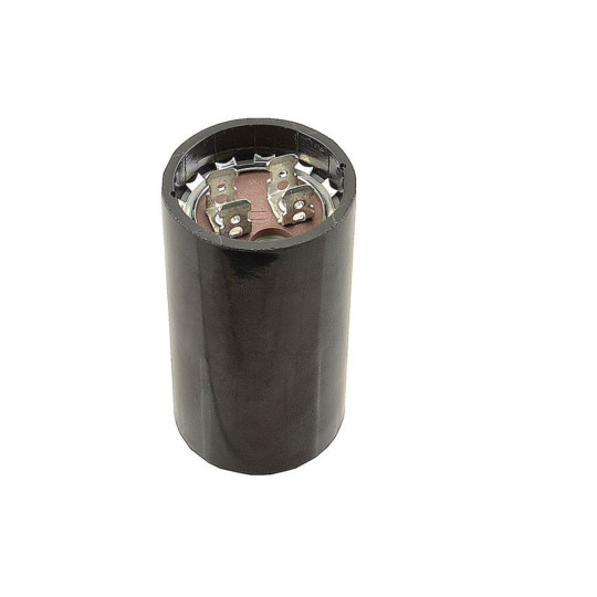
Carrier KSAHS1501AAA Hard Start Kit | PartsHnC
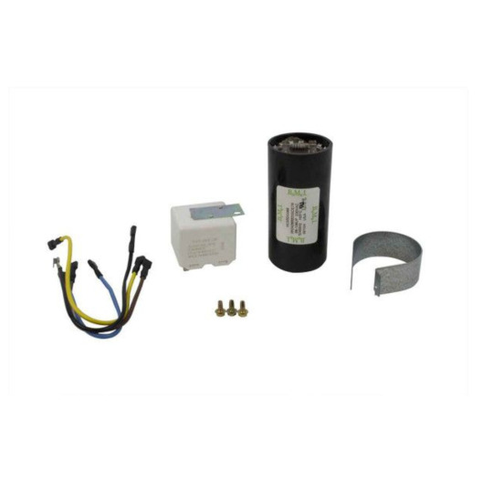
The Carrier KSAHS1501AAA Hard Start Kit is a device that assists your HVAC system during startup, especially in cold weather. It functions similarly to a little battery, giving the compressor motor a brief boost in power. The motor is able to overcome the initial surge of current needed to start up thanks to this additional boost. The hard start kit may help your HVAC system last longer and avoid issues by lessening the load on the motor and electrical system during startup. The Carrier KSAHS1501AAA has a capacitance of 98-108 microfarads and is suitable with a variety of HVAC systems.
#partshnc#airconditionerparts#hvacparts#partshncbuzz#furnaceparts#carrier#CarrierParts#KSAHS1501AAA#HardStartKit
0 notes
Text
خازن سه فاز
Power factor correction is one of the widespread applications of three-phase capacitors. Low-voltage three-phase capacitors are available in various shapes and internal structures, with diverse microfarad and kilovar capacities, as well as different brands and insulation types required in the market. Tesla Kala Company is an online reference for the sale of industrial electrical equipment, offering various types of three-phase capacitors at the best prices.
0 notes