
Statistics
We looked inside some of the posts by thegiallo-en and here's what we found interesting.
Average Info
Notes Per Post
13
Likes Per Post
13
Reblog Per Post
0
Reply Per Post
0
Time Between Posts
3 months
Number of Posts By Type
Text
17
Last Seen Tumblr Blogs


Fun Fact
If you dial 1-866-584-6757, you can leave an audio post for your followers.
Text
#Devember 2023 - Contract
I, Gianluca 'theGiallo' Alloisio, will participate to the next Devember. My Devember will be experimenting with first person character controllers, in Unity. I'm thinking about new ways to manage stamina, also in relation to stance. I promise I will program for my Devember for at least two hours every two days of the next December. I will also write a public devlog and will make the produced code publicly available on the internet. I'll try with all myself to keep my promise.
1 note
·
View note
Text
#Devember 2022 - The flu and a shaker
So, my devember started with 4 days of delay because I was on vacation. Not a big deal.
On the first day I just opened Godot and started to poke around. Exploring the editor. A lot of strange things.
I began reading the Godot introduction guide and watched a video of introduction for Unity users. I sadly had a long and strong flu, so I lost a ton of days.
I aimed to implement a button that makes a text shake. This is what I've learned in the process.
A Scene is composed out of nodes
Node is the base class, everything else is deriving from that. It has nothing. Yes, no useless transform on empty nodes. Yay!
A node can have a single script attached to it.
To add functionalities to a node one has to create a new node class, extending from some other Node class. Usually this is not required though.
The normal thing is that you add nodes, maybe base ones, and add a script to them.
You can expose things in the inspector via the export keyword.
To get another node from the inspector you have to expose a NodePath and get the node like this: onready var my_node : MyClass = get_node( that_nodepath ) as MyClass. Node the onready keyword, that makes this execute after the nodepath and scene is ready.
You can save and reuse scripts, or you can leave them unnamed and internal to the scene. To name a class you have to use class_name MyClass. If you use class MyInternalClass it would be another class, interal to your file and not the class of the script. I've lost a good hour on this.
You can wire callbacks via the inspector, except they are called signals. You can use the "Node" tab, where you'll see all signals, divided by class hierarchy. If you double click one of them a chooser window will pop-up. If you have some signals connected on a node, a wifi-like icon will appear on the scene hierarchy next to it.
Ah, every node structure you can save as a resource, and it's still called a Scene. So a Scene of Godot is like a prefab in Unity. I don't think you can have variants though, but I'm not sure. You can have local modifications of a Scene assets inside another one. So maybe its feasible to get something similar working.
Here is the video of what I managed to get working today.
In the next days I'll try to understand better the positionong and layouting of UI stuff. Fonts are another thigs that I didn't get. It seems to me that you have to make a font asset for each size you want to use.
7 notes
·
View notes
Text
#Devember 2022 - Contract
I, Gianluca ‘theGiallo’ Alloisio, will participate to the next Devember. My Devember will be learning Godot, focusing on tool building. I promise I will program for my Devember for at least an hour, every day of the next December. Well, except for the first 4 days, I’ll be on holiday. I will also write a daily public devlog here and will make the produced code publicly available on the internet. It’ll be hard, but I’ll surely enjoy the ride. I’ve heard that Godot is really nice to use for tool building. They say it has a nice GUI API. I’ve seen a lot of tools in the Godot showcase and they seem nice. Also learning a new game engine gives you another perspective on gamedev.
1 note
·
View note
Text
#Devember 2020 - Day 18 - Spectral Painter - Functions
I’ve replaced the code that was generating the images you saw, with the functions I’ve extracted. Now I keep a float matrix and don’t work converting the initial spectrogram image. Having a single line on, it has no difference.
I’ve noticed that without the image normalization the recomputed spectrogram would look like the original, but with normalization it has black values on the line, so probably they are negative values, I’m not sure there can be negative values though.
The recomputed signal has frequency that seems double of the original from the inverse STFT.
TODOs:
In the inverse STFT I should use the window I used for the STFT.
The way I manage the time shift is wrong.
I’ll have to keep a bigger spectrogram and downscale it for visualization
1 note
·
View note
Text
#Devember 2020 - Day 13 to 17 - Spectral Painter - Inverse STFT
So, I hope you are not superstitious... :D
I’ve been struggling with FFT. Studying I’ve remembered some stuff and I’ve somehow built an inverse STFT, but I’m not sure it’s correct because of the way I deal with the the time shift. I’ll have to make some more tests. For now I’ve extracted two functions that work on float matrices, but I’ve not yet tested them. I have areas of bad stuff at the start and end of the STFT, because there a part of the window is zero. I’ve tried to mitigate that with Hamming window of adaptive width, but it didn’t work. Also the STFT has a lot of bands.
0 notes
Text
#Devember 2020 - Day 12 - Spectral Painter - Hamming Window
I’ve added multiplication by a Hamming window. It’s applied in the STFT from bottom left to bottom right.
youtube
0 notes
Text
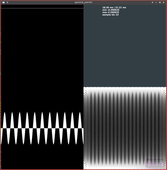
#Devember 2020 - Days 10&11 - Spectral Painter - STFT progress
I’ve made some progress on the STFT and iSTFT implementation. I had some sleepy-coding dumb bugs, even on the debug visualization. I still have to check if the STFT is correct. You can see the iSTFT of the top image below it, and it’s STFT at its right.
0 notes
Text
#Devember 2020 - Days 7,8,9 - Spectral Painter - STFT
I’ve been reading this online book about DSP for audio, trying to understand how to perform the inverse STFT correctly and how to perform it back, without loss. I’m not there yet. Sadly the compilation times and the lack of hotreload are slowing the process a lot. Also I have to compile in release mode because in debug it’s not usable. Somehow if the timer function takes more than the period, the whole program clogs up, and stops responding to interrupts.
0 notes
Text
#Devember 2020 - Day 6 - Spectral Painter - Eureka
Thanks to Howard Antares, from the JUCE forum, I’ve found the terrible bug that was haunting me.
https://forum.juce.com/t/image-pixels-y-problem/43088/11?u=thegiallo
It was an uninitialized variable due to shadowing. I’m used to have all the warnings possible turned on, but in JUCE I didn’t think about setting them, so the compiler was silent and my mind continued to switch between the meanings of the `h` variable. It was both hue and height, at the same time, depending on the place. So strange.

So now I have this correct hue-saturation plot. Hurray!
I was curious about the pattern that was being created by the uninitialization, and in theory the variable would have the value it had the previous iteration, because of the stack. I tried to initialize it manually to that value and the pattern was still there! I’ve made a shadertoy so that the whole world can benefit from my sleepy coding beautiful discovery.
https://www.shadertoy.com/view/wsGfRy
I’ve now added the flags, but there it comes... no warning. I’ve used goldbolt.org to investigate the problem and discovered that `-flto` disables the warnings about uninitialized use. Also Fahien noticed that the variable pointed by the arrow should be the uninitialized variable and not the assigned one.
https://godbolt.org/z/qnd5xh
P.S.: I’d like to highlight the fact that calling the `setPixel` function results in 7ms to write the image, versus the 0.8ms of the buffer direct access, with `-flto`.
0 notes
Text
#Devember 2020 - Day 5 - Spectral Painter - Small Refactor
I’ve done a small refactor of the image test code. I’ve added an update function so that the paint function does only the actual painting. This should make the code more readable by people trying to understand my image problem. I hope I’ll get some answers on this problem. If not, tomorrow I thinks I’ll try to build the program under windows.
0 notes
Text
#Devember 2020 - Day 3&4 - Spectral Painter - WTF
So... in these two days I’ve achieved... nothing. I did notice that the HSV image was wrong, no y changes. So I’ve investigated, and confirmed problems on y. I’ve tried many things with no result. As last resort I’ve asked on the JUCE forums. I’m really tempted to go back to my opengl code with hotreload and no portability and raw audio management. https://forum.juce.com/t/image-pixels-y-problem/43088

0 notes
Text
#Devember 2020 - Day 2 - Spectral Painter - BitmapData
I’ve introduced modifying the image via the class BitmapData and checked that the result is the same as before.
Compiling times are terrible. 6s for pretty much nothing. The Timer thing to manage the update loop seems a really bad idea... We’ll see.
0 notes
Text
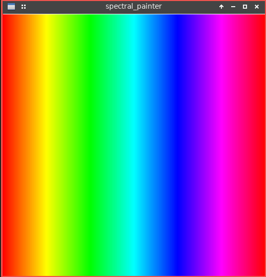
#Devember 2020 - Day 1 - Spectral Painter - Image
I’ve been reading this tutorial and I’ve added an image with an ugly pixel by pixel rendering of a Hue Saturation gradient.
https://docs.juce.com/master/tutorial_simple_fft.html
0 notes
Text
#Devember 2020 - Day 0 - Spectral Painter - Juce intro
The start is not certainly with a boost. I’m using a new library that even comes with a project management tool. I’ve downloaded the Juce build for linux and started reading the tutorials the website handily provides.
I encountered a problem with the build. I had to install libwebkit2gtk-4.0-dev because its absence was breaking the call to pkg-config and thus the build hadn’t all the system libs paths. Now it builds fine.
I normally use vim + YCM generating a compilation database via script, so right now I’m without YCM.
I was happy that Juce have a hot reload feature integrated with the tool, named Projucer. I’ve discovered that on linux is still in development. Massive sadness. And the doubt. Will I use VS on Windows? Will I code in vim or in Projucer? Will I use my code with hotreloading on linux, maybe using the library of Juce? Who knows. Anyhow, I’ve followed the tutorials up to this one https://docs.juce.com/master/tutorial_main_window.html , so basically I have the default empty audio project with an empty window. Code written: maybe 10 bytes. Here’s the repo https://bitbucket.org/theGiallo/spectral_painter/
0 notes
Text
#Devember 2020 - Contract
I, Gianluca ‘theGiallo’ Alloisio, will participate to the next Devember. My Devember will be to learn to code with Juce trying to implement Spectral Painter, a program that let’s you paint the sound spectrum, with an eye for the sound making process, pun intended. I promise I will program for my Devember for at least an hour, every day of the next December. Or at least 2h every two days. I will also write a daily public devlog and will make the produced code publicly available on the internet. I think I can keep my promise. I’ve never used Juce, so there are some risks for the target program I want to develop. At least I want to try Juce and see how I feel using it. I have nice expectations, so I’m positive. I have in mind a lot of experimentations in terms of UX that probably will remain out of this #devember. I’ll be good with having a basic painting that can play as sound.
1 note
·
View note
Text
DIYPedal_devlog[1] - low-pass filter & inverse polarity
Being that my output was noisy and low in volume I tried to investigate the low-pass filter used in Pedal-Pi. It’s a Sallen & Key 3rd order. They link this pdf with all the calculations. After skimming through it, I googled for a calculator. I found this one http://sim.okawa-denshi.jp/en/OPseikiLowkeisan.htm . I tried some values of the caps I have and finally found a combination with a cutoff at 20kHz~. I used 800Ohm and 10nF, with the couples of resistors and caps equal. To make the resistors I used a 470Ohm and a 330Ohm. After wiring the circuit up I only had 50Hz as output. It took me a lot to find out that I wired it exchanging the Vin+ with the Vin-. Probably it was oscillating, I don’t know.
Anyhow, this bug was lucky because I also found out the origin of the audio signal that could be heard with the program off. I got the polarity of the phone connector wrong. To me the best polarity was the one with the ground in tip and the channels back, in this way a mono and a stereo would have the ground in the same place and the positive polarity of the mono would be duplicated to the two stereo channels. Connecting a stereo jack to a mono output would work. I’m sure there’s a good reason why it is like it is, my knowledge is infinitesimal.
So, now my output is clearer and louder. I think I could solder the circuit on a prototype board. Oh, I also noticed that the coupling cap is shifting the output voltage, centering it near ground.
On the software side, I’ve implemented linear interpolation in the reproduction of the samples. Now it’s no more time-distorted.
I’d like to add more tracks or to try to implement some effect. To add more tracks I’d need tree more buttons per track, and to add an effect I would need a button per track, and/or one for the whole mix. I would also like to add a volume knob and a time-shift knob to each track. Obviously I’d like to add some leds to get out some feedback. I’ve being looking for how to have more outputs, and I’ve found out of expansion ICs, like MCP23017/MCP23S17. With 4 tracks I’d need 3 to 6 buttons (2 buttons for two effects, delay and reverb), and 3 to 6 leds. One led for the rec status, one for the play status and one for the recorded status. One led per effect. 24 GPIOs pins for the buttons and 10 for the leds, in a 5x5 matrix. I definitely need more pins.
1 note
·
View note
Text
DIYPedal_devlog[0] - cap&mix
Following the development during #devember 2019.
Reading the Pedal-Pi circuit I didn’t understand what C9 is doing. Thankfully with 20minutes of random googling I’ve found out what is it. It’s a coupling capacitor. It’s the exact opposite of the decoupling caps I’ve been using all over the circuit. Decoupling caps remove AC because they are in parallel with the circuit, coupling ones remove the DC because they are in series with the circuit. As simple as that. The oscilloscope shows that it cleans out some noise.

The green signal is the difference between the two, the yellow is after the cap and the red is before. The difference has the same frequency and inverted phase of the signal. I really don’t know why.
The output signal sounds very noisy. I noticed I can hear the input signal, very low, when the program isn’t running. Maybe some voltage is leaking? I hope the noise will reduce with a prototype board instead of a breadboard.
Testing I found out a bug in the recording button code, it wasn’t initializing the index. I’ve also implemented the correct mix. This was enabled by the fact that the input signal is now centered in a known Voltage: 2.048V.
1 note
·
View note