
Don't wanna be here? Send us removal request.
Statistics
We looked inside some of the posts by therealandre3000-1001 and here's what we found interesting.
Average Info
Notes Per Post
1K
Likes Per Post
820
Reblog Per Post
314
Reply Per Post
0
Time Between Posts
3 days
Number of Posts By Type
Photo
15
Text
2
Last Seen Tumblr Blogs


Fun Fact
Tumblr.com is the 103rd most visited website in the world.
Photo


PHYSICAL MODEL FINAL ENTRY *PART 2*
As I had previously mentioned, I was going to hand model the very small details; this includes the loft and its supporting structure, possibly some furniture within the living space, insulation (represented by pink sill gasket) and the technologies that run within the walls and insulation; I was considering designing the latter with some sort of wire or tubing.
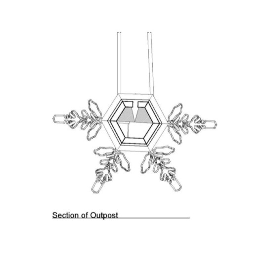
As my Outpost is symmetrical in shape, it was quite simple to manipulate into the view that I wanted to represent in my physical model. On Rhino, I had made a copy of my completed digital Outpost model and split it using a rectangular surface going through the part of the model that I didn't want to represent and used boolean split (though I realize that I could have used a clipping plane to get the section that I wanted). This allowed me to contour the shell of my Outpost as a section (at intervals of 3mm to match the thickness of the wood being used) and create an array of shapes for Illustrator to prepare for the laser cut. Finally, I scaled down the dendrites and saved them as an STL file to prepare for 3D printing. This is all how I planned to physically model my Outpost.
PICTURED:
First General Sketch During Model Planning
Detail Drawing of Wall Technology to be Represented in the Model
Initial Section of Outpost for Model Visualization
1 note
·
View note
Photo


PHYSICAL MODEL FINAL ENTRY *PART 1*
For the physical model representation of my Outpost, I had planned on completing a detail model; which has been partially created. I chose to complete a detail model due to the fact that the narrative around my Outpost included various sustainable technologies that I wanted to represent as they were not shown throughout my drawings. These were going to be represented through a section cut half way through the my model Outpost.
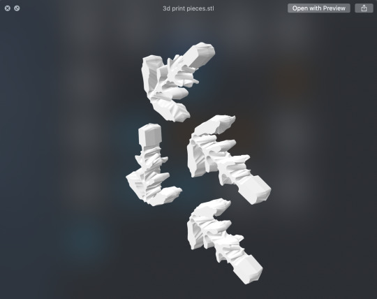
For the fabrication of my model, I chose to laser cut the main shell of my Outpost (this was completed) to provide a simple and sturdy structure to model upon. Furthermore, I was going to 3D print the four dendrites (arms of a snowflake) as they were quite complex in shape. The smaller details (furniture, insulation, sustainable technologies) were to be hand modeled so that they were represented in intricate detail.
PICTURED:
Laser Cut File Setup for Outpost Shell
STL 3D Print File of Dendrites
Front of Detail Model
Rear of Detail Model
Top of Detail Model
Close Up Interior of Detail Model
1 note
·
View note
Photo


Prep for the final. This is what i presented at today's crit. I an going to clean up my plan, add a new close up section and an elevation. In addition, here is my render progress, i need to play around with the colour and will probably do another render from a new angle that shows more of the outpost
0 notes
Photo


TOP: Axonometric Drawing of OUTPOST, Section of OUTPOST and Plan of OUTPOST
BOTTOM: Site Plan of OUTPOST and RUINS with call out showing interaction between the two.
0 notes
Photo

Finished OUTPOST hanging on my #ruins from a structural cable
1 note
·
View note

Photo


My land after 25 years and 100 years abandonment
1 note
·
View note
Photo


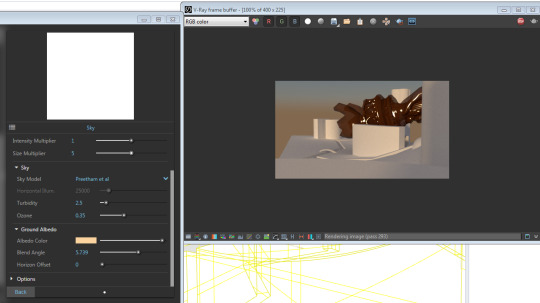
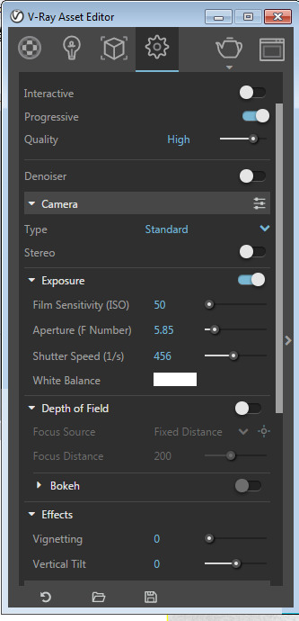
New/Updated Renders in Vray (with sun, sky and new ruins showing material) and screenshots of the Vray settings.
0 notes
Photo


AutoCAD Elevation Drawings in paper space (with and without critical red)
0 notes
Photo


Tracings oriented in model space
0 notes
Text
Task 5 Reflection
In accordance to the discussion questions mentioned in the task brief; there are many difficulties that can be faced when looking to fabricate a model. A big obstacle for me is the fact that my model is primarily undercut so the option to CNC was taken off the table (although I spoke to my TA and he inquired about CNCing in 2 plains by doing one orientation at a time and rotating the model.) I believe that i may change my mind and decide to use CNC Milling for my topography and then use laser cutting or 3D printing for the various elements that will be present on my topography.
In terms of the chosen material for my model, i may find that choosing a thicker material (in the case of laser cutting) would create less work and need less material (less $) since my topography is really tall although i know that it would look a lot better if i did an more incremental step with a thinner material. I will further explore which option best suits my model and will adapt based on the upcoming tasks.
0 notes
Photo


These screenshots show the process of setting up my model for laser cutting. As you can see, i created a minimal amount of contour lines, i did this because i wanted to make sure i understood how to do it properly before challenging myself (although if i choose to laser cut for the final, i will do smaller intervals to get a smoother stepped look for my topo). These screenshots show that i contoured my model, spread out the individual curves and projected them to the C plane. Finally i set them in a box with the proper dimensions for laser cutting and imported it into illustrator (note the red test square in the top left).
0 notes
Photo


Task 5, Process of Setting Up for 3D Print;
Before scaling my model down to the proper size of a 3D print model (75mm x 75mm x 75mm), I needed to make some changes. These changes involved deleting some of the structures that i had made or increasing their size (seen in photo 3). I did this because they were way to small, it wouldnt be worth 3D printing. On top of this i also decreased the base depth of the model to prevent using excess material when printing. Finally, as seen in the first photo, when the model was scaled down, it became distorted which i believe is due to the programs processing capabilities at that size.
0 notes
Text
Task 4 Reflective Paragraph
Task 4 was fun as it introduced the challenge of incorporating elements from my Drawing Exercise 1. I believe that i was successful in translating the ideas from my drawing titled “submerged” into my actual project. This involved the exploration of using a high elevation for the location of my outpost. My topography suited the idea as it is primarily made up two steeply pitched mountains. In addition, to follow the theme of a climate catastrophe, I incorporated cracks running through the town to represent a snowy/icy terrain. The difficulty that i faced constantly was being aware of the scale of each element as it was easy to forget that the terrain is 1kmx1km despite it looking smaller than that.
0 notes
Photo


Screenshot of my model;
I will most likely need to get rid of some detail in order to be able produce it.
0 notes
Photo


TASK 4;
Img 1 --> Topographic Model Axonometric
Img 2 --> White Clay Render (Vray)
Img3 --> Screenshot of Named Views
0 notes
Photo
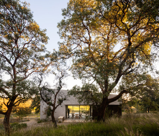
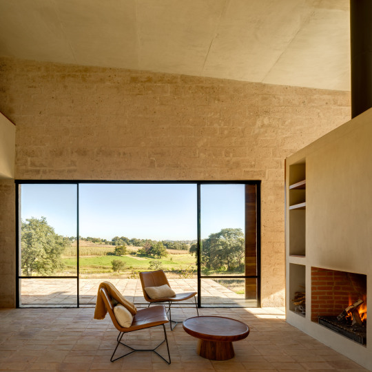
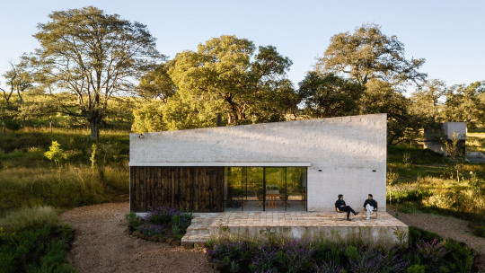
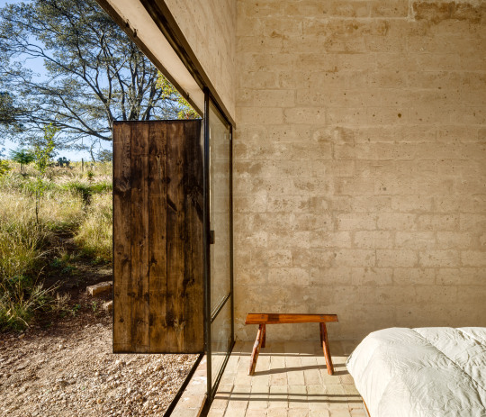
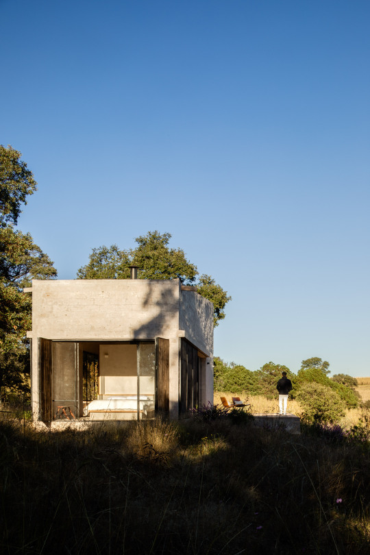
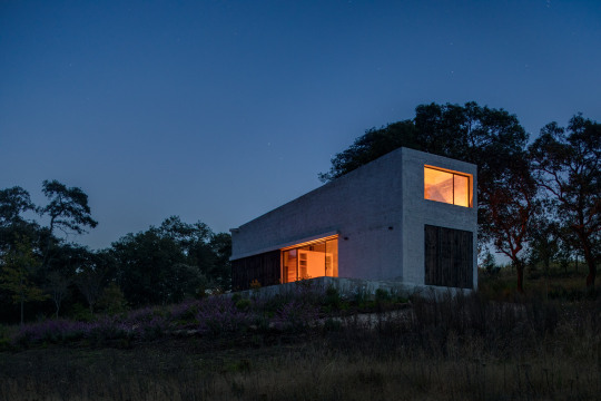
aculco house ~ ppaa arquitectos | photos © rafael gamo
1K notes
·
View notes