
thermopacblog
Thermopac
Thermopac
is the only company in the world to engineer, procure and construct the
entire Re-Refinery or treatment of used lube oil on true turnkey basis. www.thermopac.in
10 posts
Don't wanna be here? Send us removal request.
Last Seen Blogs

just-phils-things
Just Phil YT


bazarmarket
Untitled

northumbriapayrollsolutions
Northumbria Payroll Solutions

barbievoldemort
boss up thotiana
Text
Group II base oil
Group II base oil
Hydrogenation:
Hydrogenation is a generic name for treating fuels and lubricants at elevated temperatures, while in the presence of hydrogen and a catalyst.
Hydrotreating (often called hydrofinishing) and hydrocracking both are different names for hydrogenation. Hydrotreating is a non-destructive process, whereas hydrocracking is a destructive process.
This paper is restricted to the subject of conversion of PLO (Processed Lube Oil) from API Gr I to Gr II by means of Hydrotreatment process.
Hydrotreatment removes objectionable materials by selectively reacting these materials with hydrogen in a reactor at high temperatures and pressures in the presence of a catalyst. Hydrotreating removes hetero atoms and saturates carbon-carbon bonds with the result that materials such as Sulphur, nitrogen, oxygen and metals are removed; and olefinic and aromatic bonds are saturated. The process improves the colour, odor, VI and stability.
The hydrotreating process is shown schematically in Figure 1 and is described below.
The three sections of the process are:
Reaction Section
Steam Stripping Section
Vacuum Drying Section
Reaction Section:
The reaction section consists of the following equipment:
Feed/effluent exchanger
Reactor charge heater
Reactor
Reactor effluent condenser
Product separators
Recycle hydrogen compressor
Makeup hydrogen compressor
Amine scrubber
Steam Stripping Section:
The stripping section consists of:
Liquid feed vaporiser
Stripping column
Top condenser
Reflux drum
Reflux pump
Vacuum Drying Section:
The drying section consists of:
Vacuum column
Ejector or vacuum pump
Base oil transfer pump
The reactants, namely a mixture of base oil feed and high-pressure hydrogen heated to the desired temperature, enter the top of the reactor containing layers of the catalyst. As the reactants flow downward through the catalyst bed, various exothermic reactions occur and the temperature increases along the catalytic bed. The average process temperature may be reckoned at (1/3 rd of Tinlet + 2/3 rd of Toutlet).
Typical process parameters of the feed entering the reactor are; pressure 25 to 90 bar, temperature 350 to 400°C, depending upon the severity of the process and the properties of the feed.
A feed/reactor effluent exchanger preheats feed before entering the reactor charge heater. This recovers as much heat as possible from the heat of reaction.
The processes involved in hydrotreating are:
HDS: Hydro-desulfurization:
Sulphur is objectionable because it leads to catalyst poisoning; more importantly it is the
primary contributor to air pollution and the cause of corrosion in the engine.
Organic sulphur is converted to hydrogen sulphide (H₂S).
HDA: Hydro-dearomatization:
The aromatics are the most reactive components in the lube oil; and they consume large
quantities of hydrogen.
Aromatic saturation which takes place within the reactor converts some of the aromatic
compounds to naphthenes.
Removal of aromatics also improves the lubricating quality of the base oil.
HDO: Hydro-deolefining:
Olefins decreases the saturation level. Olefines also cause product fouling by the
formation of gums or insoluble materials. Hydrotreatment converts olefins to more
stable compounds and increases the saturation level.
HDN: Hydro-denitrogenation:
Nitrogen inhibits catalytic activity. Nitrogen compounds reduce the effective surface
area of the catalyst.
Organic nitrogen compounds are converted to ammonia (NH₃)
Hydrotreating employs catalysts which increase the VI.
H₂S and NH₃ formed during the desulphurization and denitrogenation reactions respectively are removed by circulating wash water before the product stream from the reactor enters the condenser in order to prevent salt formation.
A high-pressure separator separates gas from sour water (water containing H₂S + NH₃) and the recycle gas is sent to an amine scrubber to remove most of the H₂S. The hydrogen exiting the amine scrubber is compressed and recycled. A part of the nitrogen exiting the scrubber may have tobe purgedto prevent excessive hydrogen gas pressure build-up.
Efficient removal of H₂S is very important as H₂S reduces the hydrogen partial pressure and suppresses the catalyst activity.
The pressure of the vapour/liquid hydrocarbon mixture exiting the high-pressure separator is reduced in a pressure reducing station and enters a low pressure separator where the liquid hydrocarbon is separated from the gas.
Deactivation and Regeneration of Catalyst:
Depending upon the properties of the feed and operating conditions, the catalyst deactivates due to polymerization reactions and coke formation over the catalyst. The process of deactivation can partially be controlled by increasing the outlet temperature of the process steam. However, after several cycles of operation it needs to be regenerated before it is put to use again and again.
Stripping Section:
The hydrocarbon liquid exiting the reactor section is vaporized before it enters the stripping column. Steam is used as a stripping medium. The steam reduces the partial pressure of light hydrocarbons and lowers the vaporization temperature of the light hydrocarbons, which are condensed and removed from the reflux drum.
Vacuum System:
The bottom product of the stripping column is subjected to vacuum of approx. 100mbar. Water evaporates and the base oil separates out and is pumped out.
www.thermopac.in
0 notes
Text
Wiped film evaporator
The thin film evaporator (TWE), which is the heart of the re-refining plant process, is a vertical cylindrical shell enclosed in a heating jacket with an internal electrically driven rotor evenly distributing a thin layer of oil on the heated wall by means of rotating wiper blades.
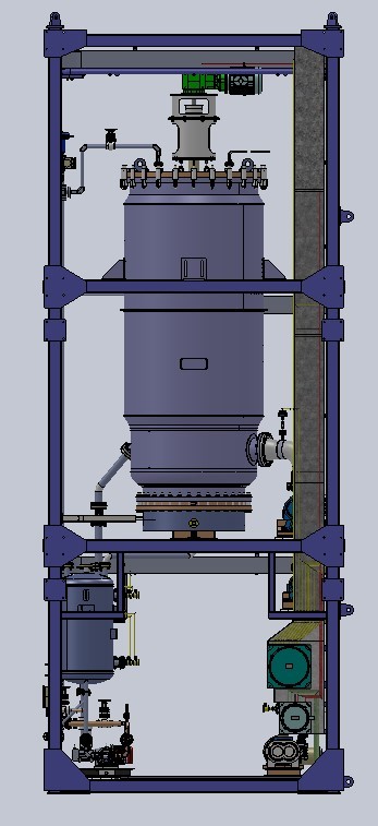
The heating medium, for example thermal oil circulates though the jacket at high temperature. The lube oil passes through the evaporator’s internal heated wall; then a rotating entrainment separator with slotted wiper spreads the feed oil which is at an optimum temperature into a uniform thin film and continuously move even highly viscous lube oil down the heated wall. At this temperature and under vacuum, vaporized lube oil passes through the entrainment separator and condenses on the internal U-bundle condenser. The internal condenser reduces pressure losses and enables achieve high vacuum. The temperatures and vacuum are automatically monitored and controlled to obtain different cuts of lube oils. The base oils thus generated continuously pass on for storage and thereafter goes for polishing/finishing. Heavy components, additives, metals and degradation products are concentrated in the bottom residue. The bottom product is automatically transferred to storage tank.
The unique features of Thermopac’s wiped/thin film evaporator are:
Short residence time.
Possibility of achieving high vacuum of the order of 0.001mbar.
High rate of heat transfer through the film.
Efficient and regenerative cleaning of the heating surfaces.
Ideally suitable for heat sensitive products
Completely indigenous technology
Manufacturing the entire skid is in house.
True turn key evaporator skid – Pre wired, pre insulated, and pre –painted along with necessary platforms and ladders.
More than 50 units are in operation
www.thermopac.in
0 notes
Text
Slop oil treatment
Slop oil treatment THERMOPAC provides a complete treatment system for any type of slop oil.
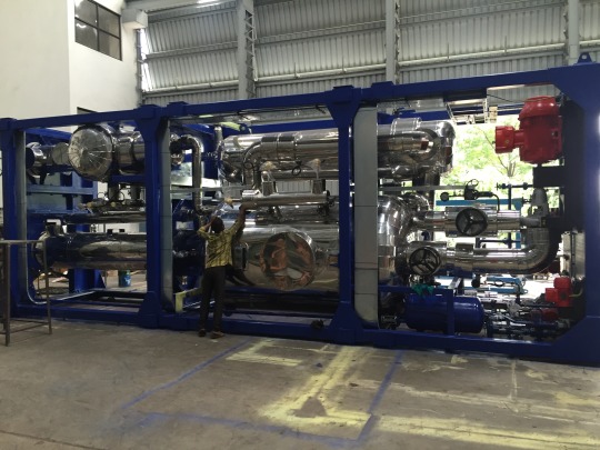
Slop oil contains hydrocarbons, solids, and water. Normally it appears as an emulsion that is not easily breakable. When the slop oil contains resins, tars, and surfactants, separation in conventional static settlers may take several hours to separate into components.
The objective of the THERMOPAC Separation System is to recycle the slop oil into the re-refining process for the recovery of light hydrocarbons, the base of oils, and finally polishing; or to mix it with normal crude oil for further processing.THERMOPAC separation system generally comprises the following steps:
Pre-treatment which involves
Heating the slop oil to reduce viscosity.
The addition of chemical emulsion breakers/demulsifiers which help to improve separation
A three phase decanter, which separates slop oil into three components consisting of oil, water and solids. This decanter is the core of the separation system
The recovered oil now complies with the standard refinery requirements and can be mixed with used lube oil for re-refining into base oils/lubricants or it can be normal crude oil for further treatment.
THERMOPAC separation system generally comprises the following steps:
Separation of residual water, light hydrocarbons such as naphtha and gas oil; and base oil plus residue from the oil recovered from the process as above
This process is carried out in a self-contained skid which houses a flash evaporator, thermal oil heat exchanger, water/naphtha condenser, decanter, Gas oil evaporator, and gas oil condenser.
The system is designed to completely dehydrate the feed and to remove light hydrocarbons such as naphtha and gas oil and deliver a mixture of fractions of light and heavy lube oils along with asphaltic residue, which can further be treated in our thin-film evaporators for recovery of various cuts of lube oil and subsequent polishing.
The plant offered by us is a fully automatic SCADA based PLC controlled plant.
www.thermopac.in
0 notes
Text
Water naphtha separator
Water naphtha separator
The vapours of water and naphtha exiting the flash evaporator are condensed in a condenser and separated in the separator taking advantage of density difference and transferred to separate tanks.

The separated naphtha and waste water are transferred intermittently to storage tanks under overall and interface level control respectively.
The separator is designed as per ASME Sec VIII Div 1
Specially Designed Water – Naptha Separator Ensures Drastic Reduction of Oil Content in to Waste water and it also improves the COD&BOD in to the Waste Water.
Overall it Reduces the Effluent Treatment Plant Load in a Big Way.
www.thermopac.in
0 notes
Text
Grease manufacturing plant
Fully Automatic Grease Plant
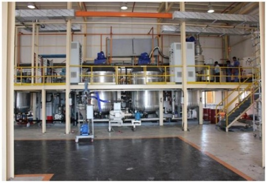
The pressure saponification kettle with an 8 bar pressure rating will allow the vessel to remain sealed until 175°C then vented to allow water to be evaporated until the maximum process temperature is reached. This will speed up the saponification process, increasing the plant’s capacity. The zoning of the jackets allow smaller batches to be made if required; also the vessel is suitable for manufacturing the entire batch if the use of the finishing kettle is not desired in a particular case.
This section of the plant is based on two 10 tonne atmospheric boiler quality plate carbon steel bodied jacketed kettles, with a fully scraped contra-rotating paddle system driven by a pair of stacked gear and motors driving concentric shafts as described below:
Charlotte Mill
The Charlotte Mill, mounted on the kettle skid, is driven by a 90KW motor and is sized to handle 6800 to 11300 kg/h of grease up to NLGI number 3. Milling gap is set by a lockable hand wheel. After the mill, the grease can be re-circulated via the kettle or discharged, either to packaging or the deaerator.
FILTER AND DEAERATOR SYSTEM
The filter is a scraped mesh unit that features a wedge wire profile that resists clogging. It is fitted with a pressure difference unit to indicate when it needs to be cleaned. The cleaning system is driven by an electric motor. The deaerator is an orifice type in-line unit that agglomerates microscopic air bubbles into larger ones that burst when the grease is discharged through a nozzle.
www.thermopac.in
0 notes
Text
Automatic blending plants
Lube Oil Blending Plant consists of:
Additive Weighing and Mixing
Base oil stock Weighing and Blending
Filling Of The Finished Lube Oils Into Containers Of Various Sizes

Lube oil blending and additive mixing is a fully automatic batch process which is performed within multiple parallel lines, each consisting of one additive weighing and mixing vessel and blender.
Every batch can be controlled by PLC and SCADA from remote operating station.
Basic feeds to the blending process are the base lube oil stocks. The blending procedure follows the prescribed formula for each product. Additives are mixed according to the precise weight prescription in order to achieve the required properties.
Lube oil blending of base oil stock and additives takes place in specially designed agitated blenders.
Finished lube oil is transferred in dedicated storage tanks and from there it’s transferred to the barrels, canisters and bottles filling.
Standard plant sizes:
50 MTD / 13,500 GPD
100 MTD / 26,000 GPD
150 MTD / 40,000 GPD
www.thermopac.in
0 notes
Text
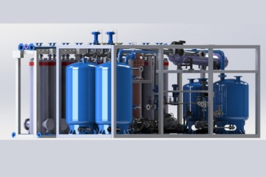
Transformer oil recycling plant
Thermopac currently manufactures Transformer Oil Regeneration equipment with sorbent and reactivation capability technology. Oil regeneration plants are of modular design with a variable number of columns and a rotating equipment skid for housing pumps, controls and control cabinet. Transformer oil treatment plants are available in different oil flow ranges from 1500 l/h up to 12 000 l/h. Oil treatment plants feature highly efficient design to achieve the most efficient dehydration, degasification and finishing Transformer Oil. Oil treatment equipment uses double stage high vacuum technology together with a variable flow to efficiently control the oil speed.
Description Of Oil Regeneration Process:
Most power equipment is using transformer oil for its di-electric properties for cooling, insulating and protecting the active parts. Transformer oils are highly refined oils that consist mainly of a mixture of hydrocarbons. Over a period of time, due to oxidation, by-products start to form in the oil. Increase in oxidation by-products result in the increase of acidity (neutralization number) and decrease the interfacial tension of the oil. At this stage, sludge starts to form, and oil starts losing its di-electric properties because it is getting old. To prevent further deterioration of oil and possible damage to the active part of the transformer, oil needs to be regenerated. Oil regeneration equipment regenerates oil in steps. At the inlet of the equipment, oil is filtered through a coarse filter to prevent any particles from entering the equipment.
It is then heated to the desired temperature to elevate the regeneration effect. After the oil has been heated, it enters the back section of the equipment. Oil is pumped through the back section which houses columns with sorbent media. It is in this section where the oil is stripped of all impurities and ageing by-products. Oil is then pumped through a vacuum breaking valve into the degassing section where it is dehydrated and degassed. Treated oil is then pumped back to the transformer oil tank by the outlet pump. After a given period, sorbent in the back section of the equipment achieves full saturation and is no longer able to regenerate oil. At this stage, the sorbent needs to be reactivated or to be restored to its original state to be able to regenerate oil.
Reactivation stage starts by draining the columns in the back section saturated oil tank. After the oil has been drained, a vacuum is created and maintained throughout the whole reactivation process in the back section. Then by selective use of heating elements on the top parts of individual columns, the reactivation process is initiated. During the process, the impurities are removed from the sorbent to restore it to its original state. This entire process can be repeated many times until the sorbent starts to lose its properties and needs to be replaced.Advantages of the Process
Environment friendly
Highly efficient with latest technology
Minimum contamination and rework
PLC Automated, with SCADA system
Skid mounted – Expandable, reduces set-up cost and time
Modular construction
STEPS OIL REGENERATION
Filtered through a coarse filter to prevent any particles from entering the equipment, it is then heated to the desired temperature to elevate the regeneration effect
After the oil has been heated, it enters the back section of the equipment. Oil is pumped through the back section which houses columns with sorbent media. It is in this section where the oil is stripped of impurities and ageing by-products
Oil is then pumped through a vacuum breaking valve into the degassing section where it is dehydrated and degassed. Treated oil is then pumped back to the transformer by the outlet pump
After a given period, sorbent in the back section of the equipment achieves full saturation and is no longer able to regenerate oil
At this stage, the sorbent needs to be reactivated (restored to its original state) to be able to regenerate oil again. Reactivation stage starts by draining the columns in the back section of saturated oil.
After the oil has been drained, a vacuum is created and maintained throughout the whole reactivation process in the back section.
Then by selective use of heating elements on the top parts of individual columns, the reactivation process is initiated. During the process, the impurities are removed from the sorbent to restore it to its original state. The off gases generated during this process are decomposed in thermal oxidizer before released to chimney.
This entire process can be repeated many times until the sorbent starts to lose its properties and needs to be replaced.
TECHNICAL CHARACTERISTICS OF OIL REGENERATION EQUIPMENT
Transformer oil regeneration process is completely automated by PLC and SCADA. Its inlet pump is a positive displacement rotary pump. The outlet pump is a centrifugally closed coupled high suction pump. For degassing the rotary vane, a vacuum pump and vacuum booster roots pump are used. For the reactivation phase, a rotary piston roots pump is used. All valves across the equipment are automatic ball valves, which are pneumatically controlled. Equipment is fully automatic, controlled by PLC logic and interfaced with a SCADA system. Numerous safety features are introduced throughout the unit to ensure the safety of the equipment as well as the operating personal. Aeration valves, overheating protection, and automatic level switches guarantee the safety of the equipment as well as its ability to identify a possible risk and to power down to prevent any accidents.
www.thermopac.in
0 notes
Text
Regenerative media based polishing systems
Drawing on decades of experience and continuous innovation, Thermopac has developed an adsorbent, RE-GENERATABALE media-based polishing system (also called finishing system) that yields high quality API I base oil without the usage of hazardous solvents or chemicals; or employing potentially hazardous hydrogen treatment plants.

It is designed as an add-on or retrofit to wiped film evaporators; it is equally applicable to other types of refineries as a final polishing stage. When retrofitted onto an existing refinery, it saves millions. Thermopac polishing system can be customized to seamlessly replace your current acid-clay system as well.
THERMOPAC Polishing System:
Improves color
Removes odour
Reduces sulphur to some extent
Reduces organic acidity
Improves oxidation stability
Has the advantage of higher yields of the finished product when compared with contemporary systems
Is the only environmental-friendly option to consumable clay and hazardous solvent extraction systems
Is an economical alternative to potentially hazardous hydrogen treatment plants involving very high pressures and temperatures; and hydrogen plants which are governed by explosive regulations.
Can be used for parallel or series type of operation.
Is a modular system.
Is available for global voltages and frequencies.
The non-consumable polishing system works on the principle of adsorption. The unpolished oil product is passed through this special media several times to get a color close to ASTM A 1 and devoid of odour. Furthermore, it results in reduction of some sulphur. Once the media gets saturated, the media undergoes reactivation at elevated temperature. After the completion of the reactivation process, it is cooled to room temperature and it is ready for reuse. The system comes in two sets of regenerative media based polishing systems; when one set is under reactivation, the other set is in polishing mode. The process loss is only the oil that is burnt during the reactivation process, which is approximately 1% of the weight of the media.
A major advantage of using this special media is that once equilibrium efficiency is obtained, no additional reduction in efficiency occurs with further regenerations.
The highest operating cost is $ 18 per ton of finished product.
The media can be used multiple times before being disposed of. It is environmental-friendly; the waste can be directly disposed of at a local landfill without any pre-treatment.The process does not suffer from any of the following drawbacks encountered in the contemporary method of solvent extraction:
The solvent extraction system needs de-aeration and inert gas blanketing to check deterioration due to oxidation and polymerization.
It requires azeotropic distillation for solvent purification.
It should be noted that none of the solvents available is perfectly selective for aromatics.
Solvent extraction by itself is not a sufficient process; it must be used in combination with other processes.
One major drawback of solvent extraction is that it removes the unsaturated compounds without conversion, reducing the overall yield.
It produces API II specification is a false statement because of its inability to remove suphur.
The health hazards of solvents like NMP need not be over emphasized. The toxic effects of NMP have been documented. When protective measures are not taken, it can cause damage to human organs such as reproductive system, eyes, nose, throat, skin and nervous system.
www.thermopac.in
0 notes
Text
Used oil refinery plant
As EPC contractor, we undertake all the activities from design, procurement, construction, commissioning to handover of the complete re-refinery plant to our esteemed customers.

Every Re-refinery plant customer has custom requirement. We implement the latest 3-D modeling tools to design every re-refinery plant. This enables us to complete the entire plant building procedure in the most accurate and timely manner. Our tested and proven Re-Refining plant process technology provides maximum yield from the used waste lube oil, Engine oil, lubricant (Black Oil) in an environmentally friendly manner. The process plants that we build for you are pre-assembled, pre-insulated, pre-wired and ready for installation and commissioning.
Oil re-refinery plant company like Thermopac has developed state-of-the-art, proprietary technology known as Thermopac-Wiped-Film-Evaporation (TWFE) to produce higher process efficiencies by minimizing bottom components and maximizing reclamation/regeneration of the useful ingredients from used lube oil. TWFE technology can extend the yields of saleable products up to 95% – 97% of the used oil feed. The high yield in the TWFE process is due to innovative equipment design and design optimizations of the process. TWFE process is acid-free, solvent-free and sludge-free. The bottom residue generated in the process can also be sold as a finished product, such as asphalt/bitumen modifier. TWFE adapts very well to feedstock variability such as used lube oils containing a high amount of water, low boilers, additives, transformer oils, turbine oils, hydraulic and synthetic oils.
Complete Automation, PLC Control and SCADA based process enables a safe and smooth plant operation with minimum manpower, in an environment-friendly manner.
With our Re-Refining plant experience of over a decade and continuous process improvements, we have a proven and established process, as described below:
Stage 1: De-Hydration and De-Gas Oil (Skid mounted package unit)
Stage 2-A: TWFE #1 to Process SN150 (Skid mounted package unit)
Stage 2-B: TWFE #2 to Process SN300 (Skid mounted package unit)
Stage 2-C: TWFE #3 to Process SN400/500 (Skid mounted package unit)
Stage 3-A: Hydrogenation (for API Group II Skid mounted package unit)
Stage 3-B: Media polishing (for API Group I Skid mounted package unit)
Stage 4: Pollution control gaseous emissions (Skid mounted package unit)
Stage 5: Effluent water treatment for water from the dehydration step
Stage 6: Packaging or bulk dispatch
THE PROCESS OUTPUT 77% of Base Oil ( SN 80, SN 150, 300, 400-500) 4% Diesel, Naphtha & Light Oil 14% of residue (Asphalt) 4% water 1% process losses
www.thermopac.in
0 notes
Text
Thermopac - The True Turnkey Used Oil Re-Refining Plant
Lube oil keeps our cars, all types of heavy vehicles and many other machines running smoothly. Once oil is used, it must be managed properly to keep it from contaminating the environment. Re-refining plants of the used oil is the most preferred way of handling used oil to protect the environment and conserve limited natural resources. Re-refined Lube oil is environmentally friendly and can be re-refined many times over for maximum savings.

Thermopac is the only company in the world to engineer, procure and construct the entire re-refinery plants of used lube oil on the true turnkey basis. We build skid mounted, continuous and automated waste free re-refining plants. Engaged in the execution of turnkey projects, we specialize in manufacturing of steam boilers, thermal fluid heaters, reactors, used oil refinery plant and other engineering products.
Since its inception in 1986 till date, Thermopac has shown tremendous growth by becoming the most reputed engineering company in India. Thermopac is the only company that is building turnkey re-refinery plants all over the world. So far we have built 31 re-refining plants in 5 different Continents.
We draw our strength from the caliber and experience of our team of engineers and highly professional and skilled manpower. Thermopac is the supporter of the merit shop concept. This assures us to complete every project on time and within budget restrictions.
Thermopac.in
#Thermopac#Used Oil Refinery Plant#Regenerative Media Based Polishing Systems#Transformer Oil Recycling Plant#Automatic Blending Plants#Water Naphtha Separator#Slop Oil Treatment#Grease Manufacturing Plant#Wiped Film Evaporator
1 note
·
View note