#3dsmax polygon modeling
Explore tagged Tumblr posts
Visit Tumblr Blog
Explore Tumblr blogs with no restrictions, modern design and the best experience.
Last Seen Tumblr Blogs


Fun Fact
Tumblr was the first site to host the blog for President Barack Obama in 2011.
Text
youtube
This is the second part of this simple chair modeling tutorial, where we will finish it by modeling the seat part and the legs.
#3dsmax#3ds max tutorials#autodesk#autodesk 3dsmax#learn 3dsmax#3dsmax furniture modeling#3dsmax modeling chair#3dsmax polygon modeling#3dsmax how to#3dsmax tips#3dsmax expert#3dsmax online courses#3dsmax online training#miled rizk#Youtube
0 notes
Text
Mehala house modeling/baking


For the past week or so I've been working on one of the main assets that will be in the spotlight of my cinematic video. Before beginning the project, I knew I wanted to have at least one house foreach of the two environment to demonstrat to the viewer how thepopulation of each area lives. To show the spirit of Mehala the green utopia, I decided to make an old hut or house of some sort with green energy elements incorporated into it. I could've chosen some modern or futuristic house instead, but, I wanted to show that even in the countryside where the lifestyle tends to be more traditional than in the city, people were still using solar and windenergy to their benefit.
I began by creating the low poly version of the model to create the detailed version based on it later on. At first, I was trying to make openings in the walls of the main structure for the windows and doors while still trying to keep a the topology clean with fully connected edge loops. I later found that to be counter-productive since I won't be working on the interior of the house, so I want to avoid having the viewer look into an empty interior. So I chose to have the walls completely shut and sticking out reflective windows as an illusion.

For the design of the house, I took multiple references as inspiration to create my own. While modeling the several parts, I kept them separate so that can have them as modular assets that could be used for multi-purposes. I still didn' want to have repetitive objects though as it would make the scene look boring. Terefore, I had to make multiple versions or copies of the same type of object with slight differences in geometry. These would be set apart even further later on in the texturing stage.
After I was done modeling, the last step was to export two versions of the scene: one with edge loops to take into ZBrush and sculpt the details on, and another to UV unwrapp in Maya and use as my low-poly model. It is worth mentioning that every time I export assets from 3dsMAX I center all objects in the 3D space, then "reset Xforms", and convert them to "editable poly". This ensures that the pivot positions are fixed and reset and prevents them from shifting positions, which makes the transfer from one software to another safer.


in ZBrush, I import the model with edge loops on the corners and Zremesh it to tesselate its topology and make it sculptable. I start by adding, macro details using either a "standard brus"h or a "clay buildup" brush while still being on a low resolution version of the model. I then turn to detailing on a smaller scale using texture specific brushes such as wood, rock, or metal for example. In the end, I use the "Decimation Master" tool to triangulate the mesh and while reducing the polygon count and still keeping the details embedded into the mesh.

After having unwrapped the low-poly model in Maya as usual, I went on to importing both versions of the assets in Substance 3D Painter to bake the details on the mesh and begin with texturing. As soon as I tried doing that, I realised that the baking was not getting done properly and there seemed to be an issue causing the mesh to have dark UV shell shapes projected onto it. To find the source of the problem I flipped through the different layers of Normals, Ambient Occlusion, Base color, etc... I found out that the problem originated from the ambient occlusion more specifically, and from experience, AO is often dependent on the geometry of the mesh rather than the UVs as it deals with shadows and the obstruction of light.
So, to compare both meshes, I decided to import them both into 3dsMAX and check if they have the same coordinates and dimensions. To my surprise, the model that was exported from ZBrush turned out to be much smaller than the ow-poly version so I had to rescale it before trying the baking another time. The second attempt was also not successful, with having AO based issues as well. It turned out that while detailing in ZBrush, some parts of the mesh had shifted too much, thus, altering the main dimensions and shape of the original mesh. I finally went back to ZBrush and slightly moved the mesh's surface in areas where the geometry values are clashing/overlapping, which solved the issue.
0 notes
Text
Story time
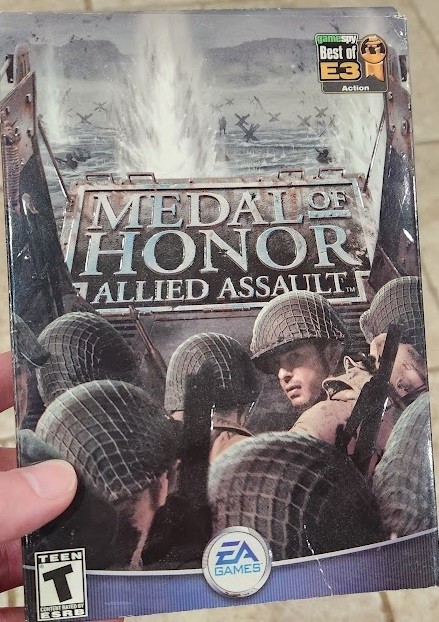
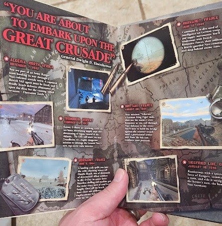
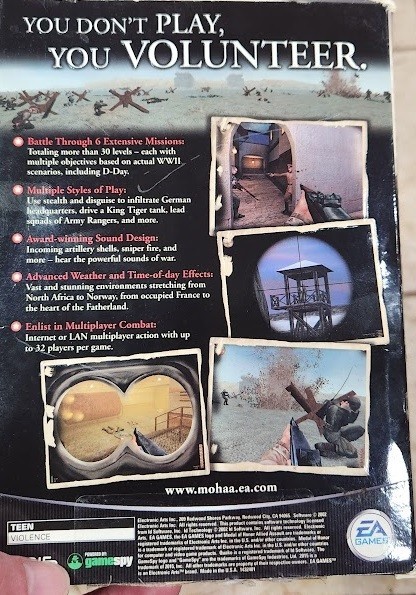
Adam brought to my attention in the last article some of the early goings on at 2015 with MOHAA, We didn't really get to sink our teeth in for some time. He reminded me that we spent time doing a prototype for a second game, which went no where. It was, Scrappy, but I did eventually get to settle in on some work. Trying to Jog my memory a bit by googling Screenshots lead me to this great walk-through Blog, which I am going to borrow some things from (Super Adventures In Gaming Blog)
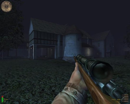
Out of the gate, when you get past the training you are treated to some of my "fine" terrain work. Couple of things about this, We had developed a dynamic terrain system for the game that was rich in features but could not draw this darned road that curved and bent like this, not without us Flagging a lot of the vertices around the road to not LOD, which subsequently created a ton of polygons and also left terrible lighting artifacts and z-fighting where the curved road and the on-the-grid terrain met.
Only an insane person, would ever go these lengths. If you're keeping up on my articles, you'll recall I had a "Blob" Method in Unreal for creating organic shapes (Story Time About Unreal PSX). That wouldn't apply here but with only convex brushes it looked different! So how do you paint an organic terrain shape using only convex brushes? The secret is in the Cylinder brush, three sided cylinder. It produced the triangle that would be the the terrain surface that you see here. That top triangle could bend and go anywhere I wanted it too, the other surfaces were simply discarded as "No draw" textures.
This would become my bugaboo during MoH:AA and later games too, I worked on many levels but every one that I was assigned to would get a framerate treatment. I wasn't a fan of sub 60hz framerate. Anyway, this guy's commentary on our 2001 game from 2013 is spot-on if not hilarious. He mentions the music early on in his walk through, which I could say was one of the highlights of all of the games I would work on. That first drop of the music, a single line of script placed and suddenly it was "Go time".
During MOHAA times, a level designer was responsible for EVERYTHING in the level. The initial focus was creating the Geometry, and then you had to make it go with some scripting. Mission 2 consisted of 3 levels (some were broken down to a,b,c sections ), they were all my work.
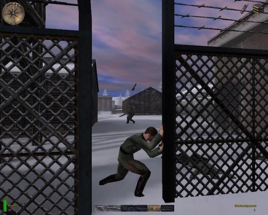
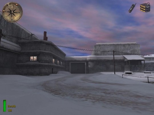
M2L1 was the infiltration of the German Sub-pen, everything was covered in snow and needed some fancy texturing work. The snow was created with No-clip so the feet could go beneath. This area was challenging the engine for me. 60Hz was hard to do on this very "open" space. Once again, insanity led me to a solution where an engineer gave me a technology that we had no term for other than "Manual Vis'ification Technology". I would connect spaces and declare them not visible for the compiler. I remember the engineer coming to my desk, with a grin when He saw how I was breaking the space up,it was a grid of blocks that would get smaller as needed for details, Dude you're basically creating an OctTree.. Huh.. k. Whatever smarty engineer dude. Not much else to say about this space other than there being a time when I wanted to try and introduce some 3dsMax modeling chops and do better rock formations, Quake3's curved patches were very limited. This game had an in-house developed Continuous LOD (Level of Detail) that fought me, On a scale as big as a rock-wall the Rocks would slowly and very visibly morph in. I ended up throwing out that Idea.
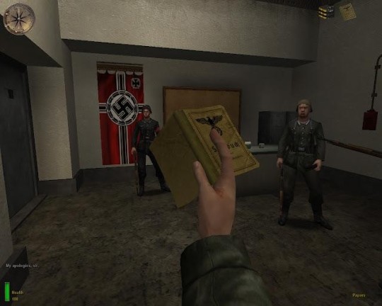
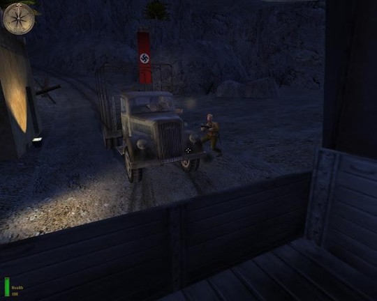
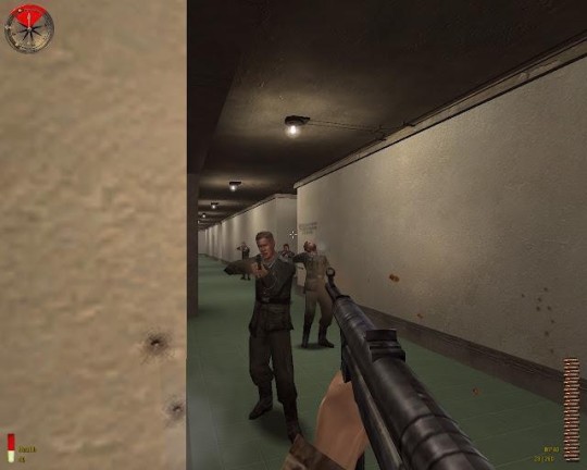
M2L2 was a place where I got to exercise some scripting, It was the first place where any kind of programming would take a foothold. Another designer had a very complex state machine setup for managing the interactions. I ended up throwing it out. All the area needed was some dudes patrolling around that would simply ask you for your papers if you got close, In certain area's you'd have to get close. If you didn't comply, the alarm would sound. It was an opportunity to set up unique scripted animations, We had these dudes at a card table, then we had a guy welding one of the docked subs. The ambient sound did the rest, there were all kinds of details in the sound to suggest more was going on in here.
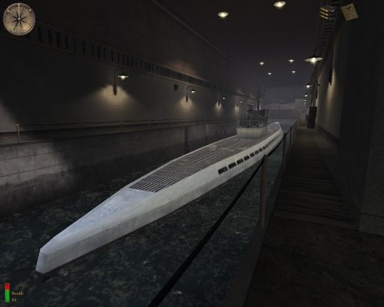
This U-boat was created for me by the art team, Unfortunately we'd hit by the fact that the engine kind of just took one point as the receptor for the lighting, Submerging the boat too much meant the whole thing turned black. There was a lot of Jiggling the boat to get it to take the light just right ( or right enough )
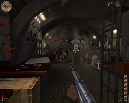
The entire inside of this boat was donated by the art team. Really cool stuff, unfortunately it was hard to move around in. Players in these games are bound to a box, We had to cheat a lot an make certain things ( the door ) non-clipping. I made sure the scripting inside here was brief.
The sub is pretty basic but I wanted to have some details and I didn't get the full attention of the art team, I don't think we had created map "Prefabs" yet, looking at those wires and things on the ceiling has me recalling a lot of painstaking copy-paste operations, and Re-wiring when I wanted to change the style. The lamps on the ceiling might just be curve brushes. Even when things were simple I wanted go hard. =)
M2L3 isn't captured here, but I remember starting in a ventilation system, We had a cockroach run away at the start that was scripted. the rest is simply set up as shoot-em-up cover is blown escape. Nothing to it.
Here we, good old YouTube! There's actually a lot more detail in this than I remember doing, it really did turn out good: Have a walk down memory lane in this walk-through of Mission 2.
youtube
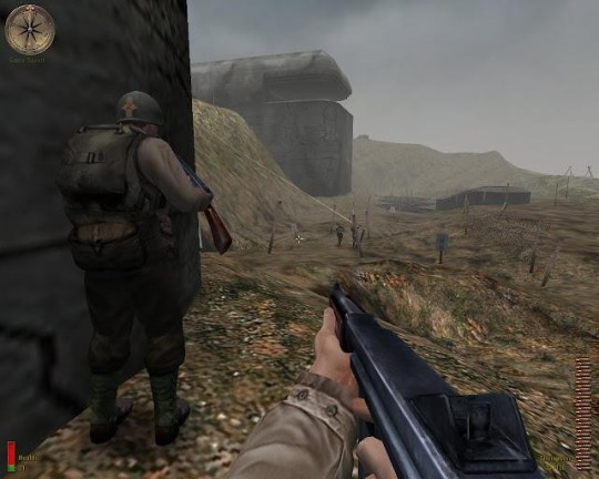
I was NOT involved with DDay, It was glorious. This is where the artists went. My first E3 had us demoing this to people in a bunker with a long line. Too be fair my memory of E3 blends with Call of Duty so I'm not sure which, but it was awesome to be the surprise hit of the show. I also remember Snoop-dogg himself walking right by. How cool!
There are other missions that I had a hand in, There were some non-technical Level Designers that I would go offer some scripting to and some missions that I would help create destroyed buildings for.
I helped with the Gas Mask sequence of this mission, Creating a timer, overlaying the gas mask, scripting the fog ( gas ).
youtube

I don't know which one's but I got involved with some of the war-torn missions and helped bust up a lot of buildings. If you see a rubble pile, there's a good chance I was in there.
I can't remember, if I was involved with Tanks, I think I may have helped with the geometry for the missions with tanks. Not to reveal too much about CoD, but tanks were my missions there so things are murky, if you remember please do chime in. I'd love to hear.
I think that's it for MOH:AA stay tune for more stories!
0 notes
Text
Assignment 5: Part 3
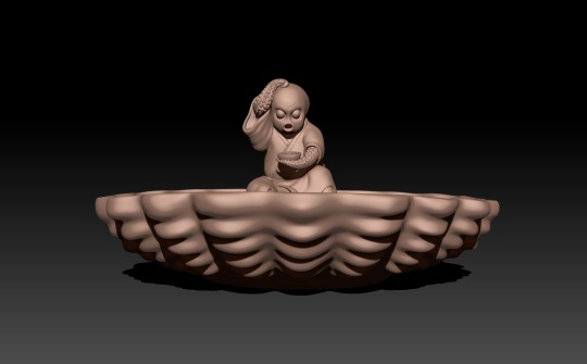
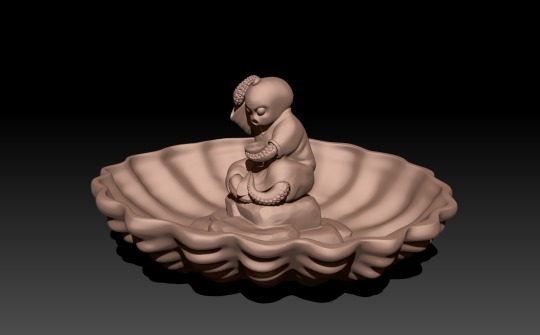
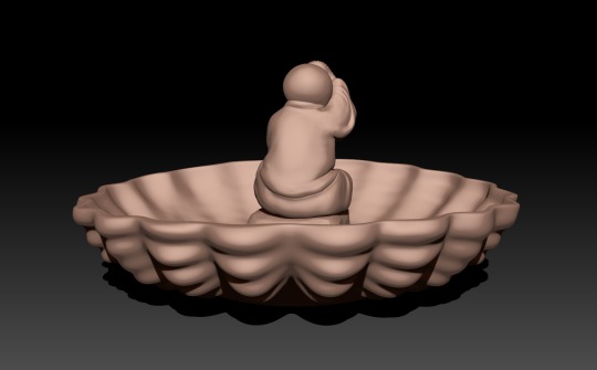
This is the last part of the 3D printing where I finalise the object I decided to create.
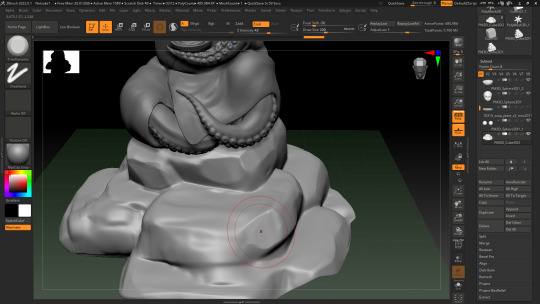
After I was done with the main Netsuke piece, I jumped into creating a base for it. I wanted it to fit the overall theme of a Japanese garden, so I made it into slabs of rock. It was my first time sculpting stylised rocks so I made sure to watch a few online videos for reference. The channel IceCrystal ART had a video which was quite helpful and straightforward (https://youtu.be/phgEOyqhDuo?si=9l7xw1p3PK3NAw6X).
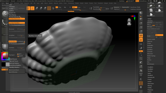
After that came the stage where I created the planter bowl. I quickly modelled it in 3dsMAX and imported it into ZBrush to add details. Then, to create wavy bumps on its sides, I used the "Standard" brush to carve into the bowl on both sides. I wanted to make sure that the brush only affects one side at a time, so I researched how to do it online. I found this video by Follygon on YouTube which introduced me to backface masking for brushes (https://youtu.be/G_pEfhDqtZY).
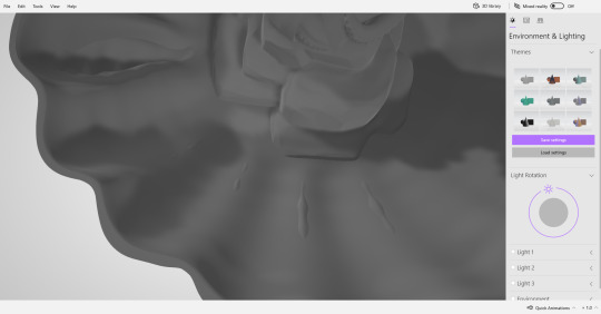
At first, the backface masking was very useful, but I later realised that using it had a potentially bad effect. Both sides of the surface no longer had a connection and were independent, this caused them to overlap in places where the surface had been pushed too far in or out. Unfortunately, this was not clearly visible inside of ZBrush and I only realised it had happened after exporting the object later on. I ended up fixing it afterwards by using the backface mask again and pushing the mesh in the opposite direction in places where it overlaps.
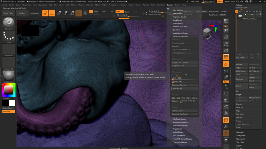
The final step was to get the sculpt ready to be exported. Meanwhile, the subtools were too high in polygon number so I had to reduce them somehow. For that, I remembered a tool that was discussed during class, which is ZBrush's "Decimation Master". It turned out to be relatively easy to use as I only had to do two steps: preprocess all the subtools first, then decimate second. What this allowed me to do is reduce the number of polygons while keeping the sculpted details intact by transforming the mesh into triangular faces. In the end, I exported the entire object as an STL file which is ready for printing.
Sources:
IceCrystal ART (2019). How to Create Stylized Rock for Games Speed Art / 3ds Max / ZBrush / Substance Painter. YouTube [online video] Available at: https://youtu.be/phgEOyqhDuo
Follygon (2019). How To Use Backface Masking In ZBrush. Youtube [online video] Available at: https://youtu.be/G_pEfhDqtZY
0 notes
Text
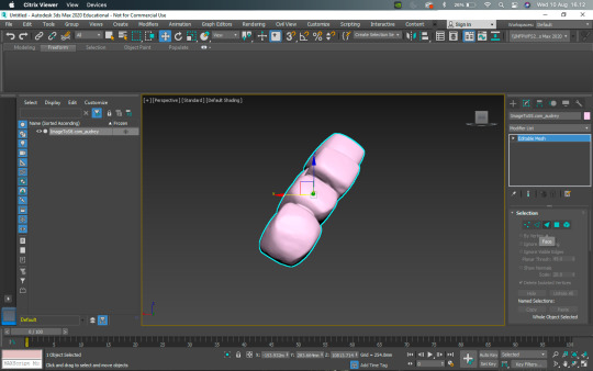
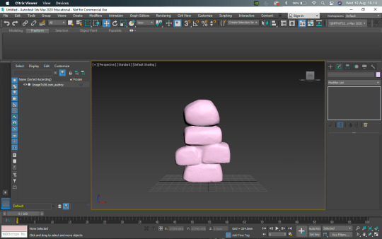
Monday, it’s a school night. Means I have to teach my class tonight. This is a project I have them do early on. It’s all about taking primitive modeling to actual complex mesh modeling.
1 note
·
View note
Photo
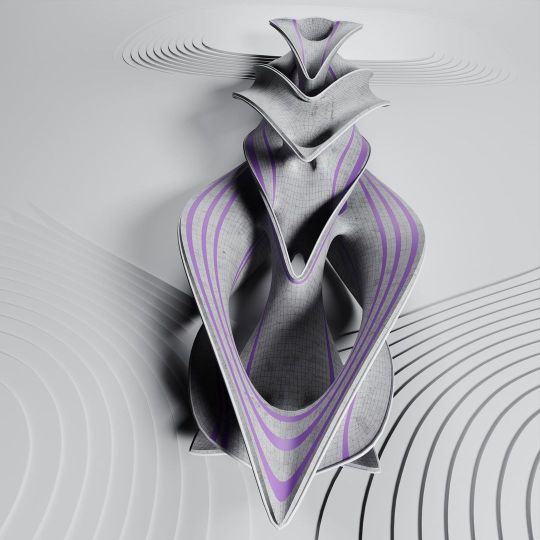
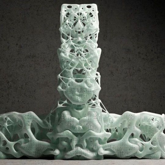
Contorted Compositions V2.0 webinar: Grasshopper + 3ds Max with @amir.h.fakhrghasemi - If you can’t attend the live date and time you will still get access to the recording by registering! - Register Now, link in bio or: https://designmorphine.com/education/contorted-compositions-v2-0 - Contorted Compositions V2.0 intends to introduce a set of form-finding methods that are based on Minimal Surface concept and its combination with Polygon Modeling methods with Rhinoceros, Grasshopper, and 3ds Max. Simulation of Forces and Data Management tools in both 3Ds Max and Grasshopper are another part of this teaching webinar. Through the combination of modeling tools in these two software we will attain the necessary freedom in the customization of mesh typology. . . . . . . #rhino3d #grasshopper3d #parametricart #3dmodeling #architecture #parametric #3dsmax #autodesk #math #building (at 𝓣𝓱𝒆 𝓤𝒏𝒊𝓿𝒆𝒓𝒔𝒆) https://www.instagram.com/p/CjighREJMGM/?igshid=NGJjMDIxMWI=
#rhino3d#grasshopper3d#parametricart#3dmodeling#architecture#parametric#3dsmax#autodesk#math#building
9 notes
·
View notes
Text
Week 8 Studio Tutorial – Digital Iteration
Pre-class work
The pre-class work, involving a case study on Andrew Simpson's model-making process, was really insightful especially considering I was working on my own models and iterations in my studio class.
Whilst I knew of the importance of model-making in communicating a product's form, this video really highlighted key ideas such as the perceived value of a product, it's materiality and the ergonomics of the product through allowing consumer-object interactions within this process.
With this insight, in my next project, I'll definitely spend less time working on pen and paper and try to jump into 'low-fidelity' model-making as soon as possible, which consists of creating quick sketch models which may consider the form and feel in the hand, as well as reviewing dimensionality, aesthetics etc. Constructing many low-fidelity models will allow me to explore my options and therefore progress onto more refined ideas quicker. These can then be represented in more limited 'high-fidelity' models, which really focus on the exact dimensions, functionality and perhaps look into materiality and finish. I'm keen to bring this new knowledge into my next design project!
In-class work: Part 1 - Introduction to 3Dsmax
Navigating a new program was definitely a difficult and time-consuming process. I found that at first, even trying to perform the most basic tasks such as locating where a certain tool was or even trying to rotate or move an object wasn't straightforward. I found myself constantly searching up where certain commands and tools that were being described in the week 8 tutorial document or a Youtube video were, as my interfaced differed from the one being shown or described. Although tedious, this process of familiarity of navigation is necessary to make any progress. I definitely found that watching the video tutorials provided, as well as some additional videos on Youtube, is a superior method of learning in comparison to just reading written tutorial notes.
I found that setting up the gizmos and pivot points was really confusing, as I wasn't sure if I had correctly set it up according to the instructions. Reflecting upon these confusions and difficulties, I think the only way forward is more practice, more research, and more clarification. I think next time, if we're given any in-class time to work on CAD, I'll definitely try to use my time more efficiently so I can ask questions in real time, where my queries can be clarified straight away, rather than trying to find the right keywords or names of certain functions to Google.
Overcoming the frustration of learning a new program is definitely an experience I'll need to get used to in this degree, as each program will have it's own nuances which I will need to be patient with and work through as an industrial designer.
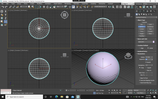
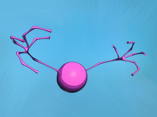
Once I had set up everything and created my sphere, I began to play around with the modifiers as instructed. This gave me insight into the possibilities of 3Dsmax and I was excited at the prospects of what I could do in future if I were to use it more frequently.


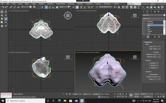

Playing around, I could definitely see how the program may be used for furniture or object design CAD purposes, and I began to try to create forms that were familiar, such as an hourglass shape, a bar of soap and a form that could potentially be a stand or table. One really interesting modifier that I got really exciting results from was the noise modifier with the fractal toggle on. As seen in the bottom left picture, I was able to create an organ-like, almost feotal, alien form. I loved how organic and detailed this result was compared to some of the other modifiers I'd used. I'll definitely be revisiting this modifier to see what interesting creations can come out of it.
Part 2 - Polygon Modelling

Delving into polygon modelling definitely gave me a better idea of the capabilities and possibilities of 3Dsmax. The youtube tutorials were really helpful as they introduced key tools of extruding, chamfering, cloning, bridging and NURMS. Following the tutorial of creating the train-station seat using NURMS really gave me insight into the process of using this tool. It is a trial-and-error type process involving going back-and-forth and seeing what little changes using differing tools creates the best end-result. Knowing this, I've gathered that I should give myself ample time to explore whilst creating something on a digital platform, especially one in which I'm unfamiliar with and the tools seemingly neverending.
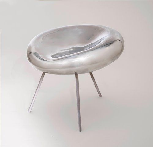
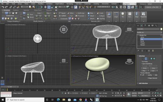
When moving onto the next step, I challenged myself to make a chair I had found on Pinterest. I used a range of tools, including modifying simple primitives from part 1, as well as utilising the polygon modelling skills I had acquired in part 2. Whilst not an exact replica, I was happy I had enough control in 3Dsmax to create an intentional form, involving an organic seat form with a divet and incline and rounded chair legs of a certain angle.
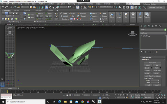


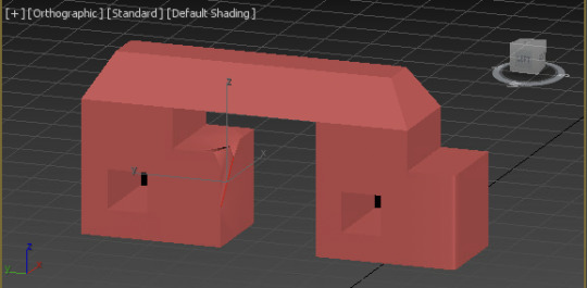
Next, I decided to create a more hard-edged, geometric form. I wanted to create an abstract sculpture of sorts, which may be featured on the street or in an exhibition. Rather than replicating, here I was able to let myself really go to extremes with the tools and experiment and see what forms could come out of it.
This was a very challenging, frustrating yet really rewarding a valuable week for me. CAD and digital programs are always more daunting for me as someone who sees myself as a more creative and hands-on rather than a tech-savvy person. I'm happy with my overall progress and the outcomes which came from it, and next time I'll definitely know to give myself lots of time to explore a new program, as it is a very time and energy consuming process.
14 notes
·
View notes
Text
Week 9 - Digital Modelling 2
Pre-class: Cup design
Andrew repeatedly points out the importance of physical models in the design process - different models can be used to explore different properties of the design (e.g. surface finish, size, weight, overall geometry, material choices, etc) but this exploration cannot be substituted with digital models. Digital models can be used to rapidly ideate and iterate with regards to form and function, but a 3D printed model gives only limited insight into the user experience of the design. On thing that I had not put that much thought into (and was highlighted in both the videos on the razer and the cup) was the importance of the weight (and distribution of that weight) of a product and how that alters our perception of other characteristics of an object.
For example with my faceted bottle design (from last week) the sharp edges when experienced in a model made from foam are an interesting tactile experience - the sharp edges are noticeable, but the bottle actually sits in your hand quite comfortably.

However, the same edges would be far too sharp and would make the bottle uncomfortable to hold if it the model was instead made of glass. The mass of the glass in combination with those sharp edges would concentrate force wherever those edges press against your palm and fingers, resulting in a bottle which can only be held for a short time (if any!) before it would become uncomfortable to hold and would therefore need to be put down or at minimum, have your grip adjusted.
Digital model clean-up and modification
The first step in the whole process (re-meshing the scanned file into the quad mesh) turned out to the be most painful part of all. I use Rhino 6, which of course does not have QuadRemesh available as a function (it was introduced in Rhino 7 much to my chagrin).
Rhino 6 has some mesh tools which I tried to use in order to achieve the same outcome, I tried to reduce the polygon count using the "Reducemesh" command, but the problem remained that the point cloud mesh from the 3D scan still resulted in a mesh with discrete facets, instead of an interpolation of the points, which would have resulted in a file which would not produce desirable results even if further processed in 3DSMax.

Rhino 6 is obviously underdeveloped in this regard which meant I had to go through the whole rigmarole of installing Rhino 7 on a virtual machine (It's only a trial version and I've had it brick Rhino 6 on my computer before, so no thanks).
One upside to having tried (and failed) to convert the scan of the bottle into a quad-mesh on Rhino 6 first was that I spent a fair bit of time reading the documentation for Rhino 6 & 7 and consequently have a better understanding of mesh modelling which actually helps me understand why I had some problems in previous projects using mesh models.

Quadremesh in Rhino 7 achieved the desired outcome so it was on to 3DSMax to further process the file as per Robs demonstration.

Following importing the .3DS file it was a pretty quick process to get the model ready for digital processing. Firstly it was important to correctly orientate and then relocate the origin to the centre-base of the model. this makes the model easier to manipulate (e.g. if you go to rotate the bottle it behaves as expected and doesn't randomly fly off on you). I'd be curious to know why the origin isn't automatically placed in the centre of the scanned mass by the scanning software, but ultimately it is of little consequence, and the process of cajoling it into place is simple enough if a touch tedious.

The polyedit modifier was then utilised to relax some of the imperfections in the mesh and make it smoother, in particular there were a couple of divets on the base which needed correcting. This was a really useful tool to employ and I will doubtless do this many times in the future as I am very rarely satisfied with how the scans I have made of objects in the pas have turned out, and manually manipulating the in rhino is tedious and ultimately doesn't produce a satisfying end product, even if you sink hours into it.

Making the bottle symmetrical in both the X and Y axis greatly improved it's overall appearance, though the mesh (or original bottle that was scanned?) had noticeable 'weld lines' no matter where I located the planes of symmetry - I even went back and played around with the origin and axis orientation relative to the model, but it only helped a bit. If anyone has any tricks for this I'd love to hear them!

My work-around for reducing the visual impact of / eliminating the weld lines was to go over the weld lines with the relaxing brush with the aim of flattening out the creases. I'm quite pleased with the result overall and would be curious what other methods people have found. A tool which applies a global smoothing to the model would be ideal, but it would need granular control and the ability to vary the extent of smoothing in each axis individually in order for it to not turn everything into perfect spheres. If I had a 3D scan of a cow I could theoretically produce a (previously only) metaphorical spherical cow, though how useful that would be in the real world is questionable :P

The final thing to do was to scale the bottle in the Z axis to make it 5mm taller as per the tutorial. This was easy to achieve the FFD modifier and the scale tool acting only on the z axis.

3D printing this model would be annoying given it has no neck for the cap to sit on top of. I will modify the bottle to include this feature before I send it to print proper.
10 notes
·
View notes
Text
Week 8 Studio Tutorial- Digital iteration
This week we started to learn how to move from physical to digital models, we visited MCIC and observed how to use a machine to scan our Object into a 3d model, we also learned about different modifiers in class, some of the common ones are Noise Skew, Ripple, Squeeze, Stretch and bend, Twist, Melt and taper, FFD and symmetry, FFD, twist and taper.
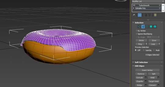
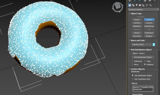
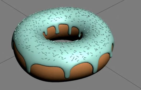
For 3dmax, I tried to follow an online tutorial video to learn how to make a Donut to get similar to 3dsmax. I’m trying to write down the steps here. To start off first create a torus as a donut, then go to modify tab and type in the data and select the modifier with Noise. It is helpful to rename the object and change the colour for easy understanding. Then add an edit poly modifier and then choose the polygon selection type, select the polygons on top of the donut, press Alt and the icon which is cross with arrowhead and shift to move up as the chocolate on the top. Then back to edit poly modifier and choose the vertex selection type that the vertex moves along the edge to make it look more realistic. Select two of both and choose TurboSmooth in order to smooth out the mesh. With the icing selected add a shell modifier on top of the edit poly modifier and type in the value. Go back to the edit poly modifier and choose the edge selection type then hold down shift and draw the edge down to create a new polygon. Click on the toggle end result button to see the mesh with all the modifiers applied to it to make it look more accurate choose the vertex selection.
Final, Create a new ChamgerCy for decorating the donut, rotate it to 90 degrees on the x-axis, go to the utilities panel and click on the reset form button and reset selected, choose the new modifier Bend to make it more real. Select compound objects from the command panel and click on scatter, increase the number and change the size. Then the doughnut is done! ( BUT the most sadness this is in the final step I forgot to cut the screen and save it :( )


13 notes
·
View notes
Text
WEEK 9 : PREPARING FOR 3D PRINTING
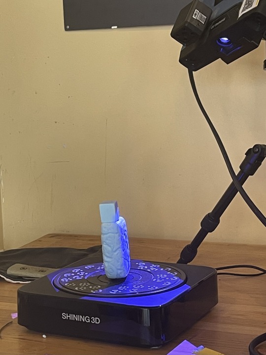
PART 1 : SCANNING THE MODEL
For this week's activity it integrates our perfume bottle foam models from studio class. we began by getting a 3d scan of the physical foam bottle. some problems that occurred at this stage were the scanner could not pick up some sections of the bottle due to lack of light thus the bottle would need to be scanned from different angles then we eventually got a 3d scan in stl file.


PART 2: IMPORTING THE FILE AND REORIENTING
I began by importing my STL file into rhino and used the Quad Remesh function to simplify the object this allows us to edit the object easier as a simpler polygon and one obstacle i faced was the laptop i was using was not strong enough to process the original STL file this step aided on that too as i was able to manipulate it easier.
I proceeded to open the file into 3DS Max to reorient the object and position it for printing since the original file put it in an awkward position and away from the planes. some difficulty i had in this area was opening the file in 3dsmax since i was not familiar with the interface.
PART 3: PREPARING IN CURA
After repositioning the model, the next step was to import it into Cura to further prepare it for 3D printing. the steps to take were to position it in such a way that it would be more stable to print to reduce risk of failure since 3D printers can be quite temperamental, i found that laying the object on the biggest side on the printing bed would be more beneficial also would also reduce the printing time since it would require less supports. i also reduced the infill of the object to 10% since that would be sufficient structure for a sample model.


This week's activity greatly sparked my interest and It was interesting to see how 3D scanning worked ad how it could eventually lead to a physical model and I hope to further explore this part of model making.
5 notes
·
View notes
Text
Week 9 - Preparing a 3d scan for printing
The design process is a really important component when managing time and expenses when producing a design. During the design process of prototyping, many important decisions are made. The materiality, colours, textures, manufacturing techniques, finishes, and how the product is marketed and who is marketed towards.
Rapid prototyping is also a way to save funds, instead of using expensive materials and techniques. Examples like additive 3d printing prototyping and subtractive CNC prototypes.
Step 1: 3D-scanning


Step 2: Quadify scan on rhino


I imported the 3d scan STL file to rhino and applied the Quad Remesh tool to the form. This tool gave a much simpler polygon structure compared to the initial triangular mesh which would be useful in 3Dsmax, a polygon modelling software.

Triangular mesh Polygon mesh


Comparing the initial triangular structure to a more organised polygon structure.
Step 3: Orientating scan on 3Dsmax
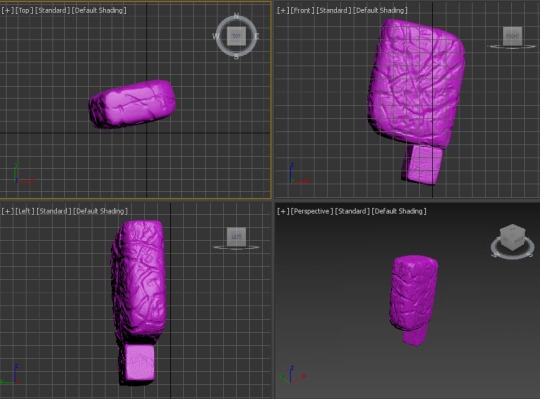

After quadifying the scan, I imported the file to 3Dsmax and rotated the shape using the rotate tool, align tool, and move tool. I orientated the bottle in the orientation I would like considering the origin, and the X, Y, and Z axes and saved the file for printing.
Since my model has purposefully placed dents, I did not find the need to smooth out any dents. I wanted to maintain the organic aesthetic of the bottle to evoke the serene emotion
This part was a little bit frustrating working with Citrix again it was not as fast as the demonstration during the tutorial. I was very thankful the tutorial was recorded and I was to work through the remeshing stage at my own pace without interrupting the tutor or fellow students.
Step 4: Uploading to Cura


I then uploaded the file to Cura to print, however for some reason the scan was still not in the correct orientation. Perhaps have done some wrong or did not save properly. I was thankful that Cura also had a rotating and alignment tool as well.
When setting up the print settings, I was advised to print with a lower infill percentage to help with the cost and time required. I was also advised to add some support around the curved edge on the base to ensure it print successfully.
This week was full of new processes that I was not familiar with, it was very fun, interesting, and enriching to learn about the processes that are performed in the industry on a smaller scale.
4 notes
·
View notes
Text
youtube
This is a two-part tutorial on how to model a simple chair. You will learn multiple tools and techniques regarding polygon modeling. In this first part, we will model the upper part.
#3dsmax#3ds max tutorials#3dsmax tutorials#autodesk 3dsmax#autodesk#learn 3ds max#3dsmax modeling#3dsmax chair 3d#3dsmax furniture modeling#3dsmax online course#3dsmax polygon modeling#3dsmax online training#3dsmax expert#Youtube
0 notes
Text
Van Modelling 2


At this second stage, is when I started encountering issues with the topology of the first asset that I am creating. The first thing that I noticed is that when modeling organic hard surface objects there's a need to smoothen sharp edges. In my case, it is to prevent the vehicle from looking too boxy or two-dimentional. At first, I was using the "chamfer" tool that I often employ to create organic-looking curves in specified corners of my model.
Soon after, I realised that changing the geometry of an object in selected areas only would result in having an uneven number of edges, and would mess up the balance of my topology. As a result, I ended up having Tris instead of Quads which are usually the desired types of polygons. The direct effect of this on my model was a clear distortion in the surface of the van. Even with smoothing groups activated, the curves were looking odd depending on the reflection of the light. To fix that, I inserted extra edges and vertices where needed to complete the broken edge loops.


After I was done modeling, I imported the asset as an FBX file into Autodesk Maya to begin unwrapping the UVs. I usually prefer doing this step in Maya rather than 3dsMAX as I find the UI and UV tools more user-friendly. the first thing that I noticed is that some parts of my model were getting triangulated after getting imported into the software. This isn't necessarily a huge issue as real-time rendering engines such as UE5 triangulate meshes anyway. Although, the issue was that triangulated meshes make it are more difficult to unwrap since they mess up the structure of loops predefined in the modeling stage.
I had t find the reason behind this so I can fix the issue. I meticulously began inspecting the model in 3dsMAX part by part, and I ended up discovering way too many overlapping edges and faces that resulted from the constant alteration of the mesh. I made sure to delete all unnecessary ones and welded all disconnected vertices together to eliminate any gaps. I also found some N-Gons here and there which were also created a result of the same factors. These were easily fixed by connecting vertices and adding edges as well, and that's how the mesh was no longer getting triangulated after importing it in Maya.
0 notes
Text
Assignment 5: Part 1
In this blog post, I am going to break down my process of creating the 3D asset for the "3D Printing" assignment. When the project brief was first released I was very excited for it as I had never tried building something for 3D printing before. In the beginning, I was thinking about creating a miniature diorama type of environment including a main monument for example. But as I had already modelled similar assets in the past, I wanted to give myself a different type of task that would be a bit more challenging. I had created a sword before which turned out kind of cartoonish and not as realistic-looking as I would've liked. For this reason, I really wanted to give myself the chance to experiment with sculpting techniques. This is when I remembered about a project idea which I had started before but ended up abandoning. It's the Leviathan Axe from the game God of War (2018).
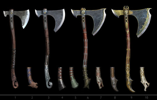
Since the game had many versions of the axe throughout, I decided not to focus on recreating a specific one, and to focus on the process instead. I was heavily influenced by another artist's rendition which I found on Sketchfab. So, I began by inspecting the 3D model by Alex Chuchvaga, and trying to decipher the way the axe was created. I realised that the axe was created as a game asset, so the detailing was made through texturing and using a normal map and was baked on a low-poly model. In my case, I needed to have the details sculpted on the model itself instead, so I took a slightly different approach to the workflow.
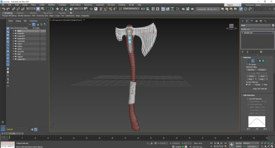
The first step was to create the base model inside of 3dsMAX. I began by blocking out the main shape and adding segment iterations to manipulate the volume. Before exporting it as an FBX file I had too keep in mind to add extra segment loops on the edges that I'd like to preserve. To test out if the model would retain its shape in ZBrush after increasing the subdivision level, I used the "Turbosmooth" modifier inside of 3dsMAX which increases the polygon count.
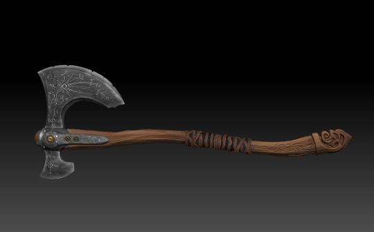
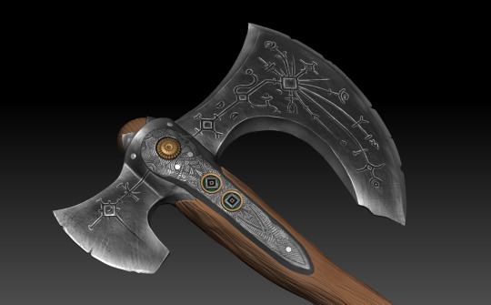
Once ready, I exported the FBX file and imported it into ZBrush. The first step was to "Zremesh" the model to begin sculpting. The main brushes I used are "Clay build up" to create the engraving on the wooden part of the axe, and "Trim Dynamic" for the sharp ends of the blade. I then used the "Dam Standard" brush to create the engraved shapes on the metal parts, as well as, chippings to simulate some more realism and make the blade's edge look slightly dull and worn out. The last step was to create more textural deformations to make sure both parts of the axe are recognized as distinct materials. For the haft, I used an alpha shape which turned out perfect to paint the wooden texture in 3D. As for the head, I searched online for special brushes for metal and rock. I ended up using...which I found on...
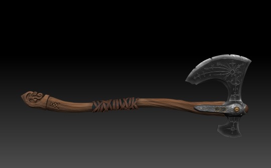
Since the axe was meant to be 3D printed, there was no use in texturing the model, therefore there was no need to UV unwrap the model. Nonetheless, I really wanted to see what the axe would look like as a polished game asset, so, I decided to hand-paint it quickly using the "Polypaint" feature inside of ZBrush.
I am proud of the results I ended up with overall, but more importantly, this assignment acted as a great opportunity for me to practice my sculpting skills without having to worry about extreme optimization or clean UV unwrapping.
Sources:
sketchfab.com. (2019). Leviathan Axe - 3D model by AlexChuchvaga. [online] Available at: https://sketchfab.com/3d-models/leviathan-axe-ef5dc2b5d99d43108e61029ec916b35e
0 notes
Text
Week 8 Exercise Reflection
Week 8 was an exciting and painful week for me. I especially like learning modeling software, such as rhino in the last term. I like the precision and logic I feel in the process of software modeling.
This week, we had a preliminary understanding of some basic operations of 3dsmax, a modeling software. Including understanding the composition of UI, modeling logic and the use of some tools, etc. I think I have done a good job in understanding software modeling methods. In class and Autodesk tutorial, I have learned a lot about how to make efficiently in 3dsmax. I can express what I imagine through the skills I have learned. In this regard, I think I am successful.
Difficulties
But this process is still very difficult, because I have been very familiar with the operation of rhinoceros before. In a sense, I have formed a modeling idea in rhinoceros. Therefore, in 3dsmax, there are many operations that are very different from what I expected, including rotation, translation, viewing angle, etc. During the production process, I felt a little uncomfortable. But after a period of trying and learning, I can naturally be handy.
But another problem has been bothering me: the system compatibility is not high. In my acess, both resolution and system response speed make the whole modeling process very bumpy. Including the incompatibility of magic mouse and the incompatibility of ALT and option on the keyboard. In addition, due to the performance of GPU and the way similar to simulator operation, display problems often occur. But under such difficult conditions, I still successfully completed the exploration of some models.

1. Modifier: love
In task 1, I start with a sphere and superimpose different modifiers on it. Including bend, stretch, squeeze, taper, etc. Then, I used symmetry to turn the original model into two staggered together to form such a heart.

2. Edit polygon: sofa? chair?
Later, when I began to study some methods and techniques about edit polygon. This method allows us to modify the appearance properties of a shape in some detail. Including extrusion, chamfer, etc. Through these methods, I designed a chair (or a single sofa?) with a base integrated with an armrest.At the handrail, I use the chamfer adjustment to make the overall visual feeling more comfortable.
Interesting fact: the angle of this sofa chair and cushion is based on the famous Barcelona chair.

3. Pratical attempt
When I was basically familiar with these techniques, I tried to create my Olay moisturizer bottle in this. The final product looks okay. But I think the shape formed by adjusting the surface is not smooth enough, whether using edit polygon or edit mesh, but I have no other solution.

If I had a chance to do this. The best thing is to prepare a Windows computer lol. If it is really difficult to achieve, I think it is necessary to prepare a mouse with a scroll.
After I finished this exercise, I thought about it. I think learning modeling software is a very important thing, because it provides a new idea for us to express our ideas. Due to the development of science and technology, all kinds of modeling software are good communication tools. It is more intuitive and comprehensive than painting; it is more convenient than a physical model. But we can't rely entirely on it. Our communication skills must be comprehensive.
12 notes
·
View notes
Photo
Contorted Compositions V2.0 webinar: Grasshopper + 3ds Max with @amir.h.fakhrghasemi - If you can’t attend the live date and time you will still get access to the recording by registering! - Register Now, link in bio or: https://designmorphine.com/education/contorted-compositions-v2-0 - Contorted Compositions V2.0 intends to introduce a set of form-finding methods that are based on Minimal Surface concept and its combination with Polygon Modeling methods with Rhinoceros, Grasshopper, and 3ds Max. Simulation of Forces and Data Management tools in both 3Ds Max and Grasshopper are another part of this teaching webinar. Through the combination of modeling tools in these two software we will attain the necessary freedom in the customization of mesh typology. . . . . . . #rhino3d #grasshopper3d #parametricart #3dmodeling #architecture #parametric #3dsmax #autodesk #math #building (at 𝓣𝓱𝒆 𝓤𝒏𝒊𝓿𝒆𝒓𝒔𝒆) https://www.instagram.com/p/CkBbx9WpF9B/?igshid=NGJjMDIxMWI=
#rhino3d#grasshopper3d#parametricart#3dmodeling#architecture#parametric#3dsmax#autodesk#math#building
7 notes
·
View notes