#ASME Sec. VIII Div. 1
Explore tagged Tumblr posts
Visit Tumblr Blog
Explore Tumblr blogs with no restrictions, modern design and the best experience.
Last Seen Tumblr Blogs


Fun Fact
130K people were victims of a chain letter scam that affected Tumblr in May 2011.
Text
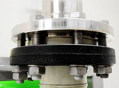
Little P.Eng.: Delivering Expert Flange Design Services as per ASME Sec. VIII Div. 1, Appendix 2
Flange design plays a critical role in ensuring the safety and integrity of pressure vessels and piping systems. When it comes to designing flanges as per ASME (American Society of Mechanical Engineers) Sec. VIII Div. 1, Appendix 2 for ABSA (Alberta Boilers Safety Association) submission, it is crucial to rely on the expertise of a trusted engineering firm. Little P.Eng. is a renowned engineering consultancy that specializes in providing comprehensive flange design services. With their deep understanding of ASME codes and regulations, they are well-equipped to assist clients in meeting ABSA requirements with precision and efficiency.
Expertise in ASME Sec. VIII Div. 1, Appendix 2:
Little P.Eng. prides itself on its extensive knowledge and experience in working with ASME codes, specifically Section VIII Division 1. Appendix 2 of this section provides detailed guidelines for flange design, including bolt loads, gasket constants, and allowable flange stresses. Compliance with these specifications is crucial for ensuring the safety and reliability of pressure vessels. The team at Little P.Eng. possesses a deep understanding of this appendix and keeps up-to-date with the latest revisions, ensuring their designs meet the most current standards.
Accurate and Reliable Flange Design:
When it comes to flange design, precision is paramount. Little P.Eng. employs highly skilled engineers who utilize advanced design software and tools to accurately calculate critical parameters such as bolt loads, gasket constants, and flange stresses. By leveraging their expertise and cutting-edge technology, they deliver robust and reliable designs that are tailored to each client's specific requirements. The team ensures that the design complies with the ASME code, meeting the stringent ABSA submission criteria.
Compliance with ABSA Requirements:
ABSA, as the regulatory authority in Alberta, Canada, mandates strict adherence to safety standards for pressure vessels and piping systems. Little P.Eng. understands the ABSA submission process and the specific requirements that need to be met. Their flange design services are customized to comply with ABSA regulations, enabling clients to obtain necessary approvals for their projects. By engaging Little P.Eng., clients can rest assured that their flange designs will undergo a thorough review process, meeting all ABSA requirements.
Collaborative Approach and Client Satisfaction:
Conclusion:
When it comes to flange design services as per ASME Sec. VIII Div. 1, Appendix 2 for ABSA submission, Little P.Eng. stands out as a reliable and experienced engineering firm. Their deep understanding of ASME codes, expertise in flange design, and commitment to compliance with ABSA requirements make them the go-to choice for clients seeking precision and reliability. By partnering with Little P.Eng., clients can ensure the safety and integrity of their pressure vessels and piping systems, while also meeting the necessary regulatory standards.
Keywords:
Flange design, ASME Sec. VIII Div. 1, Appendix 2, ABSA submission, Little P.Eng., pressure vessels, piping systems, compliance, design calculation, bolt loads, gasket constants, flange stresses, safety, engineering firm, precision, reliability, regulatory standards, ABSA requirements, client satisfaction.
Tags:
Meena Rezkallah
Little P.Eng.
safety
piping systems
engineering firm
reliability
client satisfaction
pressure vessels
Flange design
ASME Sec. VIII Div. 1
Appendix 2
ABSA submission
compliance
design calculation
bolt loads
gasket constants
flange stresses
precision
regulatory standards
ABSA requirements
Engineering Services
Pipe Stress Analysis Services
Located in Calgary, Alberta; Vancouver, BC; Toronto, Ontario; Edmonton, Alberta; Houston Texas; Torrance, California; El Segundo, CA; Manhattan Beach, CA; Concord, CA; We offer our engineering consultancy services across Canada and United States. Meena Rezkallah.
#Meena Rezkallah#Little P.Eng.#safety#piping systems#engineering firm#reliability#client satisfaction#pressure vessels#Flange design#ASME Sec. VIII Div. 1#Appendix 2#ABSA submission#compliance#design calculation#bolt loads#gasket constants#flange stresses#precision#regulatory standards#ABSA requirements
1 note
·
View note
Text
Pressure Vessels
We have specialisation in design, manufacture and supply of various type of Pressure Vessels using latest software for designing and having state of art manufacturing facilities, which includes the following vessels:
Storage vessel – Blow down, Surge
Reaction vessel
Agitated vessel
Limpet Vessel
Digester
Column Tower
We strictly adhere to ASME Sec- VIII Div-1 and we are experienced for manufacturing pressure vessels that are made from stainless steel SS-304, SS-304L, SS-316, SS-316L and carbon steel IS 2062, SA 516 gr.60/70
Pressure Vessels
0 notes
Text
The Type of Knock-out Drums Used in Refineries
The Importance of a Knock-Out Drum
The vessel in a refinery that is intended to separate and collect the condensed liquid from process gases and to remove it is called a knockout drum. Called by other names such as mist eliminators, scrubber separators, vane pack separators, demister pad separators, inertial separators, the knock-out drum functions as one of the main components in a refinery and is made available in horizontal and vertical configurations.
What are the Functions of a Knock-Out Drum
The knock-out drum’s applications are listed as follows:
Removal of oil or water from fuel gases, flare gas, other process gases
Elimination of water or oil that enters the compressor during the point of suction
What You Need to Know About Horizontal Configuration
The design of a knock-out drum is generally decided based on the space available and the operating parameters. A horizontal drum is used when the flow rate is high and there is a need for enormous liquid storage capacity. Some of the advantages of having a horizontal knock-out drum are:
Can handle larger liquid loads
Has low pressure drop
The design of the knockout drum is determined by the path in which the vapor enters and exits the drum. Some of the popular horizontal configurations are as below:
Vapor enters the center and exits at each end on the horizontal axis
Vapor enters one end of the vessel exits the top of the opposite end (internal baffling-none)
Vapor enters each end on the horizontal axis and exits the central outlet
What You Need to Know About Vertical Configuration
When the load of the liquid is low and when there is a considerable space crunch, the vertical knock-out drum configuration is a preferred choice. The vertical knock-out drum designs are as below:
Vapor enters the vessel radially and exits at the top of the vessel’s vertical axis. However, note that the inlet stream has to be baffled and the flow directed downwards
Vapor flow enters tangentially from the tangential nozzle, and gravity plays its part in determining the settlement of the liquid at the bottom, while the vapor exits from the outlet at the top of the drum’s vertical axis
What is Common Between the Knock-out Drums
The knock-out drums include the liquid zone, vapor area, inlet and outlet lines, liquid level indicator, control valve and a de-entrainment pad.
Sungov Advantage for Vessel Fabrication Using Knockout Drums

With over three decades of experience, we at Sungov Engineering are always brimming with ideas and experience to assist you in your project involving vessel fabrication. Sungov Engineering manufactures knockout drums for several applications including natural gas, flare gas, and other fuel gas. The drums are generally constructed to ASME Sec VIII Div. 1 Code of construction with/without ASME stamping.
Our team of experts who are always passionate about what they do will gladly discuss your process and assist you with your questions. Call us today!
#Design of a Knock Out Drum#knock out drum function#knockout drum's purpose#vertical knock out drum sizing#water knock out drums
0 notes
Text
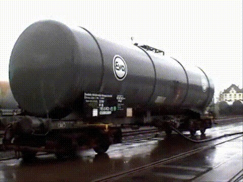
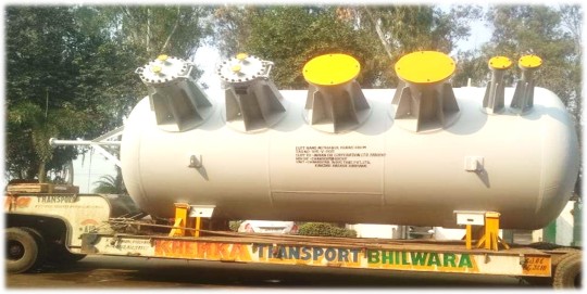
Two 1440PSI three-phase separators supplied by HC for the Tunisia project are about to be delivered.
Specifications:
Size: 42” x 10’
Design Pressure: 1440 psi
Design Temperature: -29 to 121°C
Service: Standard Service
Corrosion Allowance: 3 mm
Pressure Rating: 900#
Standards: ASME B31.3, ASME Sec VIII Div.1, ASME U Stamp
For more information on our three-phase separators and other oil and gas testing equipment, please visit our website or contact our sales team. [email protected]
1 note
·
View note
Text
Storage Vessel Manufacturers and Suppliers in India
Looking for Storage vessel manufacturers and suppliers? If yes, then look no further than Chanderpur Group. We are a reputable and leading storage vessel provider and deliver products across the world. These vessels have a thickness of up to 100mm and a weight of up to 100 mm. These are made of materials like carbon steel, alloy steel, and stainless steel. We are one of the best and most well-established Storage vessel manufacturer suppliers. We cater to the storage needs of different industries across the world. You can expect high-quality, robust, and reasonably priced storage vessels from us for your facility.

These vessels have a thickness of up to 100mm and a weight of up to 100 mm. Visit our website to get more information. Chanderpur Group is an established name as a Storage vessel manufacturer's supplier having a stronghold in many nations worldwide. Whatever needs you have related to storage, we can cater to your needs. Our storage vessels are made of superior quality materials, and they are designed well per your storage needs. Get in touch with us to get more information.
In search of Storage vessel manufacturers and suppliers who can provide you with robust and well-built storage vessels. If yes, count onChanderpur Group to get high-quality products. We comply with the ASME Sec VIII Div-1 and we have great expertise and experience in manufacturing pressure vessels that are made out of Carbon Steel, Stainless Steel, Duplex 2205, Explosion Bonded Plates, etc.
When in need of Storage Vessel Manufacturers Suppliers in India then make sure you count on Chanderpur Group, a reputable provider. We manufacture and deliver high-quality vessels that are capable of catering to your storage needs. Our storage vessels comply well with ASME Sec VIII Div-1 and deliver the expected results.
If you are on the lookout for Storage vessel manufacturers' suppliers in India, then you can end your search at Chanderpur Group. Our storage vessels are well-suited for all industries that have storage needs. We deliver robust quality vessels that are made of Carbon Steel, Stainless Steel, Duplex 2205, and Explosion Bonded Plates. Visit our website to get more information.
0 notes
Text
The vessel meaning

#THE VESSEL MEANING CODE#
Please subscribe to my monthly newsletter so you don't miss a thing. We will be updating and growing this site with more and more of industrial inspection related articles.
#THE VESSEL MEANING CODE#
What is API Code Definition from Pressure Vessel ? a vessel important in establishing and maintaining. a vessel that parallels another vessel, a nerve, or other structure. blood vessel any of the vessels conveying the blood an artery, arteriole, vein, venule, or capillary. Non pressure parts welded directly to a pressure retaining surface any channel for carrying a fluid, such as blood or lymph called also vas.The first sealing surface for proprietary connections or fittings.The face of the first flange for bolted, flanged connections For reasons of force majeure or distress or for rendering assistance to persons, ships or aircraft in danger or distress vessel, vessels will automatically be.The first threaded joint for screwed connections.The welding end of the first circumferential joint for welded connections.Also for gas fired double shell heat exchangers Many different kinds of vessels are used in commercial, artisanal. Inside diameter to be higher than 152 mm A fishing vessel is a boat or ship used to catch fish in the sea, or on a lake or river.The vessel with maximum allowable working pressure(MAWP) higher than 15 psi.These scopes are based ASME Code Sec VIII Div 1 The ASME Code is a construction code for pressure vessels and contains mandatory requirements, specific prohibitions and non-mandatory guidance for pressure vessel materials, design, fabrication, examination, inspection, testing, and certification.
0 notes
Text
Water naphtha separator
Water naphtha separator
The vapours of water and naphtha exiting the flash evaporator are condensed in a condenser and separated in the separator taking advantage of density difference and transferred to separate tanks.

The separated naphtha and waste water are transferred intermittently to storage tanks under overall and interface level control respectively.
The separator is designed as per ASME Sec VIII Div 1
Specially Designed Water – Naptha Separator Ensures Drastic Reduction of Oil Content in to Waste water and it also improves the COD&BOD in to the Waste Water.
Overall it Reduces the Effluent Treatment Plant Load in a Big Way.
www.thermopac.in
0 notes
Text
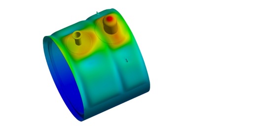
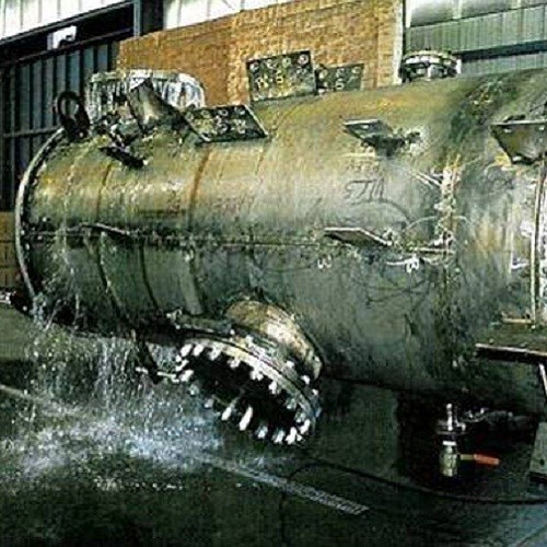
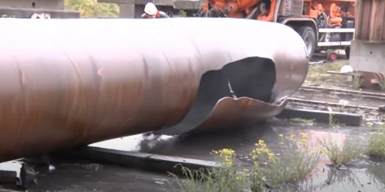
FEA EVALUATION OF MOUNDED BULLET TANKS – EEMUA 190

Mounded Bullet tanks are horizontal cylindrical tanks to store large quantities of Butane, Propane, Liquified petroleum gas (LPG) and other highly inflammable gases. Mound over the tanks eliminates the Boiling Liquid expanding vapour explosion (BLEVE) and also protect the tank from fire engulfment, radiation of fire and vandalism
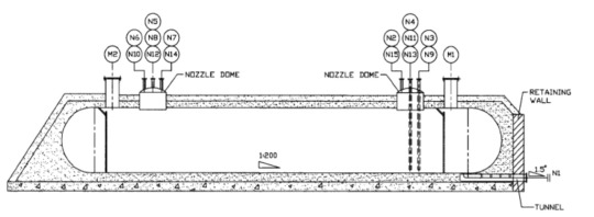
The Mounded Bullet tanks are designed as per ASME Sec VIII Div-1 and Div-2, BS 5500, PD 500 and EEMUA 190
Here in this article, we shall discuss on the analyses as per EEMUA 190. Through the design calculations the preliminary design of the vessel is made for the decided external and internal pressure. Then the following analyses are performed through FEA (New Product Design and Development using ALD) to validate the design and optimize the thickness of the shell and dish ends, number of stiffener rings and nozzle strength.
To know more on evaluation through ASME Sec VIII Div 1 and 2 – FEA evaluation of Pressure Vessels – ASME BPVC Section VIII Div-2
On step by step evaluation of the storage tanks, weak spots and optimization zones are infered.With our in-house team – 3D modelling and 3D to 2D conversion services team with experise in Heavy engineering and Pressure vessel analysis and storage tank development, we update the design and re-iterate for design study. On successful validation, we convert the 3D to 2D manufacturing and fabrication drawings as per clientele requirements and formats
Case -01 : Design Pressure Analysis
The internal and external pressure plays the vital role in design of all pressure vessels, storage tanks and allied products. The increase in internal pressure than the design pressure may lead to explosion and higher external pressure than designed may lead to other failures like implosions, cracks etc. In this analysis, the internal pressure head of the fluid, weight of the liquid and the tank and the external pressure due to moud are considered and evaluated.
Case -02 : Negative Pressure Analysis
In this analysis the mound bullet tank is evaluated to check the structural rigidity towards implosion. The storage tanks is tested for -0.5 bar pressure unless specified otherwises.
Case-03 : Hydrostatic Test Analysis
In this test the storage tanks are validated with 100% filled water and pressured to the prescribed level to quantify the strength of the shell and dish ends.Hydrotest allows to quantify the structural integrity of the storage vessel.
Case-04 : Burst Pressure Analysis
This analysis is performed to quantify the factor of safety of the storage vessel over the maximum allowable working pressure (MAWP). In general, it is expected to 4xMAWP but may vary due to specification and shall be iterated.
Case-05 : Imbalance Support Analysis
The soil under the bullet tanks are rammed and stiffened to withstand the load exerted by the tank but may not be even and may cause uneven support to the tank. The uneven support are simulated as per the following.

Case-06 : Seismic AnalysisAs storage tanks with highly inflammable fluids are of high importance and may cause catastrophic events in case of failure. So the storage tanks should not lose its structural integrity in case of natural calamities like floods, earthquakes and other such events based on location. Depending upon the location and seismic profile the tanks are validated.
Case-07 : Explosion of gas cloud
The high pressure gas explosion (BLEVE) above the mound may cause sudden increase in external pressure over the underlying storage tanks . It is calculated using the below correlations and validated for failure.
Gas Cloud Explosion load = (2R + ⅔ H) x L x 22.5m
Conclusion :
We at, Graphler Technology Solutions provide expert FEA services for Mounded Bullet Tanks. . We have a team of experts specialized in CAD Conversion Service, Engineering Animation Services and more
0 notes
Video
tumblr
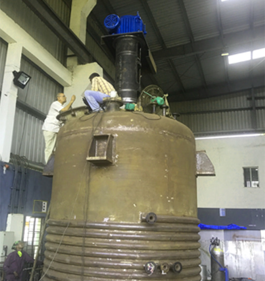
Stalwart designs Reactors in accordance with ASME Sec. VIII Div. I, AD Merkblatter and other international standards.
◆ Capacity (Design): 15KL
◆ Design Pressure (Kg/Cm²g): 1) Shell: F.V./3.0, 2) Limpet: 6.0, 3) Int. Coil: 6.0
◆ Hydro Test Pressure (Kg/Cm²g): 1) Shell: 3.9, 2) Limpet: 7.8, 3) Int. Coil: 7.8
◆ Design Temperature: 250℃reach us at,[email protected]
0 notes
Photo
Industrial Process Reactors - Chemical Reactors Suppliers Chennai
We manufacture high quality, robust process reactors as per ASME Sec VIII Div 1 & 2 standards. These process reactors are tailor made to suit the requirements of our clientele and are equipped with bottom / side entry agitators, thermic fluid reactors and water-cooled reactors and may range from 500 liters to 40 KL.
Stainless Steel Reactors.
Chemical Reactors.
Limpet Coil Reactors.
Thermic Fluid Reactors
Water cooled Reactors.
Jacketed Vessel.
0 notes
Link
We are looking for entry level skid engineer with minimum 2-year experience with below exposure. JOB Title: Skid Engineer Category: Chemical Injection / Process Packages Sector: Oil & Gas Experience Line: Process Vessels & Process Packages Minimum Experience Required: 2 Year minimum, Indian or UAE experience with same industry. Qualification Required: B Tech Mechanical / 3 Year Diploma in Mechanical Engineering Or any degree or diploma with 2-year minimum experience in Chemical Injection Skid / Process Package Skid Manufacturing. Must have good communication skill in English Language. Expected Salary: 3500 -4000 AED (Accommodation will be provided) Performing project requirements based on mechanical data sheet, PFD, P&ID, drawings, specification, ASME codes, NACE, HIC, PWHT/PMI, IGC, NDT, surface coating requirements. Understanding of materials, fittings, pipe, plates, forgings, internals etc. Required for estimation, technical evaluation of MR, raising technical clarifications and commercial bidding. Preparation of MTO, BOQ, Proposal, technical specifications Co-ordination with all interdisciplinary department including process, piping, instrument, planning, projects, electrical, procurement, design department for successful execution of projects with in given time frame. Active participation in technical meetings with vendors and clients. Act as the single point of contact with the client and to ensure that positive relations are maintained with client representatives within the contract obligations. Should be familiar with international codes & standards like ASME (Sec. VIII-DIV-1 & DIV-2, RTP-1, Sec. II, I etc.), API-6A, API-660, API-661, API-650, B31.3, B31.1, FEA, Aramco STD, Shell STD etc. As applied to static equipment in oil & gas industries. Meet deadlines to submission dates and organize workload Reviewing of PO and attend project kick-off meeting with the project team and assist project team for completing the projects in timely manner. Interested candidates with below experience please forward CV’ s with title “Skid Engineer – Oil & Gas” to “anilchathankeryATgmail.com”
0 notes
Text
مطلب جدید انتشار یافت در http://www.falateghareh.com/co2-2/
فروش خط تولید گاز کربنیک Co2
فروش خط تولید گاز کربنیک Co2
مشخصات فنی :
PRICE : (a)
۱ No. Equipment for CO2 Production Plant capacity ۷۵۶,۰۰۰ USD
۵۰۰ kg. CO2 Liquid/hr. complete with Generation,
Purification, Refrigeration, Liquification, Cylinder
filling and Lab. equipments for testing of quality and 1 No. Liquid CO2 Process tank of 20 Ton with PUF 200 mm insulation.
(b) 50 MT Liquid CO2 Horizontal Storage Tank as per ۹۳,۵۰۰ USD
ASME Sec. VIII, Div. 2 with Polyurethane 200 mm thick
insulation complete with Refrigeration system,
Instrumentations, piping, valves & Gauges,
Cylinder filling Unit, Safety Relief Valve,
Load cell based weighing system
Packing charges ۲۱,۲۴۰ USD
___________
Total FCA ICD PPG Delhi Price 870,740 USD
(Eight hundred seventy thousand seven hundred forty US Dollars only)
The above prices are FCA ICD / Patpar Ganj, New Delhi.
TERMS OF
PAYMENT a) 30% advance payment along with purchase order
b) 70% against irrevocable confirmed sight L/C from a first class international bank of
the buyer.
DELIVERY: The plant can be designed and supplied in 22 – ۲۴ weeks (approx) time from
#آموزش#خدمات بازرگانی#خدمات گمرکی#گارانتی با مشاوران داخلی و خارجی فلات قاره#نصب و راه اندازی#واردات ماشین آلات و تجهیزات صنایع نوشیدنی بهمراه مشاوره
0 notes
Text
High Pressure Vessels and Heat Exchangers – Chanderpur Group
CPG has come a long way since 1962, when we started manufacturing sugar machinery, through our collaboration with Christian Pfeiffer, Germany, in 2010. Today, we are a renowned engineering company offering multi-solutions and an international reputation with nearly 800 engineers working hard.
One of CPG's areas of expertise is manufacturing High Pressure Vessels and Heat Exchangers i.e stainless steel finned tubes, heat exchangers. ASME Sec- VIII Div-1 is the standard that we strictly adhere to, and we are experienced in manufacturing pressure vessels that are made of carbon steel, stainless steel, duplex 2205, explosion-bonded plates, etc.

Our areas of expertise include:
Oil & Gas
Chemical
Paper
Fertilizer
Our company can design, manufacture, and test customized heat transfer products for customers both domestically and internationally. Our expert engineers supervise the manufacturing of all these products, helping us to deliver an outstanding product line.
The following reasons account for Stainless steel finned tube heat exchangers wide acceptance in the marketplace:
Value for money
High Pressure
Moveable Support Brackets
Temperature Cross
Corrosion resistance
Longer life
Less maintenance
Precise dimension
Hardness
Optimum performance
U & R stamp has been granted to the pressure vessels division of this company.
Use of cold bending techniques, plates as thick as 120 mm and as wide as 3 m can be bent in this shop. The company also has other facilities, including a CNC lathe in which the x-axis is 10 meters long. This ensures that the final finish is of the highest quality and that the specifications are met to the exact degree.
Specification: -
Inside Dia 800 mm
Plate Thk. 16 mm
Design Pressure 10.5 Bar
MOC (Shell: SA 516 Gr. 70, Tubes: SA 213 TP 304)
A variety of engineering, procurement, and commissioning experiences give Chanderpur Group the flexibility to implement the success stories of one industry into another. Our team adheres to TQM and employs the latest testing methods to ensure quality. Our wide distribution network enables us to deliver our products to a variety of industries at the right time.
Consequently, our clients benefit from highly advanced electrical systems, automation systems, and energy-efficient products like stainless steel finned tube heat exchangers. We strive for excellent customer service and satisfaction as an organization. The accomplishments of our teams are a source of pride for us.
#pressure vessels and heat exchangers#high pressure vessels and heat exchangers#pressure vessels supplier india#pressure vessels manufacturers#pressure vessels manufacturers India
0 notes
Link
caesar ii pipe stress analysis
cast iron pipe fittings dimensions
piping arrangement
asme standards for pressure vessels
piping design course toronto
parts of valves
piping design course
asme sec 1
asme b31.3 latest edition pdf
fluid service
flange standard
asme 31.5
api 610 standard
allowable tensile stress
split wedge gate valve
concrete lined pipe
brazed joints
pressure design
asme process piping
boiler pressure vessel code
pipe abbreviations acronyms
asme standards for piping
design pressure vs operating pressure
asme sec ii part d
ansi b31.8
valve standards
pressure vessel asme code
asme section viii div 1
cement lined steel pipe
valve application
asme b31-3
asme boiler & pressure vessel code
asme 31
how to calculate allowable stress
maximum allowable stress for carbon steel
section i
valve code
how to join cast iron pipe
how to calculate design pressure
sustained loads
b31.3 asme
b31.3 code
piping specification codes
class 1500 valve pressure rating
structural skid design
caesar 2 training
power piping vs process piping
gasket design calculations
0 notes
Link
hand calculation pipe stress analysis how to calculate design pressure and design temperature pressure containing parts in ball valve valve bonnet b31 valve components boiler and pressure vessel code gate valve types asme 8 hoop stress formula for pipe section ii asme b 31.4 asme sections cement lined pipe asme section ii part d asme boiler code caesar ii training asme material class 800 pressure rating brazing and brazing qualifications piping design course asme section 2 part a maximum allowable working pressure for pipe di pipe jointing method cold working pressure stress intensification factor in piping ansi b31.8 asme vessel code asme b 31 lame equation gate valve wedge type ductile cast iron pipe piping layout design piping system design weld factor allowable stress table bell and spigot cast iron pipe fluid categories standard valve asme b31 series asme sec. viii sustained loads pipe properties power piping vs process piping piping standard asme b31 codes 1500 class valve pressure rating ansi 31.1 pipe load design pressure formula asme section iii pdf power piping code secondary load branch connection weld asme code section 1 design temperature vs operating temperature extruded header piping stress calculation b31.1 asme valve temperature rating class 1500 valve pressure rating asme b31.1 pipe support spacing bolted flange design spreadsheet steel allowable stress pipe allowable stress asme code b31.1 asme design pressure asme b31.3 welding fuel gas piping piping code and standard piping stress engineer pipe loads category d piping gas transmission and distribution piping systems branch connections piping what is pipe stress analysis category d service asme viii pressure vessel code flange leakage calculation design pressure of pipe external pressure calculation for pipe asme b31.3 questions and answers class 900 valve pressure rating design of piping systems b31 code asme b31 code for pressure piping asme b31.3 thickness calculation asme b 31.4 latest edition asme sec 5 article 2 asme b31.2 pdf section v formulas for stresses in bolted flanged connections flanged joint types of valves bolts and nuts asme 31.4 boiler code pipe support spacing asme b31 3 valves can be classified according to their use as skid design valve parts name asme vessels valves types pipe stress analysis software engineering services calgary overpressure protection flange assembly engineering firm calgary asme piping codes what is power piping asme b31 1 caesar stress analysis pipe layout asme bpv code valve part asme b31 8 asme power piping fluid service asme code for pressure vessel parts of valves part of valve caesar pipe stress branch connection wrc 107 piping design course toronto asme b31.3 latest edition pdf asme allowable stress table piping maintenance asme sec i concrete lined pipe valve body parts piping analysis api 610 standard pipe analysis asme piping design pressure vs operating pressure jacketed piping nozzle loads pipeline material properties asme section v article 2 allowable tensile stress pipe abbreviations acronyms asme 31 flange standard brazed joints asme section viii div 1 cast iron pipe fittings dimensions gate valve seat flange face types pressure design types of gate valves pipe stress engineer flange faces asme b31-3 asme boiler & pressure vessel code pipe wall thickness calculation split wedge gate valve section i sustained load b31.3 code asme sec ii part d b31.3 asme how to calculate design pressure asme standards for piping asme section v article 3 primary loads b31.1 vs b31.3 caesar 2 training asme b31.1 latest edition b31.11 pressure retaining parts basics of pipe stress analysis design asme performance test codes asme b31.5 pdf specified minimum yield strength b31.1 code asme b31. piping theory asme b31-1 sm23 asme boiler and pressure vessel code section ii part a pipe to pipe branch connection pipe thickness calculation piping specification codes asme material code valve class chart carbon steel allowable stress principles of piping layout rating valve astm b31.1 asme31.3 asme b3.1 allowable stress for carbon steel maximum allowable stress for carbon steel b31.3 category d b31.3 weld reinforcement welding factor spring hanger asme allowable stress pipe thickness calculation example what is piping design flange leakage ansi b31 piping design training
0 notes
Link
asme b31.3|asme b31.1|asme section 2|asme section ii|asme section iii|asme v|pipe stress analysis|asme section v|asme section viii|b31.3|asme b31|asme iii|asme b31.8|piping design|asme sec v|asme ii|asme 2|b31.1|valve class|valve class rating|piping stress analysis|asme b31.4|category d fluid|asme b31.9|nema sm23|asme viii|valve rating|category d fluid service|csa z662|asme 31.3|asme b31.3 pdf|asme b31.3 fluid categories|design pressure|asme b31.5|asme b31.3 allowable stress table|classification of valves|asme section 3|asme sec ii|asme sec 2|fluid service category|asme 31.1|design temperature|valve classification|pressure rating of valves|how to calculate design pressure for pipe|valve pressure class|valve parts|asme section 1|asme 3|valve pressure rating|nema sm 23|asme 31.8|piping codes|asme b31.3 wall thickness calculation|asme section i|ansi b31.1|asme section 5|asme boiler and pressure vessel code|b31.9|b31.3 fluid category|asme b 31.3|asme b31.3 process piping|b31.1 piping codeasme material properties b31.4 valve terminology piping stress analysis course asme sec iii flange stress calculations asme b31.3 category d valve class ratings valve rating class pipe stress b31.3 pdf stress analysis piping asme section ii part a stress intensification factor asme 31.9 category d fluid service asme b31.3 pipe design pressure wall thickness calculation asme b31.3 nozzle flexibility caesar ii weld strength reduction factor casting quality factor b31.3 normal fluid service piping power piping asme b31.2 asme 5 control valve types and applications branch connection in piping asme b31.11 asme sec 5 maximum stress intensity formula asme b31.3 impact test requirement nema sm23 nozzle loads valve classes asme pressure vessel code asme section 8 asme b 31.8 valve selection flange standards valves classification asme materials valve selection procedure seal weld threaded joint pipe thickness calculation as per asme b31.3 class valve weld joint factor nema sm 23 allowable loads b31.8 asme 1 control valve application category m fluid service asme sec ii part a asme bpvc section ii b31.2 asme b31.3 training valve pressure rating chart asme code section iii asme code section v classification of valve ansi b31.9 asme sec 2 part a secondary loads nema sm-23 asme b31.3 course normal fluid service asme category d fluid pipe stress analysis training slurry transportation piping systems weld joint strength reduction factor what is category d fluid service control valve applications what is class in valve asme b31 pressure piping code asme fluid category asme b31 3 category d vs normal allowable stress asme code parts of a valve pressure piping cast iron pipe joining methods ductile iron pipe joints pipe stress analysis services asme code section viii piping stress asme ii part a b31.5 maximum allowable stress piping code piping codes and standards pipeline stress analysis b31.1 welding code refractory lined pipe cast iron pipe joints pipe stress engineering class 800 valve pressure rating pipe loading ansi b31.4 stress analysis in piping nozzle load calculation pipe stress calculation class 300 valve pressure rating fluid code piping asme b31.1 power piping b31.3 process piping guided cantilever beam b31.3 piping code blind flange thickness calculation ansi/asme b31.1 over pressure protection class of valves fluid category boardman formula asme sec. v asme b31.9 pdf how to select valves in piping piping loads asme b31.1 power piping code cast iron pipe stress analysis flange joint valve types asme pressure vessel piping layout parts of valve ansi b31.3 pressure vessel code asme sec viii piping standards z662 cantilever method asme b 31.1 bolt selection piping abbreviations asme 31.5 ansi b 31.3 asmeb31.3 asme b 31.3 pdf asme ii part d asme boiler and pressure vessel code section viii asme b.31.3 category m fluid what is asme b31.3 asme section iii division 1 piping stress analysis training primary load asme material specification asme pressure vessel code section viii jacketed piping stress analysis steel pipe support spacing category d fluid service examples class 150 valve pressure rating codes and standards for piping valve class rating chart category m fluid service examples asme code section ii properties of pipe pipe stress analysis course pipeline design pressure guided cantilever what is design pressure of pipeline category d fluids introduction to pipe stress analysis guided cantilever method fluid category in asme b31.3 hand calculation pipe stress analysis how to calculate design pressure and design temperature pressure containing parts in ball valve valve bonnet b31 valve components boiler and pressure vessel code gate valve types asme 8 hoop stress formula for pipe section ii asme b 31.4 asme sections cement lined pipe asme section ii part d asme boiler code caesar ii training asme material class 800 pressure rating brazing and brazing qualifications piping design course asme section 2 part a maximum allowable working pressure for pipe di pipe jointing method cold working pressure stress intensification factor in piping ansi b31.8 asme vessel code asme b 31 lame equation gate valve wedge type ductile cast iron pipe piping layout design piping system design weld factor allowable stress table bell and spigot cast iron pipe fluid categories standard valve asme b31 series asme sec. viii sustained loads pipe properties power piping vs process piping piping standard asme b31 codes 1500 class valve pressure rating ansi 31.1 pipe load design pressure formula asme section iii pdf power piping code secondary load branch connection weld asme code section 1 design temperature vs operating temperature extruded header piping stress calculation b31.1 asme valve temperature rating class 1500 valve pressure rating asme b31.1 pipe support spacing bolted flange design spreadsheet steel allowable stress pipe allowable stress asme code b31.1 asme design pressure asme b31.3 welding fuel gas piping piping code and standard piping stress engineer pipe loads category d piping gas transmission and distribution piping systems branch connections piping what is pipe stress analysis category d service asme viii pressure vessel code flange leakage calculation design pressure of pipe external pressure calculation for pipe asme b31.3 questions and answers class 900 valve pressure rating design of piping systems b31 code asme b31 code for pressure piping asme b31.3 thickness calculation asme b 31.4 latest edition asme sec 5 article 2 asme b31.2 pdf section v formulas for stresses in bolted flanged connections flanged joint types of valves bolts and nuts asme 31.4 boiler code pipe support spacing asme b31 3 valves can be classified according to their use as skid design valve parts name asme vessels valves types pipe stress analysis software engineering services calgary overpressure protection flange assembly engineering firm calgary asme piping codes what is power piping asme b31 1 caesar stress analysis pipe layout asme bpv code valve part asme b31 8 asme power piping fluid service asme code for pressure vessel parts of valves part of valve caesar pipe stress branch connection wrc 107 piping design course toronto asme b31.3 latest edition pdf asme allowable stress table piping maintenance asme sec i concrete lined pipe valve body parts piping analysis api 610 standard pipe analysis asme piping design pressure vs operating pressure jacketed piping nozzle loads pipeline material properties asme section v article 2 allowable tensile stress pipe abbreviations acronyms asme 31 flange standard brazed joints asme section viii div 1 cast iron pipe fittings dimensions gate valve seat flange face types pressure design types of gate valves pipe stress engineer flange faces asme b31-3 asme boiler & pressure vessel code pipe wall thickness calculation split wedge gate valve section i sustained load b31.3 code asme sec ii part d b31.3 asme how to calculate design pressure asme standards for piping asme section v article 3 primary loads b31.1 vs b31.3 caesar 2 training asme b31.1 latest edition b31.11 pressure retaining parts basics of pipe stress analysis design asme performance test codes asme b31.5 pdf specified minimum yield strength b31.1 code asme b31. piping theory asme b31-1 sm23 asme boiler and pressure vessel code section ii part a pipe to pipe branch connection pipe thickness calculation piping specification codes asme material code valve class chart carbon steel allowable stress principles of piping layout rating valve astm b31.1 asme31.3 asme b3.1 allowable stress for carbon steel maximum allowable stress for carbon steel b31.3 category d b31.3 weld reinforcement welding factor spring hanger asme allowable stress pipe thickness calculation example what is piping design flange leakage ansi b31 piping design training
0 notes