#Compact Steam Flow Meter
Explore tagged Tumblr posts
Visit Tumblr Blog
Explore Tumblr blogs with no restrictions, modern design and the best experience.
Last Seen Tumblr Blogs


Fun Fact
There were a total of 171.5 billion posts on Tumblr in 2019.
Text
#Compact Steam Flow Meter#Compact Steam Flow Meter Supplier#Compact Steam Flow Meter Manufacturer#Compact Steam Flow Meter in Pune#Compact Steam Flow Meter in Mumbai
0 notes
Text
Cone and Conical Strainers: Essential Filtration Tools for Steam and Fluid Systems

In the world of fluid handling and steam systems, it is very important to ensure the smooth flow and purity of process media. Let’s just say that it is a non-negotiable. That’s where strainers come in — and more specifically, cone and conical strainers. These compact yet powerful devices play a critical role in protecting pipelines, valves, pumps, and other equipment from damage caused by foreign particles.
Whether you’re running a high-pressure steam line or handling corrosive liquids, choosing the right type of strainer — be it a cone strainer, T type strainer, or flanged strainer — can make all the difference in system reliability and performance. This blog takes a deep dive into cone and conical strainers, exploring their applications, advantages, and why they’re essential for both temporary and permanent filtration needs.
``What Are Cone and Conical Strainers?
Cone and conical strainers are shaped like a cone or a truncated cone, typically installed between flanges in pipelines. They are often used as temporary strainers during system startup to catch weld slag, rust, and other debris that may have accumulated during construction or maintenance.
Cone strainers are favored for their simplicity and efficient flow characteristics. When fluid passes through the cone, debris is trapped inside while clean fluid continues downstream. Because of their shape, cone strainers provide a larger open area compared to flat strainers, allowing higher flow rates and lower pressure drops.
Where Are They Used?
Cone and conical strainers are used across a wide range of industries:
Power plants: to protect turbines and boilers in high-temperature steam strainer applications
Chemical processing: to prevent clogging in precision metering and mixing equipment
Oil & Gas: for startup filtration in pipelines and separators
Pharmaceutical and food industries: to catch unwanted particles before they affect product quality
Water treatment: as part of pre-filtration systems to protect sensitive membranes and pumps
If your system deals with any fluid — hot or cold, corrosive or neutral — a stainless steel strainer in a conical form is often a smart first line of defense.
Key Advantages of Cone Strainers
Let’s break down why cone and conical strainers are preferred in demanding fluid systems:
1. Efficient Particle Capture
Their shape allows debris to collect without blocking the full flow path. This ensures continuous operation even with partial clogging, which is crucial in high-duty systems.
2. Low Pressure Drop
Thanks to the larger surface area compared to basket or flat strainers, cone strainers typically result in less pressure drop — ideal when maintaining pressure is vital.
3. Easy to Install and Remove
Cone strainers are generally placed between two flanges, making them easy to insert or remove during maintenance or startup checks.
4. Customizable Designs
They are available in various mesh sizes, materials, and configurations to suit different flow rates and particle sizes.
Choosing the Right Material: Why Stainless-Steel Strainers Lead the Pack

One of the most common choices for cone strainers is stainless steel, and for good reasons. Stainless steel strainers offer excellent resistance to corrosion, high temperature tolerance, and structural integrity even in extreme conditions. They’re particularly favored in steam systems and aggressive fluid applications where durability is critical.
From 304 to 316 stainless grades, you can select the right alloy based on the chemical compatibility and operating pressure/temperature of your system. Stainless steel also holds up better under frequent cleaning, another important factor in hygiene-sensitive industries like pharma and food processing.
Permanent vs Temporary: When to Use Cone Strainers
Cone strainers are primarily used as temporary strainers, especially in startup situations when it’s important to flush out residual debris. However, they’re also used in low-maintenance systems as permanent strainers, provided they are monitored and cleaned regularly.
If your application requires regular filtration over a long period, you might want to consider a T type strainer or a Y type strainer — both of which are designed for easier access and maintenance. Still, for short-term, high-flow protection, a cone strainer is often the most practical solution.
Flanged Cone Strainers: Sealing Made Simple
Some cone strainers come with flanged ends, which simplifies installation in flanged piping systems. A flanged strainer ensures better sealing, reducing the risk of leaks and making it easier to achieve proper torque without damaging the mesh.
Flanged cone strainers are especially useful in high-pressure systems or critical applications where precise alignment and robust sealing are required. They also minimize installation time, especially when compared to custom clamping or welding methods.
Choosing the Right Mesh and Size
Selecting the right mesh size is vital for optimal performance. The mesh must be fine enough to capture harmful debris but coarse enough not to choke flow. Typical mesh ranges are from 20 to 400 microns, but custom sizes are also available.
You should also consider:
Flow rate requirements
Particle size expected in the fluid
System pressure and temperature
Duration of use (temporary or permanent)
Consulting with filtration specialists or industrial strainer manufacturers can help you strike the right balance between protection and performance.
Whether you’re dealing with steam, chemicals, or process fluids, the role of a cone strainer should never be underestimated. It’s a simple, cost-effective solution that prevents significant damage, unscheduled downtimes, and performance issues in your pipeline.
Incorporating the right cone strainer, T type strainer, or flanged strainer into your system design isn’t just good practice, it’s essential engineering. And when durability is critical, stainless-steel strainers remain the gold standard for long-term efficiency and safety.
If you’re setting up a new fluid system or retrofitting an existing one, talk to experienced filtration specialists who can guide you to the right solution for your specific needs. Because in the process of filtration, precision matters — and a small strainer can save you from big problems down the line.
The location of installation of these Conical Strainers are in Brunei.
0 notes
Text
What Are DBB Valves? A Manufacturer’s Guide to Function, Design, and Worldwide Applications

In industries where safety, reliability, and system integrity are absolutely crucial, Double Block and Bleed (DBB) valves have become essential. These valves are widely used in critical sectors like oil and gas, petrochemicals, power generation, and marine applications, providing enhanced isolation capabilities that protect both equipment and personnel.
So, what are DBB valves all about? How do they function? And why do industries around the world trust them?
In this blog, we’ll dive into the function, design, and global applications of DBB valves, sharing insights from seasoned valve manufacturers like ICCL.
🔧 What Is a DBB Valve?
A Double Block and Bleed (DBB) valve is a specialized valve assembly designed to ensure positive isolation from both sides of a pressure system. It combines two block (or isolation) valves with a bleed valve into one compact unit. This clever design allows operators to:
- Block flow from both the upstream and downstream sides
- Bleed or vent the space between the two blocks to atmospheric pressure
This arrangement guarantees that any pressure trapped between the two isolation points can be safely released, preventing cross-contamination and allowing for maintenance or instrumentation work to be done safely.
✅ DBB Valve vs. Traditional Valve Assembly
In traditional setups, two separate valves with a bleed port in between are installed in sequence. This not only takes up more space but also creates multiple potential leak paths. DBB valves combine all three functions (Block, Block, and Bleed) into a single, compact valve body, which reduces:
- Installation time
- Space and weight
- Potential leak points
- Maintenance complexity
That’s why DBB valves have become the preferred global standard in high-pressure and hazardous applications.
🛠️ How Do DBB Valves Work?
The principle behind their operation is simple yet highly effective:
Block 1 (Primary Isolation): The first valve halts the upstream process fluid.
Block 2 (Secondary Isolation): This second valve is designed to stop any backflow from the downstream side.
Bleed Valve (Vent): Nestled between the two blocks, the small bleed valve lets you safely vent or drain any trapped media.
When both block valves are shut and the bleed valve is opened, any leftover pressure between the blocks is released. This creates a verifiable zero-pressure zone, which is essential for safe maintenance and calibration.
🌍 Global Applications of DBB Valves
DBB valves are utilized in a variety of industries around the globe, thanks to their reliable isolation features:
Oil & Gas: Used for isolating pipelines, metering stations, offshore platforms, and manifolds.
Petrochemical & Chemical: Essential for isolating hazardous chemicals and ensuring safe venting during shutdowns.
Power Plants: Key components in steam and condensate systems, as well as boiler connections.
Refineries: Critical for managing high-pressure hydrocarbon lines and product transfer systems.
Marine & Shipbuilding: Important for controlling fuel and ballast systems.
Their capacity to withstand high pressures (up to 10,000 psi or more) and extreme temperatures makes them perfect for vital global infrastructure.
🧠 Key Features of a Great DBB Valve (From a Manufacturer's Perspective)
Leading manufacturers like ICCL highlight these key features in top-notch DBB valves:
1. Compact and Integrated Design
By merging multiple valve functions into a single unit, DBB valves minimize the installation footprint—especially advantageous in offshore and modular setups.
2. Precision Machining and Tolerances
The components of the valve—particularly the seats and spindle mechanisms—need to be crafted to tight tolerances to guarantee bubble-tight shutoff and safe venting.
3. Material Compatibility
Depending on the media and pressure conditions, the materials used can include:
Stainless Steel (SS316, SS316L)
Duplex/Super Duplex
Inconel,Monel, or Hastelloy for corrosive environments
All materials must meet international standards like NACE MR0175 and PED.
4. Pressure Testing and Certification
Every valve needs to undergo thorough hydrostatic and pneumatic testing, and it should come with complete Material Test Certificates (MTCs) along with international certifications like API, CE, and ISO.
5. Customization Options
Leading manufacturers provide a variety of configurations, including:
- Flanged, threaded, or welded end connections
- Soft or metal seats
- Integral vent plugs or test ports
- Fire-safe or anti-blowout designs
🌐 Why ICCL DBB Valves Are Trusted Worldwide
ICCL (International Control Components Ltd.) has built a solid reputation in the field of instrumentation and industrial valve manufacturing, serving clients from Asia to the Middle East, Europe, and the Americas. ICCL's DBB valves are:
- Designed for critical applications that handle hazardous and corrosive fluids
- Produced under ISO 9001-certified systems
- Rigorously tested and certified to comply with global safety standards
- Tailored to meet client specifications with quick turnaround times and worldwide support
You can find their valves in refineries in the UAE, FPSOs in Brazil, chemical plants in Germany, and power grids in India—demonstrating the brand’s reliability across different regions.
🔒 The Safety Factor ��
One of the main reasons DBB valves are favored around the globe is their significant contribution to operational safety. Whether it’s isolating high-pressure lines or allowing instrumentation technicians to work without the fear of backflow, DBB valves provide a level of security that traditional valve setups simply can’t match.
This makes them essential in safety-critical industries—where system failures could lead to environmental disasters or even loss of life.
DBB valves are more than just another component; they are vital safety and performance assets in today’s industrial systems. From ensuring safe maintenance to delivering zero-leak isolation, their role is crucial worldwide.
As industries become increasingly complex and safety regulations become stricter, selecting the right DBB valve—one that meets the highest manufacturing standards—is more important than ever.
0 notes
Text
Everything You Need to Know About Small Rubber Bellows and Expansion Joints
Tight spaces demand smart parts like small rubber bellows for protection. They fill in holes or protect tools against dust, heat, or vibration. They will be in pumps, cars, HVAC systems, and test labs. They flex easily, retain their shapes and seal fluid/air leakage. They accept wear without cracking or tearing.
Each unit should be compatible to eliminate breakdown or leak paths. They aid in smooth movements of joints, even in gravel or crowded areas. These bellows exclude dust and allow free movement of the part. Seal and shape control are a big factor in use.
It is possible to ask your rubber bellow manufacturer whether they cut to shape or mold. Some are circular, and some are cone or oval-shaped to fit joint angles. They are great with heavy tools as well as delicate laboratory equipment. Having the reliability below implies fewer failures in parts and fewer downtimes in the system.
What Are Small Rubber Bellows?
They are small, flexible covers used in narrow joint systems. These bellows help block dirt, moisture, and unwanted air leaks. Most units are made of durable rubber or synthetic elastomers. They fit well in valves, meters, vents, and handheld tools. A good rubber bellow manufacturer tests for durability and sealing ability. They are perfect for spots that face low movement or strain.
Unlike metal parts, rubber bellows won’t rust or wear easily. Their main role is to protect and extend the device’s life. Companies design each unit to flex slightly without cracking or tearing. They prevent minor gaps from turning into major leak issues quickly. There are devices like vacuum pumps that often rely on them for smooth operation.
You’ll see them around cable joints, actuators, or small pipe ends. Some are molded precisely for odd shapes and custom spaces. Manufacturers use different rubbers based on temperature or load needs. Bellows work well where frequent bending or twisting is expected. They are found in medical tools, auto parts, and lab systems.
The size and shape vary based on joint angle and motion. Flexibility matters most when choosing bellows for any moving zone. Pressure resistance and sealing range also guide the right material choice. A trusted small rubber bellows provider will offer test reports and specs. The low-load areas benefit the most from compact bellow designs today.
The quality makes all the difference in performance and part lifespan. The companies keep refining shapes to match new machinery and tight spaces.
Why Use Bellows Expansion Joint?
They absorb pipe shifts caused by heat, flow, or system pressure. This helps protect bolts, seals, and nearby pipe ends from strain. These joints keep systems stable during fast temperature or pressure changes. A well-made bellows expansion joint reduces noise and shaking during operations. They’re common in ducts carrying steam, gas, air, or exhaust gases.
Many companies prefer them for tough jobs that need both strength and flexibility. The shape allows a slight stretch without breaking the pipe path. The unit is tested to handle a wide range of flow rates. Expansion joints lower the risk of breaks in HVAC and boiler lines. They also prevent cracks where pipes meet rigid supports or corners.
Many engineers pick them when piping runs long distances or spans floors. They help move loads safely without stiff pipe stress or misalignment. Their use keeps maintenance costs low and system safety high long term. A tested bellows expansion joint performs well even in high-heat conditions. They resist wear caused by heat cycles, sharp bends, or fast flow.
The material choice depends on the fluid type, system size, and working heat range. They give more life to joints while keeping the flow steady.
Pick the Right Molded Rubber Bellows
These bellows are formed to exact shapes for better part sealing. A tight fit means no leaks, even in high-stress zones. You can pick U, S, cone, or rounded bellow shapes easily. Each shape suits different joint angles, strokes, and system needs. A trusted rubber bellow supplier will guide size and shape matching.
You must check the inner and outer diameters before choosing. The stroke length and wall thickness also matter in tight fits. The molded types flex smoothly and last longer in wear-heavy areas. They suit pumps, valves, and moving seals exposed to rough conditions. The companies test them under load to check crack or tear risks.
You can pick material based on oil contact, heat level, and movement style. Nitrile works for oil; silicone fits high-heat or medical spaces. Neoprene is strong for general use and has light chemical resistance. A custom bellow prevents bellow failure during pressure spikes or sharp turns. Every unit of molded rubber bellows must match function, not just size.
The fit should allow full motion without stretch or collapse risks. The reliable companies provide guides or drawings for better part matching. The right choice saves repair costs and improves the full system life.
How to Choose a Rubber Bellow Manufacturer?
You check if the company follows ISO and full QC processes. They should use digital tools to test leaks, fit, and strength. You must ask if they mold in-house or send parts out. The in-house work gives better control and faster changes if needed. A trusted company must show test pieces or sample part runs.
Strong mold skills are key for tight parts like small rubber bellows. You can ask about low-volume orders, not just big bulk batches. This shows they handle both custom and large-scale client needs. A good firm explains its full flow from design to final test. It helps if they share past work or client industries served.
Materials used should match heat, oil, or stretch needs clearly. Some firms offer only basic types, so confirm before the final deal. They must be able to make round, oval, or cone shapes. You’ll want smooth edges, clean lines, and flexible yet tough rubber. If you need a bellows expansion joint, ask about the pressure range. You can look for clarity in quotes and no hidden extra charges later.
Conclusion
The firms test for crack points, heat limits, and stretch life too. A trusted rubber bellow supplier gives full data, not just product names. They help match the right bellow to your load and job. Bellows may look simple, but good ones make big systems last.
Contact us more to know about the products. Get in touch to know the quote!
0 notes
Text
Why Is a Y Strainer Crucial in Modern Fluid Systems?
A Y Strainer is an essential component for protecting valves, pumps, and meters in pipelines by filtering out debris and solid particles. Designed in a compact Y-shape, it offers easy maintenance and efficient filtration, making it ideal for steam, gas, or liquid systems. Whether used in industrial, commercial, or residential settings, Y strainers reduce wear and tear, ensuring longer equipment life and smoother operations. With increasing demand for low-maintenance and reliable flow control, Y strainers are more relevant than ever. Explore our premium-grade Y Strainers today—visit our official website to learn more and request a quote!

0 notes
Text
Leading Dosing Pump Manufacturer in India | Supplier of Industrial Dosing Pumps
Find premium dosing pumps from the top manufacturer in India. For industrial, chemical, and water treatment applications, Unique Dosing Pumps provides sophisticated, long-lasting, and effective dosing pump systems.
Dependable Dosing Pumps for Industrial Accuracy - Produced by Professionals
Accurate fluid control is essential in today's industrial setting. Whether used in food-grade applications, water treatment, or chemical processing, dosing pumps are essential for precise and regulated liquid dispensing. As a leading dosing pump manufacturer in India, Unique Dosing Pumps provides cutting-edge solutions that are suited to the demands of the particular industry.
A Dosing Pump: What Is It?
A dosing pump is a kind of positive displacement pump made especially to add a precise volume of liquid to a steam, gas or water flow. pumps, in contrast to conventional pumping systems, are designed for micro-level accuracy and are frequently employed in applications where precise fluid or chemical delivery is crucial.
Dosing technology guarantees uniformity, effectiveness, and safety in everything from controlling pH levels in water treatment plants to distributing additives in the manufacturing of food and beverages.
Our Selection of Dosing Pumps
A wide range of dosing equipment, constructed with high-quality materials and state-of-the-art engineering, is available from Unique Dosing Pumps. Every model is designed to withstand harsh environments and provide dependable metering.
Devoted to Innovation and Quality
Our goal is to provide dosing systems that guarantee sustainability, safety, and accuracy. Every unit produced by Unique Dosing Pumps is of unparalleled quality thanks to rigorous internal testing and adherence to international manufacturing standards.
By creating smarter, more energy-efficient pumps that lower operating costs and have a smaller environmental impact, we are constantly innovating to meet the changing needs of industries.
Our Selection of Dosing Pumps
A wide range of dosing equipment, constructed with high-quality materials and state-of-the-art engineering, is available from Unique Dosing Pump. Every model is designed to withstand harsh environments and provide dependable metering.
1. Solenoid Operated Dosing Pumps
Compact, lightweight, and ideal for low-pressure dosing tasks
Energy-efficient and electronically controlled
Common in cooling towers, RO plants, and chlorination units
2. Motor-Driven Dosing Pumps
Designed for higher flow rates and pressures
Rugged construction with corrosion-resistant materials
Suitable for ETP, STP, and chemical dosing
3. Mechanical Diaphragm Dosing Pumps
Economical solution for medium-pressure dosing
Simplified design with minimal maintenance needs
Widely used in agriculture, fertigation, and basic water treatment
4. Hydraulic Diaphragm Dosing Pumps
Engineered for hazardous or corrosive fluids
Leak-free operation enhances safety in chemical handling
Best for industries with stringent safety protocols
Customer Contentment and Industry Presence
Unique Dosing Pumps is known for its dependable service, prompt delivery, and reasonably priced dosing solutions. The company serves customers throughout India and exports to foreign markets. Our products have gained the confidence of prestigious customers, ranging from private sector manufacturers to municipal water projects.
Join Forces with Precision Dosing Experts
The foundation of any system that requires precision and control is a dependable dosing pump. At Unique Dosing Pump, we use our technological expertise and decades of experience to deliver cutting-edge dosing pumps that go above and beyond industry standards. We have the answer whether you're looking for a sturdy system for handling chemicals on a large scale or a small pump for a specific application.
View our product line or get in touch with our staff for a personalised quote right now. To learn more, go to Unique Dosing Pumps.
Visit: https://www.uniquedosingpumps.com/dosing-pump-manufacturers.php
Contact: +91 9822420535
0 notes
Text
Spring Loaded Check & Non-Return Valves – Selection Guide & Best Suppliers in Delhi
Spring-loaded check and non-return valves play a crucial role in fluid control systems, industrial piping, water supply, and fuel distribution networks. These valves use a spring mechanism to allow fluid flow in one direction while preventing backflow, ensuring system efficiency and protection.
As a leading manufacturer and supplier of spring-loaded check and non-return valves in Delhi, Udhhyog provides high-quality, durable, and precision-engineered solutions designed for industrial, commercial, and municipal applications.
This guide covers types of spring-loaded check and non-return valves, their applications, pricing details, and selection criteria.
What are Spring Loaded Check & Non-Return Valves?
A spring-loaded check valve is a mechanical device that allows fluid to flow in one direction and automatically closes when the flow stops. The spring mechanism ensures a quick closure, preventing reverse flow.
A non-return valve (NRV) is designed to prevent backflow in pipelines, ensuring that fluids or gases move in only one direction.
Key Benefits of Spring Loaded Check & Non-Return Valves:
✔ Prevents backflow and contamination.
✔ Ensures smooth operation in pressurized systems. ✔ Reduces maintenance and extends system lifespan. ✔ Available in stainless steel, brass, and corrosion-resistant materials. ✔ Used in water supply, fuel pipelines, and industrial processes.
Spring Loaded Check Valve Diagram & Symbol
A spring-loaded check valve diagram visually represents how the spring mechanism allows one-way flow and prevents reverse flow, while the symbol is commonly used in engineering schematics.
Types of Spring Loaded Check & Non-Return Valves
At Udhhyog, we manufacture and supply various spring-loaded check and non-return valves for different industrial needs.
1. Spring Loaded Swing Check Valve
Uses a swinging disc and spring mechanism to control flow.
Used in municipal water supply, fuel systems, and industrial pipelines.
2. Spring Loaded Lift Check Valve
Features a piston-like mechanism to prevent backflow.
Ideal for steam, gas, and chemical processing applications.
3. Inline Spring Loaded Check Valve
A compact, inline design for space-efficient installations.
Used in compressed air, refrigeration, and fuel transfer systems.
4. Spring Loaded Dual Plate Check Valve
Two plates open with fluid flow and close with spring force.
Common in high-pressure applications and large industrial pipelines.
5. Spring Loaded Non-Return Valve (NRV)
Prevents backflow of liquids or gases in pressurized systems.
Used in HVAC, chemical processing, and fire protection systems.
Where are Spring Loaded Check & Non-Return Valves Used?
1. Water Supply & Plumbing Systems
Ensures clean water flow by preventing backflow contamination.
Protects pumps and water meters from reverse flow damage.
2. Oil & Gas Industry
Maintains one-way flow in fuel and gas pipelines.
Prevents leakage and pressure drops in petroleum refineries.
3. HVAC & Fire Protection Systems
Used in fire sprinkler networks to keep water flow consistent.
Prevents airlocks and pressure surges in heating and cooling systems.
4. Industrial Processing & Chemical Plants
Regulates fluid pressure and prevents contamination in pipelines.
Ensures safe flow control in hazardous chemical processing units.
5. Hydraulic & Pneumatic Systems
Protects hydraulic pumps and compressed air systems.
Maintains proper pressure balance in industrial machinery.
Spring Loaded Check & Non-Return Valve Price List
Latest Prices for Different Spring Loaded Valves
Valve TypeSizePrice Range (INR)Spring Loaded Swing Check Valve1/2 to 4 Inch₹1,500 - ₹7,500Spring Loaded Lift Check Valve1 to 6 Inch₹2,500 - ₹12,000Inline Spring Loaded Check Valve1 to 6 Inch₹3,500 - ₹15,000Spring Loaded Dual Plate Check Valve1 to 6 Inch₹4,500 - ₹20,000Spring Loaded Non-Return Valve1/2 to 6 Inch₹1,800 - ₹10,500
📌 Note: Prices may vary based on size, material, and bulk order discounts. Contact Udhhyog for the latest pricing.
How to Select the Right Spring Loaded Check & Non-Return Valve?
1. Application Type
For water & plumbing systems – Use a spring-loaded swing check valve.
For steam and gas pipelines – Choose a spring-loaded lift check valve.
For high-pressure applications – Select a spring-loaded dual plate check valve.
2. Size & Pressure Rating
1/2 to 2 inches for low-pressure applications.
3 inches & above for high-pressure industrial use.
3. Material Selection
Brass check valves for corrosion resistance.
Stainless steel check valves for high-pressure environments.
Cast iron non-return valves for heavy-duty industrial use.
4. Connection Type
Threaded check valves for quick installation in pipelines.
Flanged check valves for large-scale industrial applications.
5. Manufacturer & Supplier Reliability
Buy from trusted manufacturers like Udhhyog to ensure high-quality and durable spring-loaded check and non-return valves.
Why Choose Udhhyog – Best Spring Loaded Valve Supplier in Delhi?
At Udhhyog, we manufacture and supply high-performance spring-loaded check and non-return valves for various industries.
✅ Premium-Quality Materials
We manufacture spring-loaded valves using brass, stainless steel, and high-grade alloys for durability.
✅ Competitive Pricing
Our prices are affordable, making us the preferred supplier for industries and commercial buyers.
✅ Wide Range of Valves
We supply spring-loaded check valves, non-return valves, inline check valves, and dual plate check valves.
✅ Fast & Reliable Delivery
We ensure on-time deliveries across Delhi, Haryana, Uttar Pradesh, and Jammu & Kashmir.
Contact Udhhyog for the Best Spring Loaded Check & Non-Return Valves
📞 Call Us Today or Visit Udhhyog to explore our range of spring-loaded check and non-return valves.
✨ Choose Udhhyog – Your Trusted Check & NRV Supplier!
#SpringLoadedValve#CheckValve#NonReturnValve#IndustrialValves#PlumbingSolutions#ValveSupplier#DelhiManufacturer#Udhhyog#PressureControl#HVACSystems
1 note
·
View note
Text
Spring Loaded Check & Non-Return Valves – Selection Guide & Best Suppliers in Delhi
Spring-loaded check and non-return valves play a crucial role in fluid control systems, industrial piping, water supply, and fuel distribution networks. These valves use a spring mechanism to allow fluid flow in one direction while preventing backflow, ensuring system efficiency and protection.
As a leading manufacturer and supplier of spring-loaded check and non-return valves in Delhi, Udhhyog provides high-quality, durable, and precision-engineered solutions designed for industrial, commercial, and municipal applications.
This guide covers types of spring-loaded check and non-return valves, their applications, pricing details, and selection criteria.
What are Spring Loaded Check & Non-Return Valves?
A spring-loaded check valve is a mechanical device that allows fluid to flow in one direction and automatically closes when the flow stops. The spring mechanism ensures a quick closure, preventing reverse flow.
A non-return valve (NRV) is designed to prevent backflow in pipelines, ensuring that fluids or gases move in only one direction.
Key Benefits of Spring Loaded Check & Non-Return Valves:
✔ Prevents backflow and contamination.
✔ Ensures smooth operation in pressurized systems. ✔ Reduces maintenance and extends system lifespan. ✔ Available in stainless steel, brass, and corrosion-resistant materials. ✔ Used in water supply, fuel pipelines, and industrial processes.
Spring Loaded Check Valve Diagram & Symbol
A spring-loaded check valve diagram visually represents how the spring mechanism allows one-way flow and prevents reverse flow, while the symbol is commonly used in engineering schematics.
Types of Spring Loaded Check & Non-Return Valves
At Udhhyog, we manufacture and supply various spring-loaded check and non-return valves for different industrial needs.
1. Spring Loaded Swing Check Valve
Uses a swinging disc and spring mechanism to control flow.
Used in municipal water supply, fuel systems, and industrial pipelines.
2. Spring Loaded Lift Check Valve
Features a piston-like mechanism to prevent backflow.
Ideal for steam, gas, and chemical processing applications.
3. Inline Spring Loaded Check Valve
A compact, inline design for space-efficient installations.
Used in compressed air, refrigeration, and fuel transfer systems.
4. Spring Loaded Dual Plate Check Valve
Two plates open with fluid flow and close with spring force.
Common in high-pressure applications and large industrial pipelines.
5. Spring Loaded Non-Return Valve (NRV)
Prevents backflow of liquids or gases in pressurized systems.
Used in HVAC, chemical processing, and fire protection systems.
Where are Spring Loaded Check & Non-Return Valves Used?
1. Water Supply & Plumbing Systems
Ensures clean water flow by preventing backflow contamination.
Protects pumps and water meters from reverse flow damage.
2. Oil & Gas Industry
Maintains one-way flow in fuel and gas pipelines.
Prevents leakage and pressure drops in petroleum refineries.
3. HVAC & Fire Protection Systems
Used in fire sprinkler networks to keep water flow consistent.
Prevents airlocks and pressure surges in heating and cooling systems.
4. Industrial Processing & Chemical Plants
Regulates fluid pressure and prevents contamination in pipelines.
Ensures safe flow control in hazardous chemical processing units.
5. Hydraulic & Pneumatic Systems
Protects hydraulic pumps and compressed air systems.
Maintains proper pressure balance in industrial machinery.
Spring Loaded Check & Non-Return Valve Price List
Latest Prices for Different Spring Loaded Valves
Valve TypeSizePrice Range (INR)Spring Loaded Swing Check Valve1/2 to 4 Inch₹1,500 - ₹7,500Spring Loaded Lift Check Valve1 to 6 Inch₹2,500 - ₹12,000Inline Spring Loaded Check Valve1 to 6 Inch₹3,500 - ₹15,000Spring Loaded Dual Plate Check Valve1 to 6 Inch₹4,500 - ₹20,000Spring Loaded Non-Return Valve1/2 to 6 Inch₹1,800 - ₹10,500
📌 Note: Prices may vary based on size, material, and bulk order discounts. Contact Udhhyog for the latest pricing.
How to Select the Right Spring Loaded Check & Non-Return Valve?
1. Application Type
For water & plumbing systems – Use a spring-loaded swing check valve.
For steam and gas pipelines – Choose a spring-loaded lift check valve.
For high-pressure applications – Select a spring-loaded dual plate check valve.
2. Size & Pressure Rating
1/2 to 2 inches for low-pressure applications.
3 inches & above for high-pressure industrial use.
3. Material Selection
Brass check valves for corrosion resistance.
Stainless steel check valves for high-pressure environments.
Cast iron non-return valves for heavy-duty industrial use.
4. Connection Type
Threaded check valves for quick installation in pipelines.
Flanged check valves for large-scale industrial applications.
5. Manufacturer & Supplier Reliability
Buy from trusted manufacturers like Udhhyog to ensure high-quality and durable spring-loaded check and non-return valves.
Why Choose Udhhyog – Best Spring Loaded Valve Supplier in Delhi?
At Udhhyog, we manufacture and supply high-performance spring-loaded check and non-return valves for various industries.
✅ Premium-Quality Materials
We manufacture spring-loaded valves using brass, stainless steel, and high-grade alloys for durability.
✅ Competitive Pricing
Our prices are affordable, making us the preferred supplier for industries and commercial buyers.
✅ Wide Range of Valves
We supply spring-loaded check valves, non-return valves, inline check valves, and dual plate check valves.
✅ Fast & Reliable Delivery
We ensure on-time deliveries across Delhi, Haryana, Uttar Pradesh, and Jammu & Kashmir.
Contact Udhhyog for the Best Spring Loaded Check & Non-Return Valves
📞 Call Us Today or Visit Udhhyog to explore our range of spring-loaded check and non-return valves.
✨ Choose Udhhyog – Your Trusted Check & NRV Supplier!
#SpringLoadedValve#CheckValve#NonReturnValve#IndustrialValves#PlumbingSolutions#ValveSupplier#DelhiManufacturer#Udhhyog#PressureControl#HVACSystems
0 notes
Text
Different Types of Flange Connections
Flange connections are essential for joining pipes, valves, and other equipment in industrial applications. They provide strength, flexibility, and ease of maintenance.
Types of Flange Connections
1. Weld Neck Flange
Long tapered hub for high-pressure applications
Reduces stress concentration at the base of the flange
Used in oil & gas, power plants, and petrochemical industries
2. Slip-On Flange
Slides over the pipe and welded from inside and outside
Easy to install and cost-effective
Suitable for low-pressure and low-temperature applications
3. Socket Weld Flange
Recessed socket for pipe insertion and fillet welding
Provides smooth bore and high fatigue resistance
Used in chemical, power, and hydraulic systems
4. Blind Flange
Solid flange without a bore to close pipe ends
Facilitates inspection and maintenance
Commonly used in pressure vessel and pipeline systems
5. Lap Joint Flange
Works with stub-end fittings for easy disassembly
Allows rotation for proper bolt alignment
Ideal for systems requiring frequent dismantling
6. Threaded Flange
Screwed onto pipes without welding
Best for low-pressure and non-hazardous applications
Commonly used in plumbing and small pipe connections
7. Orifice Flange
Designed for measuring flow rates in pipelines
Includes pressure taps for accurate readings
Used in metering and monitoring applications
8. Long Weld Neck Flange
Extended neck for added reinforcement
Used in high-pressure, high-temperature environments
Ideal for boiler and heat exchanger applications
9. Expander Flange
Increases pipe diameter at the connection point
Alternative to reducers for compact installation
Used in pipeline systems requiring diameter transition
10. Reducing Flange
Connects pipes of different diameters
Minimizes turbulence and pressure drop
Common in HVAC, water treatment, and chemical plants
Applications of Flange Connections
Oil & Gas – Used in pipelines, offshore rigs, and refineries
Water Treatment – Essential in desalination and filtration systems
Power Plants – Helps in steam, gas, and cooling systems
Chemical Industry – Ensures leak-proof and corrosion-resistant connections
HVAC Systems – Facilitates heating and cooling pipelines
FAQ Section
What is the most common type of flange connection?
Weld neck and slip-on flanges are the most widely used due to their strength and ease of installation.
Which flange is best for high-pressure applications?
Weld neck and long weld neck flanges are ideal for high-pressure environments.
How do I choose the right flange connection?
Consider factors like pressure, temperature, material compatibility, and maintenance requirements.
#FlangeConnections#IndustrialPiping#PipelineEngineering#HVAC#OilAndGas#ChemicalProcessing#PowerPlants#WaterTreatment
1 note
·
View note
Text
Comprehensive Guide to SS Needle Valve Manufacturer in India
Pedlcok is a leading Needle Valves and SS Needle Valves Manufacturer is designed for leak free closure, regulation and management of fluids in process systems. Needle Valve are precarious for instrumentation, fluid and process control system. With a widespread variety of port sizes, end connections, style, temperature and pressure tolerance. We are perceived as the decades of expertised Needle Valves and SS Needle Valves Manufacturer in Ahmedabad, Vadodara, Mumbai, Delhi, Chennai, Bangalore, Ghaziabad, Rajasthan, and Gujarat India. These needle valves or Hydraulic 3way ball valve are designed & formulated by using the first rate quality material and updated methods for its unique features, ideally finished structure and excellent functioning. Moreover, our hydraulic needle valve is largely utilized in different mechanization businesses so as to make variety of machines with the better conditions.

Understanding the Functionality of SS Needle Valves
SS needle valves are designed to provide precise control over the flow of fluids. The valve consists of a slender, tapered pin, known as the needle, which fits into a corresponding seat within the valve body. By rotating the valve stem, the needle moves closer to or farther away from the seat, thereby regulating the flow of fluid.
Key Features of SS Needle Valves
Compact design
Available in variety of material
Low operating Torques
Dust Cap provided
Variety of end connections includes Male / Female NPT, BSPT, BSPP
Every valve is factory tested
High Pressure Rating Available till 15000 psi
Needle Valves and SS Needle Valves are designed for Pressure up to 20,000 psi All valves are 100% factory tested with Dust and thread caps are provided as standard. Spindle is thread rolled and burnished for smooth operation and long life.
Applications of SS Needle Valves
SS needle valves are versatile components used across various industries. Below are some of the key applications where these valves play a critical role:
Oil and Gas Industry
In the oil and gas industry, precise control over fluid flow is crucial. SS needle valves are employed in wellhead control systems, metering skids, and pressure control applications. Their ability to withstand high pressures and resist corrosion from harsh chemicals makes them ideal for this sector.
Chemical Processing
The chemical processing industry involves handling aggressive fluids that can cause corrosion and wear. Our SS needle valves are designed to offer superior resistance to corrosive chemicals, ensuring safe and efficient operations. These valves are commonly used in chemical injection systems, sampling lines, and reactor feed control.
Pharmaceutical Industry
In pharmaceutical manufacturing, maintaining the purity and accuracy of fluid flow is essential. SS needle valves are used in applications such as fluid dispensing, filtration systems, and gas flow control in laboratory settings. Their precise control capabilities help in achieving the required levels of accuracy in pharmaceutical processes.
Power Generation
SS needle valves are also widely used in power generation plants. They are employed in steam control systems, cooling circuits, and fuel line control. The high durability and leak-proof design of our valves ensure reliable performance in critical power generation applications.
Advantages of Choosing Pedlock SS Needle Valves
When it comes to selecting SS needle valves manufacturer in India for your industrial needs, Pedlock stands out as a trusted manufacturer. Here are some of the advantages of choosing our SS needle valves:
Superior Material Quality
At Pedlock, we use only the highest quality stainless steel to manufacture our needle valves. This ensures that our valves are not only durable but also resistant to corrosion and wear, even in the most demanding environments.
Advanced Manufacturing Processes
Our manufacturing processes are at the forefront of industry standards. We employ advanced CNC machining, precision forging, and rigorous quality control measures to ensure that every valve meets our stringent quality criteria.
Customization Options
We understand that different industries have unique requirements. That’s why we offer customization options for our SS needle valves. Whether you need a specific size, material grade, or design feature, we can tailor our products to meet your exact specifications.
Excellent Customer Support
At Pedlock, we pride ourselves on providing excellent customer support. Our team of experts is always available to assist you with product selection, technical queries, and after-sales support. We believe in building long-term relationships with our clients by offering unparalleled service.
Pedlock's Commitment to Quality and Innovation
Innovation and quality are the cornerstones of Pedlock's manufacturing philosophy. We continuously invest in research and development to bring you the latest advancements in valve technology. Our commitment to quality is reflected in our certifications, which include ISO 9001:2015, ensuring that our products consistently meet international standards.
Environmental Responsibility
As a responsible manufacturer, Pedlock is committed to minimizing our environmental impact. We have implemented sustainable practices across our manufacturing processes, including waste reduction, energy efficiency, and the use of eco-friendly materials. Our SS needle valves are designed to be energy-efficient, reducing the overall carbon footprint of your operations.
Conclusion
Pedlock is a leading SS needle valve manufacturer in Mumbai, Chennai, Ahmedabad, Vadodara, Gujarat, Rajasthan, Delhi, Ghaziabad and Bangalore are the epitome of precision engineering, reliability, and durability. With applications across a wide range of industries, our valves are designed to meet the most demanding requirements. By choosing Pedlock, you are investing in high-quality products that deliver consistent performance, backed by a company that values innovation, quality, and customer satisfaction.
#SS Needle valve manufacturers in ahmedabad#SS Needle valve manufacturers in Vadodara#SS Needle valve manufacturers in Gujarat#SS Needle valve manufacturers in ghaziabad#SS Needle valve manufacturers in Rajasthan#SS Needle valve manufacturers in Bangalore#SS Needle valve manufacturer in Chennai#SS Needle valve manufacturer in Delhi#SS Needle valve manufacturer in mumbai
0 notes
Text
What is a Needle Valve Used For?
Needle valves are an essential component in various industries, providing precise control over the flow of liquids and gases. As a leading needle valve manufacturer and supplier, understanding the applications and benefits of needle valves is crucial. In this blog post, we will explore the uses of needle valves and their significance in different industrial settings.
Understanding Needle Valves
Needle valves are designed to provide accurate flow control in systems where precision is paramount. They consist of a slender, tapered needle-like plunger that fits into a matching seat. By adjusting the position of the plunger, the flow of fluid through the valve can be precisely regulated. This level of control makes needle valves indispensable in applications where even minor adjustments can have a significant impact.
Industrial Applications
Industrial Applications
1. Oil and Gas Industry
In the oil and gas industry, needle valves play a critical role in controlling the flow of various fluids, including crude oil, natural gas, and hydraulic fluids. Their ability to handle high pressures and temperatures makes them ideal for use in wellhead control systems, metering applications, and hydraulic power units. Additionally, needle valves are also used in subsea applications for controlling the flow of fluids in underwater pipelines and equipment. Their reliability and durability in harsh offshore environments make them essential components for ensuring the safe and efficient operation of subsea oil and gas infrastructure.
2. Chemical Processing
Needle valves are widely used in chemical processing plants to regulate the flow of corrosive or hazardous chemicals. Their resistance to chemical corrosion and ability to provide precise flow control make them essential for ensuring the safety and efficiency of chemical processes. Furthermore, in chemical injection systems, needle valves are employed to accurately meter and control the injection of chemicals into industrial processes, such as water treatment and oil refining, where precise dosing is critical for maintaining process integrity and product quality.
3. Aerospace and Defense
In aerospace and defense applications, needle valves are utilized in hydraulic and pneumatic systems to control the flow of fuel, hydraulic fluid, and other critical fluids. Their compact design and precise control capabilities make them well-suited for use in aircraft, spacecraft, and military equipment. Moreover, needle valves are integral components in rocket propulsion systems, where they play a crucial role in regulating the flow of propellants and ensuring precise control during launch and in-space maneuvers. Additionally, in defense applications, needle valves are employed in weapon systems, flight control actuators, and auxiliary power units to maintain fluid flow control in demanding operational environments.
4. Laboratory and Research
In laboratory settings, needle valves are employed to regulate the flow of gases and liquids in analytical instruments, chromatography systems, and other research equipment. Their ability to deliver fine adjustments in flow rates is crucial for conducting precise experiments and measurements. Furthermore, in biotechnology and pharmaceutical research, needle valves are utilized in process control systems for accurately managing the flow of media and reagents in bioreactors, fermenters, and other production equipment, contributing to the reproducibility and reliability of experimental results in these industries.
5. Manufacturing and Industrial Equipment
In manufacturing and industrial equipment, needle valves find applications in various processes, such as steam control, boiler systems, and hydraulic machinery. Their ability to provide precise flow regulation and shut-off capabilities make them suitable for controlling the flow of steam and other fluids in industrial boilers, heat exchangers, and process piping systems. Additionally, in hydraulic machinery and equipment, needle valves are used to control the flow of hydraulic fluids, ensuring smooth and efficient operation of hydraulic systems in manufacturing plants, construction equipment, and heavy machinery.
By expanding on the industrial applications of needle valves, we can provide a comprehensive overview of their diverse uses across different sectors, emphasizing their importance in enabling safe, efficient, and precise fluid control in various industrial processes and equipment.
Choosing the Right Supplier
When sourcing needle valves for industrial applications, it is essential to partner with a reputable needle valve manufacturer and supplier. Look for a company that offers a diverse range of needle valve options, including different materials, sizes, and pressure ratings. Additionally, consider factors such as product quality, reliability, and customer support when selecting a supplier for your needle valve needs.
Conclusion
In conclusion, needle valves are versatile components that find widespread use across various industries, providing precise flow control and contributing to the efficiency and safety of industrial processes. Whether it's regulating the flow of fluids in oil and gas operations, chemical processing plants, aerospace applications, or laboratory settings, the importance of needle valves cannot be overstated. By understanding their applications and working with a trusted needle valve manufacturer and supplier, businesses can ensure the seamless integration of needle valves into their systems, ultimately leading to improved performance and operational excellence.
0 notes
Text
Science and Chemistry Classes
Micro drilling turbines improve efficiency of geothermal systems
by Fraunhofer-Gesellschaft
Geothermal systems are becoming an increasingly important source of clean and, above all, baseload-capable energy. But the wells, which can be several thousand meters deep, are risky, and things can sometimes go wrong. Fraunhofer scientists have now developed an innovative tool that enables additional branches to be drilled off of the main well. This decreases the risk of dry boreholes and improves the output.
Geothermal energy is an inexhaustible energy source. Hot water from reservoirs, fissures and cracks can be found deep in the earth's crust, which is about 30 kilometers thick. The water at a depth of 5000 meters is already 200 °C hot. In geothermal applications, it is pumped up using a production well. This water can then be used to power steam turbines to generate electricity or to heat buildings via heat pump systems. The cooled water flows back into the earth's crust via a second well—the injection well—where it is heated up again in the hot rock. It is a complete cycle. This renewable energy can play a significant role in the fight against climate change.
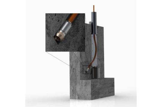
But the wells, which reach several thousand meters deep, entail both significant costs and risks at the same time. The risk of being wrong and finding nothing (what experts call the exploration risk) is about 30 percent. That is what the experts at the Fraunhofer Research Institution for Energy Infrastructures and Geothermal Systems IEG in Bochum want to change. Their idea is to use a mini-drill to perforate the area around the borehole in a radius of 50 meters and hydraulically connect the surrounding water-filled cracks and fractures to the borehole. This opens the way for the water to flow into the production well from where it can be pumped up.
Secondary drilling explores the surrounding area
The micro turbine drilling (MTD) technology was developed by Niklas Geißler, who performs research at the Fraunhofer IEG in Bochum and the Fraunhofer-Chalmers Research Center for Industrial Mathematics FCC in Sweden. "Wells that reach several kilometers into the earth's crust cost millions of euros. Additional branches from the main well using MTD increase the catchment area for hot water and the exploration risk significantly decreases," explains Geißler.
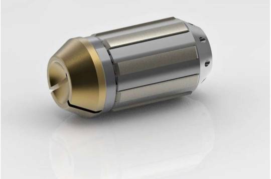
The key to MTD is a compact micro drilling turbine which is equipped with a special drill bit. It is very small, measuring just 3.6 centimeters in diameter and 10 centimeters in length. The micro turbine is attached to a high-pressure hose, through which it is powered by up to 200 liters of water per minute at an inlet pressure of about 100 bar, which makes the bit rotate. The bit consists of a tungsten carbide matrix with incorporated diamond grains and grinds into the rock at up to 80,000 rotations per minute. Therefore, it is especially suited for hard, crystalline rocks like granite. Furthermore, it is also capable of drilling steel. That is important because wells are usually lined with steel casing for better stability. Without changing the drilling tool, the MTD can first drill the steel casing and then the rock in a single step. "We can drill two to three meters in one hour. The water that powers the micro turbine serves as both a coolant, so the drill doesn't get too hot, and also flushes the hole to remove the drill cuttings," Geißler says. There have been similar technologies using pressurized water in the past, such as radial jet drilling. However, until now only soft rock could be drilled using those technologies. For geothermal energy in particular a method is needed to drill through the hard rock in which geothermal reservoirs are often found.
04/01/2022
0 notes
Text
Working Principle And Characteristics Of Stainless Steel Ball Valve
The stainless steel ball valve can be closed tightly with only a 90-degree rotation and a small torque. The completely equal internal cavity of the valve provides a straight flow channel with little resistance for the medium. The main feature of the ball valve is its compact structure, easy to operate and maintain. The stainless steel ball valve can be used to control the flow of various types of fluids such as air, water, steam, various corrosive media, mud, oil, liquid metal and radioactive media. The ball valve body can be integral or combined. This type of valve should generally be installed horizontally in the pipeline. Stainless steel ball valve classification: stainless steel pneumatic ball valve, stainless steel electric ball valve, stainless steel manual ball valve. Stainless steel ball valve materials are divided into 304, 316, 321 stainless steel ball valves.
Working principle
The working principle of the ball valve is to make the valve unblocked or blocked by rotating the valve core. The ball valve switch is light, small in size, can be made into a large diameter, reliable in sealing, simple in structure, easy to maintain, the sealing surface and the spherical surface are often closed, and it is not easy to be eroded by the medium, and it is widely used in various industries.
The ball valve and the plug valve belong to the same type of valve. Only its closing part is a sphere. The sphere rotates around the center line of the valve body to achieve opening and closing.
The ball valve is mainly used to cut off, distribute and change the flow direction of the medium in the pipeline. The ball valve is a new type of valve that is widely used.
Advantage of stainless steel ball valve
1. The fluid resistance is small, and its resistance coefficient is equal to that of a pipe section of the same length.
2. Simple structure, small size and light weight.
3. It is tight and reliable, and the sealing surface material of the ball valve is widely used in plastics, with good sealing performance, and it has also been widely used in vacuum systems.
4. It is easy to operate and open and close quickly. It only needs to rotate 90° from fully open to fully closed, which is convenient for remote control.
5. The maintenance is convenient, the structure of the ball valve is simple, the sealing ring is generally movable, and it is convenient to disassemble and replace.
6. When fully open or fully closed, the sealing surface of the ball and the valve seat is isolated from the medium, and the medium will not cause erosion of the valve sealing surface when the medium passes.
7. It has a wide range of applications, with a diameter ranging from a few millimeters to a few meters, and can be applied from high vacuum to high pressure.
Ball valves have been widely used in petroleum, chemical industry, power generation, papermaking, atomic energy, aviation, rockets and other departments, as well as people's daily life.
Features
Stainless steel ball valve are divided into O-shaped ball valves and V-shaped ball valves. The O-type ball valve adopts a floating structure, the core is a precision casting, the surface is plated with hard chromium, and the valve seat is made of reinforced polytetrafluoroethylene. The diameter of the flow channel is the same as that of the pipe. Leakage, generally used as on-off valve, especially suitable for high-viscosity, fiber-containing, granular media; V-shaped ball valve adopts a fixed structure, with a V-shaped cut on the core, which can achieve proportional adjustment, and the flow characteristics are approximately equal percentages.
Depending on the process equipment, pneumatic or electric can be selected to form pneumatic ball valves and electric ball valves. The pneumatic ball valve must be equipped with a valve positioner to achieve proportional adjustment, and the electric ball valve must be equipped with electronic electric actuators or servo amplifiers to achieve proportional adjustment. Wait.
From the material point of view, it can be divided into: carbon steel ball valve, stainless steel 304 ball valve, 316 ball valve and copper ball valve
In terms of application, it can be divided into: high pressure ball valve and low pressure ball valve
High-pressure ball valve: Mainly used in petroleum, natural gas, hydraulic oil, construction machinery and other industries
Low-pressure ball valve: Mainly used in non-corrosive pipelines such as water as the medium!
0 notes
Text
Service Your Boilers Before Winter Arrives
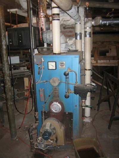
As HVAC professionals begin getting their sleepy boilers ready for the upcoming heating season, they know that the first few weeks can be hectic, as dormant boilers are lit and unexpected startup problems pop up all over. It’s typically a time with some long days and a steady stream of calls from residents and building operators.
Professionals who’ve been doing this for a while, know that even if a boiler has been professionally inspected and serviced during the summer months, idle heating systems are still susceptible to both sediment and corrosion. Sediment settles out of the cold motionless water and compacts in pumps and valves, and of course as Mr. Young famously said, “rust never sleeps.”
The physics of heating system inactivity conspires to create a rich set of winter startup problems for commercial heating professionals. As a premiere manufacturer of advanced heating control systems, the experts at Heat-Timer® have seen their share of these startup problems, and taught building managers a few tricks for using our controls and room sensors to diagnose these issues.
1. Preventing Pump Problems. Because of this summer’s accumulation of sediment and rust, pumps are one of the first things that a technician checks when they turn on the boiler. Often a pump won’t start because the impeller is embedded in sediment. If the pump does start, it may leak through dried out seals. This often leads to a pump disassembly, cleaning and rebuild, or full pump replacement.
This expensive fall pump ritual can be prevented with a little exercise. A pump lead lag controller like the Heat-Timer® PLL can exercise boiler pumps by running them for a short period every week during the off-season, keeping seals wet and flushing out sediment. The Heat Timer® PLL also has low flow alarms which when interfaced to a Platinum series controller, can alert the boiler service company or building manager that there is a pump failure at any time during the heating season. Often these problems can be diagnosed and resolved without a visit to the boiler room, thanks to our BuildingNet® interface or mobile phone app.
2. Oil Fired Boilers – For oil fired boilers, clogged fuel filters can be another start-up problem as a summer’s accumulation of black sludge is stirred up and sucked into the filter when the oil tank is filled in the fall. This can cause hard to diagnose boiler lockouts as the burner is intermittently starved for fuel unless that oil filter is monitored with a vacuum sensor like Heat Timer’s Oil Filter Monitoring Kit. An oil filter monitor connected to a Platinum controller can give a building manager plenty of warning that a fuel filter needs to be replaced, so that it can be changed at the next regular boiler service, rather than during a late-night emergency call after a boiler lock-out.
3. Plumbing Decay – While pumps and filters are the obvious problem areas during boiler start up because they are right there out in the open, there are invisible problems in the boiler room too. Pipes, condensate tanks and the boilers are eternally and invisibly rusting from the inside out. Boiler tube leaks are common start-up problems on older boilers. Iron pipes can suddenly develop pinhole leaks. Steam traps can fail to close properly. Even when these leaks are as obvious as a puddle on the floor, it can be days before someone goes into the boiler room and notices it. On the other hand a leak from a steam line or steam trap can be hard to see even if a service technician is looking for it, and water leaking from inside the boiler may evaporate and go up the stack, but not before causing further corrosion problems in the burner and the flue ducting.
Fortunately, the days (and nights) of discovering water leaks only after the sump pump alarm goes off are long gone. Sensitive boiler feedwater meters connected to BuildingNet® through a Platinum controller continuously measure boiler make-up water usage. Building managers can use BuildingNet’s trending tools to visualize long term changes in boiler water usage week to week or season to season, helping identify water leaks while they are still small and inexpensive to fix rather than after they have flooded the boiler room, shutting down the boiler and damaging equipment.
Heat-Timer® Controls Save Money and Maintenance Headaches.
There is a lot to keep an eye on in those first few weeks of boiler operation, especially if you are responsible for multiple buildings. Knowing that your boiler controller has your back, monitoring everything going on in the boiler room can make waking up the boilers a lot less stressful. Heat-Timer® has been helping boiler service professionals wake up the boilers for over 80 years with a deep toolkit of controllers, sensors and alarms.
If servicing the boilers keep you awake at night, consider upgrading to Heat-Timer’s Platinum controller with a BuildingNet® remote interface.
Original content posted on https://www.heat-timer.com/service-your-boilers-before-winter-arrives/
#Blog#Platinum Controllers#steam boiler system#steam boiler replacement#steam boiler installation#steam boiler heating system#Steam Boiler Controls
0 notes
Text
Making process control valve choices
Today’s process control valves offer an ever wider range of features and benefits for industries that require precise control over fluids, steam and other gases. With so many control valves to choose from it is important to establish the features that will deliver the most cost-effective design for a particular application.
Control valves are used to manage the flow rate of a liquid or a gas and in-turn control the temperature, pressure or liquid level within a process. As such, they are defined by the way in which they operate to control flow and include globe valves, angle seat, diaphragm, quarter-turn, knife and needle valves, to name a few. In most cases the valve bodies are made from metal; either brass, forged steel or in hygienic applications 316 stainless steel.
Actuators will use an on-board system to measure the position of the valve with varying degrees of accuracy, depending on the application. A contactless, digital encoder can place the valve in any of a thousand positions, making it very accurate, while more rudimentary measurements can be applied to less sensitive designs.
One of the main areas of debate when specifying globe control valve is determining the size of the valve required. Often process engineers will know the pipe diameter used in an application and it is tempting to take that as the control valve’s defining characteristic. Of greater importance are the flow conditions within the system as these will dictate the size of the orifice within the control valve. The pressure either side of the valve and the expected flow rate are essential pieces of information when deciding on the valve design.
Inside the valve body, the actuator design is often either a piston or a diaphragm design. The piston design typically offers a smaller, more compact valve which is also lighter and easier to handle than the diaphragm designs. Actuators are usually made from stainless steel or polyphenolsulpide (PPS), which is a chemically-resistant plastic. The actuator is topped off by the control head or positioner.
Older, pneumatically operated positioners had a flapper/nozzle arrangement and operated on 3-15psi, so no matter what the state of the valve, open closed or somewhere in between, the system was always expelling some compressed air to the atmosphere.
Compressed air is an expensive commodity, requiring considerable energy to generate and when a manufacturing line is equipped with multiple process control valves all venting to the atmosphere, this can equate to a considerable waste of energy. It is important to not only establish the most appropriate valve design, but also a cost-effective solution that takes account of annual running costs.
Modern, digital, electro-pneumatic valves that use micro-solenoid valves to control the air in and out of the actuator have introduced significant improvements for operators. This design means that while the valve is fully open, fully closed or in a steady state, it is not consuming any air. This, and many other engineering improvements, have made substantial advances in both economy and precision.
Flexible designs
Valve seats can be interchangeable within a standard valve body, which allows the valve to fit existing pipework and the valve seat to the sized to the application more accurately. In some cases, this can be achieved after the valve has been installed, which would enable a process change to be accommodated without replacing the complete valve assembly.
Selecting the most appropriate seal materials is also an important step to ensure reliable operation; Steam processes would normally use metal-to-metal seals, whereas a process that included a sterilization stage may require chemically resistant seals.
Setting up and installing a new valve is now comparatively easy and much less time-consuming. In-built calibration procedures should be able perform the initial setup procedures automatically, measuring the air required to open and close the valve, the resistance of the piston seals on the valve stem and the response time of the valve itself.
Improving safety
Control valves should be specified so they operate in the 40-85% range so if the valve is commanded to a 10% setting, it can detect if something has potentially gone wrong with the control system and the best course of action is to close the valve completely. If the valve is commanded to a position of 10% or less this can cause very high fluid or gas velocities, which have damaging effects on the system and cause considerable noise and damage to the valve itself.
Modern control functionality can offer a solution that acts as a safety device to prevent damage to the process pipework and components. By building in a fail-safe mechanism, any valve position setting below a pre-set threshold will result in the valve closing completely, preventing damage to the surrounding system.
Control inputs can also include safety circuits to ensure safe operating conditions within the process equipment. For example, if an access panel on a vessel containing steam is opened, an interlock switch will open and the valve controlling the steam supply to the vessel can be automatically closed, helping mitigate any risks.
Improving reliability
Many process control environments offer less than ideal conditions for long-term reliability. Moisture-laden atmospheres, corrosive chemicals and regular wash-downs all have the capacity to shorten the service life of a process Self regulating control valve. One of the potential weaknesses of the actuator is the spring chamber where atmospheric air is drawn in each time the valve operates.
One solution is to use clean, instrument air to replenish the spring chamber, preventing any contamination from entering. This offers a defense against the ingress of airborne contaminants by diverting a small amount of clean control air into the control head, maintaining a slight positive pressure, thus achieving a simple, innovative solution. This prevents corrosion of the internal elements and can make a significant improvement to reliability and longevity in certain operating conditions.
While choosing the most appropriate process control valve can be a complex task, it is often best achieved with the assistance of expert knowledge. Working directly with manufacturers or knowledgeable distributors enables process control systems to be optimized for long-term reliability as well as precision and efficiency.
Damien Moran is field segment manager, Hygienic – Pharmaceutical at Bürkert. This article originally appeared on the Control Engineering Europe website. Edited by Chris Vavra, associate editor, Control Engineering, CFE Media and technology, [email protected].
Control valves are generally present whenever fluid flow regulation is required. The three way and angle control valve reliability is critical to the control quality and safety of a plant. An improved dynamic and static valve behaviour would have a major impact on the process output. In order to assess the dynamic performance of the control valve, a computer model of an electro-hydraulic control valve is developed. And the control valve characteristics are investigated through the use of mathematical simulations of the control valve dynamic performance. The results show that the electro-hydraulic driven control valve, which is developed to regulate the mixed-gas pressure in combined cycle power plant, can meet the challenge of the gas turbine.
Control valves play important roles in the control of the mixed-gas pressure in the combined cycle power plants (CCPP). In order to clarify the influence of coupling between the structure and the fluid system at the control valve, the coupling mechanism was presented, and the numerical investigations were carried out. At the same operating condition in which the pressure oscillation amplitude is greater when considering the coupling, the low-order natural frequencies of the plug assembly of the valve decrease obviously when considering the fluid-structure coupling action. The low-order natural frequencies at 25% valve opening, 50% valve opening, and 75% valve opening are reduced by 11.1%, 7.0%, and 3.8%, respectively. The results help understand the processes that occur in the valve flow path leading to the pressure control instability observed in the control valve in the CCPP.
1. Introduction
The steel mills generate vast amounts of blast furnace gas (BFG) and coke-oven gas (COG) in the production. In order to reduce the environmental pollution, some steel mills mix BFG with COG and build combined cycle power plants (CCPP) to make use of the gas [1]. For the normal operation of CCPP, the pressure of mixed gas delivered to the gas turbine should be kept in a steady range.
In CCPP, control valves play important roles in the control of the mixed-gas pressure. The signal of mixed-gas pressure measured using the pressure meter is compared to the signal of the desired pressure by the controller. The controller output accordingly adjusts the opening/closing actuator of the control valve in order to maintain the actual pressure close to the desired pressure. The opening of the control valve depends on the flow forces and the driving forces of the control-valve actuator, while the flow forces and the driving forces are affected by the valve opening. Therefore, there is strong coupling interaction between the fluid and the control valve structure.
According to Morita et al. (2007) and Yonezawa et al. (2008), the typical flow pattern around the Knife Gate Valve is transonic [2, 3]. When pressure fluctuations occur, large static and dynamic fluid forces will act on the valves. Consequently, problematic phenomena, such as valve vibrations and loud noises, can occur, with the worst cases resulting in damage of the valve plug and seal [4]. In order to understand the underlying physics of flow-induced vibrations in a steam control valve head, experimental investigations described by Yonezawa et al. (2012) are carried out. Misra et al. (2002) reported that the self-excited vibration of a piping system occurs due to the coincidence of water hammer, acoustic feedback in the downstream water piping, high acoustic resistance at the control valve, and negative hydraulic stiffness at the control valve [5]. Araki et al. (1981) reported that the steam control-valve head oscillation mechanism was forced vibration, while self-excited vibration was not observed [6].
Those studies cited previously are mainly aimed at the modeling of the self-excited vibration, the analysis of vibration parameters stability, and so on [7–11]. Whereas, the studies on the influence of nonlinear fluid-structure coupling of control valve on the valve control characteristics, such as the pressure regulation feature, are still very limited [12–17]. In the CCPP, the valve control characteristics affected by the fluid-structure coupling are particularly important for the stability of the mixed-gas pressure control. It has not been uncommon to see that the instability of the mixed-gas pressure causes a severe disturbance or even an emergency shutdown of the whole plant, and the handling of such an emergency often becomes a source of new problems and confusion. In this paper, numerical investigations are carried out to clarify the influence of fluid-structure coupling of control valve on not only the flow field but also the gas pressure regulation and the natural frequency changes of the control valve. This study helps understand the processes that occur in the valve flow path leading to the mixed-gas pressure pulsations, which is valuable for the pressure stability control of the mixed gas in the CCPP.
0 notes
Text
Control Valve
This valve controls the expulsion of oil from the spring side of the second gear band servo piston at speeds in the region of 60 km/h. The time period for oil to exhaust then depends upon the governor pressure varying the effective exhaust port restriction. Line pressure oil from the spring side of the second gear band servo piston passes through a passage leading to the 3–2 kickdown valve annular groove and from there to the 2–3 shift valve annular groove. Here some oil exhausts out from a fixed restriction while the remainder passes via a passage to the 3–2 control valve. As the vehicle speed approaches 60 km/h the governor pressure rises sufficiently to force back the 3–2 control valve piston, thus causing the wasted (reduced diameter) part of the control valve to complete the exhaustion of oil.
Valves control the gas flowing into and out of the engine cylinder. The camshaft and valve spring make up the mechanism that lifts and closes the valves. The valve train determines the performance characteristics of four-stroke-cycle engines.
There are two types of valve, inlet and exhaust. Figure 6.1 shows an exhaust valve. An inlet valve has a similar form. The commonly used poppet valve1 is mushroom-shaped. Figure 6.2 illustrates the parts of the valve. A cotter (not shown in Fig. 6.2) which fixes the valve spring retainer to the valve, is inserted into the cotter groove.Alumina valves and seats
corrosion resistant control valve come in many forms: butterfly valve, ball and seat valve, disk-valve, piston-sleeve metering valve, and dart valve, to name but a few. Alumina has been used in many industrial valves. Water faucet valves of the standard disk-on-disk configuration are very common and are discussed in Section 12.2.8. Since they share almost all the same features of pump rotary valves.
Dart valve plugs and seats are a fluid-flow-control component. When used in the mineral processing industry, or in other industries where slurries, or corrosive liquids, or corrosive slurries are flowing, these valve/plug systems need to be highly wear resistant, especially the plug which can be particularly exposed to the flow of the erosive/corrosive fluids. An example of a dart valve and plug is shown in Fig. 12.17. Alumina valves are an increasingly common technology in general.
One revolution of the camshaft gives the amount of valve lift shown in Fig. 6.3. The valve stem moves in the valve guide and also revolves slowly around the stem. The revolving torque is generated by the expansion and contraction of the valve spring.
An engine basically needs one inlet valve and one exhaust valve per cylinder but most modern engines use four valves per cylinder. This multi-valve configuration raises power output, because the increased inlet area gives a higher volume of gas flow. Contemporary five-valve engines use three inlet valves and two exhaust valves to increase trapping efficiency at medium revolutions.
Figure 6.4 summarizes the functions of the valve. The shape of the neck, from the crown to the valve stem, ensures that the gas runs smoothly. The valve typically receives an acceleration of 2000 m/s2 under high temperatures. Valves must be of light weight to allow the rapid reciprocating motion.
With the single seated control valve lowered, the hydraulic pump is applied to bring the bottom plate of the mould to the lower limit. The separator is then lowered into the mould and fed with the shell and the inner core materials. The vibrator is switched on for 5 s to consolidate the content. The space created by consolidation is topped up. The vibrator is switched on again while the separator is extracted from the moulds. The top of the content of mould is flattened, and the mould lid closed and clamped. With the single seated balanced control valve raised, the hydraulic pump is engaged to stress the content to the desired compaction pressure, which was readable on the gauge. The mould lid is opened and with the control valve raised, the block is ejected from the mould.
Typical specimens of hollow SCEB produced with the mechanical kit are shown in Fig. 13.8. The two holes reduced the overall weight of block by 24%. It is also anticipated that the hollowed nature of the block will accommodate any expansion of the inner core material.
Active or passive valves control the flow of samples and reagent through the different steps. Passive valves are able to control fluid movement in a limited way, for example, by allowing flow in one direction through a channel but not in the other one as described above On the other hand, active valves need to be actuated externally using a smart control strategy that typically makes use of sensors to have feedback (Schumacher et al., 2012). Actuation of these valves is very often performed by electrical means, for example, by having a current flow through a copper line and then heating a chamber filled with air that expands and deflects a flexible membrane, which closes a microfluidic channel. Sometimes the deformation of such a membrane is directly performed by using pressurized air coming from an external source, making the valve actuation purely pneumatic instead of electrothermal.
The open tank and multi hole single seated control valve arrangement (Fig. 4) used here together with the 3% cavitation criterion in Fig. 2 is considered to be an industry-based and reliable method for determination of NPSHR in the pump best efficiency region, ISO [4]. More elaborate closed vacuum tank arrangements are used by pump manufacturers to establish NPSHR-curves for water. The measured NPSHR-values obtained here for water (Fig. 5) were about 10% larger than values from the GIW-pump curves. This means that the slurry NPSHR-results in Fig. 5 were about 1.5 times the water values from the pump curves. The scatter may represent the increased cavitation intensity of flow disturbances in an open tank system when compared to a closed tank arrangement.
Experimental closed tank results for sands with average particle sizes of 0.18 and 0.5 mm in pumps with impeller diameters of 0.35 and 0.6 m, respectively, were reported by Herbich [5]. Slurry densities were up to about 1400 kg/m3. It was found that the NPSHR-values (expressed in m of slurry) were similar to the water values, independent of the slurry density. Similar results were also reported by Herbich [5] and Ladouani et al. [6] for non-settling clay-silt slurries with densities of up to 1300 kg/m3 in pumps with impeller diametres less than 0.275 m. Ladouani et al. [6] used an open-tank loop arrangement. Detailed inspection of their data indicates that the independence of the slurry density on NPSHR was limited to flow rates smaller than about 70% of the best efficiency point (BEP). With larger flow rates, NPSHR increased with increasing slurry densities, giving values from 1 to about 2 times the water values in the BEP-region.
The results obtained here were for flow rates close to BEP. Field NPSHR results agreed reasonably well with the laboratory data for the same type of pump pumping phosphate (Fig. 1) at about 500 rpm for flow rates of about 75% of BEP, Addie et al. [7]. In practice, it is therefore reasonable to assume that the laboratory NPSHR-results obtained here are applicable for the flow rate region where most slurry pumps operate today (0.75 to 1.0 of BEP).
Balancing (Fig. 12.15(a and b)) With the compressed air passing to the brake actuator chambers, air pressure is built up beneath the upper and lower pistons. Eventually the upthrust created by this air pressure equals the downward spring force; the pistons and valve carrier lift and the inlet valves close, thus interrupting the compressed air supply to the brake actuators. At the same time, the exhaust valves remain closed. The valves are then in a balanced condition with equal force above an below the upper piston and with equal air pressure being held in both halves of the brake line circuits.
Pushing the treadle down still further applies an additional force on top of the graduating spring. There will be a corresponding increase in the air pressure delivered and a new point of balance will be reached.
Removing some of the effort on the foot treadle reduces the force on top of the graduating spring. The pistons and valve carrier will then lift due to the air pressure and piston return springs. When this occurs the inlet valves remain closed and the exhaust valves open to exhausting air pressure from the brake actuators until a state of balance is obtained at lower pressure.
Releasing brakes (Fig. 12.15(b)) Removing the driver's force from the treadle allows the upper and lower piston and the valve carrier to rise to the highest position. This initially causes the inlet/exhaust valves to close their inlet seats, but with further upward movement of the pistons and valve assembly both exhaust valves open. Air from both brake circuits will therefore quickly escape to the atmosphere thus fully releasing the brakes.
It’s difficult to obtain the flow of sequential valves due to lack of measurement data. The main steam is separated through the four valves and then enter into corresponding group of nozzles. The only flow data we can get from measurement is the main steam. Although there are various formulas to calculate the theoretical flow of valves, flow characteristics of valves are required to obtain the actual flow. However, the flow characteristics of sequential valves are not available through experiment. So a calculation method rely on operation data is necessary.
0 notes