#flex PCB connector
Explore tagged Tumblr posts
Visit Tumblr Blog
Explore Tumblr blogs with no restrictions, modern design and the best experience.
Last Seen Tumblr Blogs


Fun Fact
69% of Tumblr users are millennials.
Text
XPCB Limited - Your Premier Flex PCB Supplier and Manufacturer
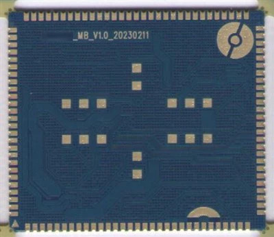
XPCB Limited is proud to showcase its expertise with the production of a 10-layer flexible PCB, designed for a top-class flex PCB connector. This high-performance circuit board exemplifies the level of precision and reliability that XPCB brings to all its projects. With years of experience in flexible PCB manufacturing, XPCB ensures each product is meticulously designed to meet the most stringent industry standards.
For More Information: https://www.slideshare.net/slideshow/xpcb-limited-your-premier-flex-pcb-supplier-and-manufacturer/275037546
0 notes
Text
Navigating the Future of Electronics with Rigid-Flex and Taconic PCB Manufacturers
Today’s Printed Circuit Boards (PCBs) are much more flexible and advanced than the first rigid versions. Compact devices with great capabilities and multiple features have earned popularity in the electronics industry, leading to the rise of Rigid-Flex PCBs and Taconic PCBs. The use of these technologies enables unique designs, improves how long the device works, and maintains good electricity flow. Rigid-flex PCB Manufacturers can move and also keep their form, similar to how rigid boards function. They particularly shine in high-speed or RF and microwave applications. Dependable and effective products rely greatly on what electronics do.
Rigid-Flex PCBs: Hybrid Structure with High Functionality
Rigid-Flex PCBs take attributes from both stiff and flexible PCBs and merge them into one board. As a result, rigid and flexible boards no longer need connectors and cables, letting us make assemblies that are lighter and more space-saving. You can find these boards in smartphones, medical devices used on patients, military systems and aerospace devices. They are suited for use in places that require resistance to vibration and bending due to machines. In manufacturing, various layers are made and bonded together using very accurate methods. Therefore, it is only experienced manufacturing companies that can keep products of constant quality and performance.
Key Advantages of Rigid-Flex PCB Manufacturers
Important benefits of using well-known Rigid-flex PCB Manufacturers are their excellent design aid and advanced methodologies. They depend on laser direct imaging for precise work and optical inspection that finds problems in the early stage. Tests using temperature fluctuation and electrical overload guarantee that the product will function in any extreme condition. Manufacturers typically boost efficiency by assisting with design changes that lower the number of components and simplify assembly. In addition, they guarantee that flexible circuit boards meet all IPC standards for quality. Because they are involved in developing products and moving them into mass production, they help make the process more efficient.
Taconic PCBs: High-Frequency Performance Excellence
Taconic PCB Manufacturers are produced from proprietary PTFE-based laminates designed by Taconic with low dielectric loss and thermal stability. These boards are the preferred option for RF, microwave, and high-speed digital designs. They are most prevalent in satellite communications, radar systems, 5G base stations, and aerospace communication modules. Taconic laminates have low signal attenuation and superior dimensional stability. They exhibit moisture resistance as well as heat tolerance, which makes them dependable in extreme working environments. Production using these laminates demands proficiency in drilling, plating, and multilayer bonding because of their special properties.
What to Expect from a Taconic PCB Manufacturers
The best Taconic PCB Manufacturers must possess extensive experience in working with high-frequency laminate material. It involves strict impedance control, surface preparation, and low-loss transmission line engineering. Cleanroom facilities, specially designed PTFE-compatible equipment, and precise lamination procedures are necessary for high-quality output. The producers may perform RF testing and thermal profiling to ensure circuit integrity. They also guide customers on stack-up selection as well as PCB layout according to end-use frequency requirements. By maintaining compliance with IPC and MIL-spec specifications, these companies ensure the critical applications' performance and safety.
Comparing Rigid-Flex and Taconic PCBs
Although both are sophisticated PCBs, Rigid-Flex and Taconic PCBs are for different technical applications. Rigid-Flex is prized for mechanical flexibility, whereas Taconic leads for signal transmission at high speeds. Rigid-Flex boards simplify systems and minimize space utilization in cramped enclosures, while Taconic boards maintain signal purity in communication networks. The components and manufacturing methods are quite different, as are the final-use applications. The two are chosen based on physical space, frequency range, and exposure to the environment. Designers will often talk to both varieties of manufacturers to match their circuit requirements with the appropriate solution.
Conclusion
As innovation speeds up in electronics, the need for Rigid-flex PCB Manufacturers and Taconic PCBs keeps increasing. Such technologies facilitate the development of lighter, faster, and more efficient devices across industries. With increasingly sophisticated design challenges, collaborating with an experienced manufacturer is crucial. BS Interconn Hong Kong Co., LIMITED differentiates itself by providing quality-oriented, customer-centric PCB manufacturing services. Whether you're creating a next-generation medical wearable or a state-of-the-art RF device, selecting a reliable Rigid-Flex or Taconic PCB producer guarantees that your product will outperform and outlast the competition.
#Rigid-flex PCB Manufacturers#Taconic PCB Manufacturers#flexible circuit boards#high-frequency PCB#RF PCB solutions#microwave PCBs#PTFE laminates#hybrid PCB design#aerospace PCB#medical device PCBs#5G PCB manufacturer#signal integrity PCB#low dielectric PCB#high-speed PCB#multilayer PCB assembly#IPC compliant PCBs#MIL-spec PCBs#advanced PCB manufacturing#Taconic laminate PCB#Rigid-Flex technology
1 note
·
View note
Text
Rigid-Flex PCB Design Guidelines: Ensuring Reliability and Manufacturability
Designing a Rigid-Flex PCB requires more than just combining rigid and flexible sections into one board. It involves careful planning of layout, layer structure, materials, and mechanical constraints to ensure the final product is reliable, manufacturable, and cost-effective.
Below are key guidelines every engineer should follow when designing Rigid-Flex PCBs.
1. Define Rigid and Flex Zones Early
Clearly identify the rigid and flex areas during the initial layout phase. Flex regions should only exist where necessary — overdesigning with too much flex area increases cost and complexity.
Each zone should be planned based on:
Mechanical movement (bending/folding)
Component placement needs
Connector and housing locations
Avoid placing unnecessary flex areas just for routing convenience unless absolutely needed.
2. Maintain Symmetrical Layer Stack-Up
An unbalanced stack-up can lead to warping, twisting, or delamination during lamination or reflow.
Keep the number and thickness of layers symmetrical around the centerline of the rigid section.
Use dummy traces or copper balancing layers to achieve mechanical balance if needed.
Plan separate stack-ups for rigid and flex areas, but ensure transition is smooth.
3. Protect the Flex Area
The flexible section is vulnerable to cracking and wear if not designed carefully.
Never place vias, pads, or components in the flex zone.
Maintain generous spacing between traces in the flex area to reduce mechanical stress.
Avoid 90° corners and sharp transitions — use smooth curves or teardrops for trace routing.
Use coverlay (instead of solder mask) to protect the flex area from mechanical damage.
4. Follow Proper Bending Design Rules
The flex section must withstand multiple bends over its lifetime. Improper bending design can cause trace cracking, delamination, or copper fatigue.
Minimum bend radius should be 6 to 10 times the flex thickness for dynamic bends.
For static (one-time) bends, 3 to 6 times the thickness may be acceptable.
Use curved traces in the bend area to avoid concentration of stress.
Keep traces perpendicular to the bend axis wherever possible.
5. Stiffener Usage
Stiffeners are added in flex areas to provide mechanical support for connector pads or component locations.
Use FR4, polyimide, or stainless steel stiffeners depending on mechanical requirements.
Clearly define stiffener thickness and position in the mechanical drawings.
Do not overlap stiffeners with bend areas unless absolutely required.
6. Routing and Trace Layout
Trace layout impacts both electrical and mechanical performance.
In the flex region, use wide, evenly spaced traces to reduce stress.
Avoid overlapping traces on top and bottom layers in bend areas.
Do not route traces over the transition zone between rigid and flex — leave a clearance buffer.
Maintain consistent impedance and routing lengths for high-speed signals.
7. DFM Considerations
Design for Manufacturability (DFM) is critical for Rigid-Flex PCBs due to the multiple lamination cycles and tighter tolerances.
Ensure design files clearly mark flex/rigid regions and bending direction.
Avoid complex via structures (like stacked or blind/buried vias) near flex zones.
Confirm with the PCB manufacturer about acceptable layer counts, material systems, and bend performance.
Work closely with your fabricator early in the design process to avoid costly revisions.
8. Assembly Planning
Plan your PCB assembly process around the flex structure.
Use support fixtures or carrier panels during SMT to keep the board flat.
Make sure flex areas are protected during handling and soldering.
Define handling instructions clearly if the flex zone should not be bent before final assembly.
Final Thoughts
Rigid-Flex PCBs offer unmatched versatility for compact, high-performance designs — but only when designed correctly. By following key guidelines for stack-up, routing, bending, and assembly, designers can ensure their boards are reliable, manufacturable, and optimized for long-term success.
Collaborate closely with your PCB manufacturer and assembly house throughout the design process to turn your concept into a robust, production-ready product.
0 notes
Text

Rigid-flex PCB: All connectors or component assembly occurs on the rigid layer, and sometimes line support, strain buffering and component support are also required.
#pcb#flex pcb#rigid-flex pcb#flex circuit pcb#flexible pcb board#flexible circuit board#fpcway#fpcway.com#www.fpcway.com#today on tumblr
0 notes
Text
Understanding the Differences Between Rigid, Flex, and Rigid-Flex PCBs

Introduction
In the world of electronics manufacturing services, PCBs (Printed Circuit Boards) are a critical component in nearly all electronic devices. From smartphones to medical devices, PCBs are the backbone of modern electronics. However, not all PCBs are created equal. Depending on the application, PCBs can be designed in various forms, such as rigid, flexible, or rigid-flex.
In this blog, we will delve into the differences between rigid, flex, and rigid-flex PCBs, helping you understand which type is best suited for your specific electronics manufacturing services needs.
1. Rigid PCBs: The Standard Choice
Rigid PCBs are the most common type of circuit boards used in electronics today. They are made from a solid, inflexible material such as FR4, which is a composite of fiberglass and resin. Rigid PCBs are typically used in applications where the circuit board will remain stationary and not be exposed to constant bending or flexing.
Key Features of Rigid PCBs:
Sturdy and Durable: Rigid PCBs are highly durable and can handle the demands of many different applications.
Cost-Effective: Due to their widespread use and simple design, rigid PCBs are often the most cost-effective option.
Common Applications: Rigid PCBs are commonly used in consumer electronics, automotive systems, and industrial equipment.
Benefits of Rigid PCBs:
Reliability: Rigid PCBs offer a solid foundation for electronic components, ensuring stable and reliable performance.
Ease of Assembly: The rigid structure makes it easier to assemble and mount electronic components, which is essential for mass production.
2. Flexible PCBs: Ideal for Compact and Portable Devices
Flexible PCBs are designed to be bent, twisted, and shaped to fit into compact or irregularly shaped enclosures. Made from flexible materials like Polyimide (PI) or PET (Polyethylene Terephthalate), flexible PCBs can be folded and flexed without breaking or damaging the circuitry.
Key Features of Flexible PCBs:
Flexibility: Flexible PCBs can bend and conform to different shapes, making them ideal for applications with space constraints.
Lightweight: Flexible PCBs are lightweight, which is important in portable devices.
Thin and Compact: These PCBs are thinner and more compact than rigid PCBs, offering more design flexibility.
Benefits of Flexible PCBs:
Space Efficiency: Flexible PCBs allow for smaller and more compact device designs.
Durability in Challenging Environments: These PCBs can withstand vibrations, shocks, and environmental stresses, making them ideal for wearables and medical devices.
Reduced Wiring: With flexible PCBs, designers can eliminate the need for multiple connectors and wiring, simplifying the design and improving reliability.
3. Rigid-Flex PCBs: A Hybrid Solution for Complex Designs
Rigid-flex PCBs combine the best features of both rigid and flexible PCBs. These PCBs are made by integrating rigid PCB sections with flexible PCB sections. The result is a hybrid design that offers the durability of rigid PCBs with the flexibility of flexible PCBs.
Key Features of Rigid-Flex PCBs:
Hybrid Design: Rigid-flex PCBs consist of both rigid and flexible sections, allowing for more complex and versatile designs.
High-Density Interconnects (HDI): Rigid-flex PCBs are often used in high-density applications where space is limited but performance requirements are high.
Compact and Reliable: The integration of both rigid and flexible components allows for high-density designs without sacrificing durability.
Benefits of Rigid-Flex PCBs:
Design Flexibility: Rigid-flex PCBs allow for intricate and compact designs while maintaining high performance and reliability.
Improved Durability: By combining both rigid and flexible sections, these PCBs are less prone to damage caused by flexing or mechanical stress.
Space Optimization: Rigid-flex PCBs can be folded and bent into tight spaces, making them ideal for applications such as smartphones, tablets, and medical devices.
4. Choosing the Right PCB Type for Your Application
When deciding between rigid, flex, and rigid-flex PCBs, it’s essential to consider your application’s specific requirements. Each type of PCB has its advantages and limitations, making it suitable for different use cases.
When to Choose Rigid PCBs:
If your application involves static electronics where the circuit board will remain stationary.
When cost is a major factor and the design does not require flexibility.
If the application involves consumer electronics, industrial systems, or automotive electronics.
When to Choose Flexible PCBs:
If your application requires compact or portable devices where space is limited.
When flexibility is needed for bending or folding the circuit board to fit into irregularly shaped enclosures.
If the application is in wearables, medical devices, or mobile electronics.
When to Choose Rigid-Flex PCBs:
When your application requires the best of both worlds—rigid sections for stability and flexible sections for space efficiency and durability.
In applications that involve high-density interconnects or complex geometries, such as smartphones, tablets, or advanced medical devices.
When flexibility is needed in some parts of the circuit board but rigidity is required in others.
Conclusion
Choosing the right type of PCB for your project depends on several factors, including size, flexibility, cost, and performance requirements. Whether you need the sturdiness of rigid PCBs, the flexibility of flexible PCBs, or the hybrid benefits of rigid-flex PCBs, each type plays a crucial role in the electronics manufacturing services landscape.
By understanding the differences between rigid, flex, and rigid-flex PCBs, you can make an informed decision about the best solution for your product, ensuring that it meets both design and performance requirements.
Ready to explore high-quality electronics manufacturing services for your PCB manufacturing needs? Reach out to a trusted manufacturer today to ensure reliable and cost-effective solutions.
Also read:
How to Choose the Right Electronics Manufacturing Services Partner for Your Project
Custom PCB Manufacturing for Niche Electronics Applications
Cost-Effective Strategies in Circuit Board Manufacturing Without Compromising Quality
How Global Supply Chain Challenges Are Impacting Circuit Board Manufacturing
#electronics manufacturing#electronics#circuit board manufacturing#pcb manufacturing#electronics manufacturing services
0 notes
Text

The advantages of rigid-flex PCB board
1). It can effectively save the space on the circuit board and eliminate the use of connectors
Because the FPCB and rigid pcb board has been combined, the space that originally needed to use the connector can be saved. For some circuit boards with high-density requirements, less connectors will be better. In this way, it also saves the cost of parts using the connectors. In addition, the space between the two boards can be made tighter by eliminating the need for connectors.
2). The signal transmission distance is shortened and the speed is increased, which can effectively improve the reliability
The traditional signal transmission through the connector is “circuit board→connector→flexible pcb board→connector→circuit board”, while the signal transmission of the rigid-flex PCB board is reduced to “rigid circuit board→flexible pcb board→rigid circuit board”, signal transmission distance between different media is shortened, and the problem of signal transmission attenuation between different media is also reduced. Generally, the circuit on the PCB board is made of copper, while the contact terminal of the connector is gold-plated, and the solder pin is fully tin-plated. Moreover, solder paste is required to be soldered on the circuit board, and the signal transmission between different media will inevitably be attenuated. If you switch to a rigid-flex PCB board, these media will become less, and the signal transmission ability can be relatively improved. For some products that require higher signal accuracy, it helps to improve their reliability.
3). Simplify product assembly and save assembly time
The use of a rigid-flex PCB board can reduce the man-hours for SMT parts, because the number of connectors is reduced. It also reduces the man-hours for assembly of the whole equipment, because it eliminates the assembly action of inserting the FPC board into the connector. It also reduces the cost of parts management and inventory, because the required parts is reduced, so the management cost becomes less.
Email Cynthia: [email protected] if you are interested in PCB and PCBA service.
0 notes
Text
What Makes Proto PCBs and Rigid Flex Circuit Boards Key to Efficient Electronics Manufacturing?
When an gadgets grows, the choice of printed circuit board (PCB) is critical for the usefulness, execution and lifetime of the last item. These components are instrumental in optimizing the generation prepare, empowering faster advancement cycles, and giving more strong, space-efficient plans. Understanding the parts of Proto PCBs and Rigid Flex Circuit Boards in cutting edge electronics can offer assistance manufacturers streamline their forms and progress item quality.
Proto PCBs: The Establishment of Prototyping and Innovation
Proto PCB, too known as prototype PCBs, serve as the to begin with cycle in the PCB improvement cycle. They are basic in the plan and testing stages of item improvement, advertising manufacturers a way to test circuits and components some time recently full-scale generation. Proto PCBs are regularly created in little amounts, permitting engineers to rapidly distinguish plan imperfections, troubleshoot issues, and refine the circuit layout.
One of the fundamental points of interest of Proto PCBs is the speed at which they can be fabricated and tried. Since they are utilized for prototyping, manufacturers can make fast cycles, guaranteeing that the last item is as optimized as conceivable. This flexibility permits companies to decrease advancement time, cut costs, and eventually bring items to showcase faster.
Additionally, Proto PCBs offer the advantage of flexibility in plan. They can be customized to meet the particular needs of a extend, whether that’s for a straightforward buyer gadget or a complex mechanical framework. With progressed manufacturing strategies, Proto PCBs can join high-density interconnects (HDI), fine-pitch components, and multi-layer plans, making them perfect for cutting-edge electronic products.
Rigid Flex Circuit Boards: A Idealize Mix of Rigid and Flexible Technologies
Rigid Flex Circuit Boards speak to a noteworthy progression in PCB design. As the title proposes, they combine the properties of both Rigid PCBs and Flexible circuits, making them profoundly flexible and space-efficient. These Boards are essentially utilized in applications where space is restricted, or the item requires a combination of both Rigid and Flexible connections.
One of the essential benefits of Rigid Flex Circuit Boards is their capacity to give high-density interconnection in compact spaces. These Boards can diminish the number of connectors and cables required in a framework, rearranging the by and large plan. This is especially valuable in businesses such as aviation, car, and restorative gadgets, where estimate, weight, and unwavering quality are vital factors.
Rigid Flex Circuit Boards coordinated Rigid PCB areas with Flexible segments, permitting for both inflexibility in particular regions and adaptability where essential. This crossover plan is perfect for applications that require both steadiness and the capacity to twist or crease in a few parts of the product.

Moreover, these circuit Boards are cost-effective in the long run. Whereas the beginning setup costs might be higher than standard PCBs, Rigid Flex Circuit Boards diminish the require for extra connectors, cables, and other components, driving to investment funds in both get together and upkeep. Their capacity to coordinated numerous capacities into a single board encourage decreases the complexity of the last design.
Enhancing Manufacturing Efficiency
Both Proto PCBs and Rigid Flex Circuit Boards contribute to the by and large proficiency of the gadgets manufacturing prepare. Proto PCBs speed up the prototyping stage, permitting companies to rapidly test and repeat on their plans. This diminishes the hazard of expensive blunders amid the mass generation stage and empowers manufacturers to meet tight deadlines.
On the other hand, Rigid Flex Circuit Boards streamline the last item plan, making a difference manufacturers decrease the number of components, streamline gathering, and upgrade item strength. By coordination both Rigid and Flexible components into a single board, Rigid Flex Circuit Boards make more compact and effective plans, which is a key advantage in today’s gadgets market.
In conclusion, Proto PCBs and Rigid Flex Circuit Boards play a significant part in making strides the effectiveness of gadgets manufacturing. They empower quicker prototyping, more dependable plans, and space-efficient arrangements, all whereas diminishing generation costs. As the request for more modern and compact electronic gadgets develops, these innovations will proceed to be at the cutting edge of development, guaranteeing that manufacturers can meet the challenges of present day gadgets generation.
0 notes
Text
Choosing the Right PCB: A Guide to Modern Circuit Board Technologies
Introduction: Why PCB Type Matters
Selecting the right PCB type is crucial for ensuring the performance, reliability, and cost-effectiveness of your electronic product. From the widely-used FR4 PCB to specialized solutions like flex rigid PCB, the choices are vast. This blog breaks down the major types of PCBs including copper PCB board, flex PCB, and metal core PCB to help guide your decision.
1. Copper PCB Board: Built for Performance
The copper PCB board is renowned for its high thermal and electrical conductivity. These boards are often used in applications requiring durability and high current carrying capacity, such as industrial machinery and automotive electronics. Their robustness makes them indispensable in harsh environments.
2. Flex PCB and Flex PCB Board Technology
A flex PCB, or flex PCB board, is constructed using materials that allow the board to bend during installation or use. These are ideal in devices where space and weight savings are critical, such as smartphones, medical tools, and aerospace components.
3. Versatility of the Flexible Circuit Board
The flexible circuit board excels in dynamic applications. Unlike traditional boards, it can bend, twist, and fold to fit into limited spaces, reducing the need for complex wiring and connectors. Its adaptability is a key benefit in wearables and miniaturized electronics.
4. Why FR4 PCB is a Go-To Choice
FR4 PCBs are made from a composite material consisting of woven fiberglass and epoxy resin. They offer excellent strength-to-weight ratio, moisture resistance, and electrical insulation. Common in computers and home appliances, FR4 remains a cost-effective and reliable option.
5. Metal Core PCBs for High-Power Needs
Metal core PCBs feature a metallic base for superior heat dissipation. They're the preferred choice in LED lighting systems, motor controllers, and heavy-duty applications. The ability to withstand thermal stress sets them apart from traditional PCB types.
6. Benefits of Flex Rigid PCBs
A flex rigid PCB merges flexibility with structural integrity, allowing engineers to design circuits that need both movement and stable anchoring. This is especially useful in foldable electronics, digital cameras, and instrumentation panels where space optimization is key.
7. Rigid Flex Circuit Boards in Compact Devices
A rigid flex circuit board provides both rigid support and flexible routing in a single board. This design reduces assembly time and improves signal integrity, making it ideal for high-speed data transfer devices and embedded systems.
8. Importance of Prototype PCB Assembly in Product Development
No matter how great the design, testing is vital. Prototype PCB assembly enables quick iterations and debugging before final production. Whether you're using a flex PCB or a metal core PCB, prototyping helps validate your concept, improve efficiency, and ensure a successful product launch.
Conclusion
Choosing the right PCB—from copper PCB board to rigid flex circuit board—depends on your project’s specific needs. Understanding the unique advantages of each type allows you to make informed decisions, streamline production, and deliver better-performing electronics. With the right PCB technology and proper prototype PCB assembly, you can bring even the most ambitious electronic designs to life.
0 notes
Text
Flexible PCB Manufacturer: The Key to Advanced Electronics Innovation
Introduction
The electronics industry is rapidly evolving, and Flexible PCB Manufacturer plays a crucial role in enabling cutting-edge innovations. From wearable devices to aerospace applications, flexible printed circuit boards (PCBs) provide unmatched adaptability, durability, and performance. This article explores the importance of flexible PCBs, their manufacturing process, applications, and how choosing the right Flexible PCB Manufacturer can make a significant difference in product development.
What Are Flexible PCBs?
Flexible PCBs are circuit boards made from bendable materials such as polyimide or polyester. Unlike rigid PCBs, they can twist, fold, and conform to unique shapes, making them ideal for modern electronics where space and weight are critical factors.
Key Advantages of Flexible PCBs
Space Efficiency – Their thin and lightweight design allows for compact electronic assemblies.
Durability – Resistant to vibrations and mechanical stress, making them suitable for harsh environments.
High Performance – Excellent thermal stability and signal integrity for high-frequency applications.
Cost-Effective Assembly – Reduces the need for connectors and additional wiring, lowering production costs.
The Role of a Reliable Flexible PCB Manufacturer
Choosing the right Flexible PCB Manufacturer is essential for ensuring quality, reliability, and performance. A reputable manufacturer will offer:
1. Advanced Manufacturing Techniques
A top-tier Flexible PCB Manufacturer utilizes cutting-edge processes such as:
Laser Drilling – Ensures precision in microvia formation.
Automated Optical Inspection (AOI) – Detects defects early in production.
High-Density Interconnect (HDI) Technology – Enables complex, multi-layer flexible circuits.
2. Material Expertise
The best manufacturers work with high-quality materials, including:
Polyimide Films – Known for heat resistance and flexibility.
Copper Foils – Provides excellent conductivity.
Adhesive Systems – Ensures strong bonding between layers.
3. Customization Capabilities
A skilled Flexible PCB Manufacturer can tailor designs to meet specific requirements, such as:
Dynamic Flex Circuits – For repeated bending applications.
Rigid-Flex PCBs – Combines rigid and flexible sections for complex assemblies.
High-Frequency Flexible PCBs – Optimized for RF and microwave applications.
Applications of Flexible PCBs
Flexible PCBs are used in a wide range of industries due to their versatility.
1. Consumer Electronics
Smartphones & Tablets – Enables slim designs and foldable screens.
Wearable Devices – Used in smartwatches and fitness trackers for comfort and flexibility.
2. Medical Devices
Implantable Devices – Flexible circuits are biocompatible and durable.
Diagnostic Equipment – Supports high-precision sensors and compact designs.
3. Automotive Industry
Electric Vehicles (EVs) – Used in battery management systems and LED lighting.
Advanced Driver Assistance Systems (ADAS) – Ensures reliable performance in tight spaces.
4. Aerospace & Defense
Satellites & UAVs – Lightweight and resistant to extreme conditions.
Military Communication Systems – Provides high reliability in mission-critical applications.
How to Choose the Best Flexible PCB Manufacturer
Selecting the right Flexible PCB Manufacturer involves evaluating several factors:
1. Experience & Reputation
Look for manufacturers with a proven track record in flexible PCB production. Customer reviews and industry certifications (e.g., ISO 9001, IPC standards) are good indicators of reliability.
2. Technical Support & Design Assistance
A top Flexible PCB Manufacturer offers design-for-manufacturability (DFM) feedback to optimize performance and reduce costs.
3. Quality Control & Testing
Ensure the manufacturer follows strict quality checks, including:
Electrical Testing – Verifies circuit functionality.
Environmental Testing – Assesses performance under stress conditions.
4. Scalability & Lead Times
Whether you need prototypes or mass production, the manufacturer should offer flexible solutions with reasonable turnaround times.
Future Trends in Flexible PCB Manufacturing
The demand for flexible PCBs continues to grow, driven by innovations such as:
Foldable & Rollable Displays – Expanding possibilities in consumer electronics.
Internet of Things (IoT) Devices – Requires compact, high-performance circuitry.
5G Technology – Flexible PCBs support high-frequency signal transmission.
As technology advances, partnering with a forward-thinking Flexible PCB Manufacturer will be crucial for staying competitive.
Conclusion
Flexible PCBs are revolutionizing electronics with their adaptability and performance. Choosing the right Flexible PCB Manufacturer ensures high-quality production, innovative solutions, and reliable end products. Whether for consumer gadgets, medical devices, or aerospace applications, flexible PCBs are paving the way for the next generation of electronic advancements.
By understanding manufacturing processes, material choices, and industry applications, businesses can make informed decisions when selecting a Flexible PCB Manufacturer to bring their innovative designs to life.
1 note
·
View note
Text
EMI Non-Metallic & RF Shielding Solutions By Laird - Techni3 Ltd
EMI Non-metallic
Why Laird Performance Materials? Discover world-class EMI shielding expertise in one company.
When electromagnetic waves flow, interference can put your most essential devices and the lives of people who depend on them at risk. That’s why our skilled engineers use coordinated systems designed to help you build your best EMI defenses. For more than two decades, we’ve perfected the integrated art of creating high-quality EMI shielding materials that:
Suppress interference and meet immunity requirements.
Isolate offending circuits by filtering, grounding and shielding.
Desensitize devices by increasing their immunity to susceptible circuits.
Solve your most complex EMI dilemmas from PC board emissions to conductive radiation.
Customize Your EMI Essentials
Unlike our competitors, Laird takes complete ownership of our process. We embed Laird engineers and technical specialists in every phase of your design to provide the highest-quality products that are timely, cost-effective, and tailored to your needs.
We offer thousands of standard EMI shielding materials and unlimited custom options for a variety of metal components. Explore our catalog offered here or contact an engineer through our customer service center. In only an hour, you can create your own EMI application.
Explore Solutions
Wire Mesh and Knitted EMI Shielding Gaskets
Review our solutions for effective shielding and grounding of electronic/electric applications.
Vent Panels
High-performance panels that provide EMI shielding and allow airflow in and out of the application.
SMD Grounding Contacts
Foam cored and solder reflow compatible, our contacts come with polyimide film outer coverings.
Metalized (Conductive) Fabrics
Our metal-plated flexible fabrics and non-woven textiles produce effective EMI shielding.
Board Level Shielding
Surface mount PCB shields that protect at the component level.
Form-in-Place Gaskets and Sealer
Get reliable protection for compartmentalized cast or plastic enclosures or electronic assemblies.
Conductive Foam Gaskets
Ecofoam™ offers innovative X, Y and Z-axis conductivity, aiding effectiveness.
Fingerstock – Enclosure Shielding Gaskets and Contact Strips
Thin strip metal solutions for high frequency EMI shielding and grounding.
Conductive Tapes and Adhesives
EMI issues in high dynamic flex conditions meet their match with durable solutions.
Conductive Elastomers
Our elastomers offer EMI shielding in harsh conditions and good mechanical functionality.
Fingerstock – Metal Connector Shields
Thin-strip, miniature-engineered metals include more than 500 standard parts.
Fabric-over-Foam
Engineered fabric-over-foam gaskets deliver superior low EMI shielding attenuation.
EMI Non-metallic Groups
Conductive Foam Gaskets
Solve your enhanced EMI shielding needs. Laird Ecofoam™ offers innovative X, Y and Z-axis conductivity, aiding effectiveness in low-cycling applications. Customize Ecofoam by die-cutting, hole-punching and notching. One side offers conductive PSA
EMI Tapes
Resolve EMI with thinner tapes. Our thin, highly conductive tapes, fabrics and adhesives are your ideal solution. Made from nickel/copper metalized fabric with a conductive PSA, they deliver exceptional EMI shielding, grounding and flexibility.
Form in Place (FIP) Elastomers
Optimize electronic performance. Ensure reliable protection for compartmentalized cast or plastic enclosures or electronic assemblies with cost-saving, molded form-in-place gaskets. Benefit from shielding effectiveness of 85-100 dB up to 10 GHz.
Soft SMD Contacts
Complete circuit grounding the soft way. Foam cored, soft SMD foam contacts are designed with a metalized polyimide film outer covering. Our circuit grounding solution are solder reflow compatible and suitable for automatic processing.
Electrically Conductive Elastomers (ECE)
Seal slight openings to your shielding. When closure issues create an easy-access path to shielding systems, electrically conductive elastomers can stop the problem, even in harsh conditions by conforming to surface irregularities. See our ECE line.
Fabric-over-Foam (FOF) Gaskets
Get soft shielding in a durable design. Achieve superior low shielding attenuation with Laird Ni/Cu and Sn/CU fabric-over-foam gaskets. They are ideal for applications requiring low compression force and high conductivity and shielding attenuation.
Sample Kits and Accessories
Our variety of EMI shielding materials sample kits put products and data in your hands. Examine board level shield, elastomer, gasket, fingerstock and tape solutions. Review the kit’s reference documents to gain better understanding.
Wire Mesh Knitted Conductive Gaskets
Ensure high-performance EMI shielding and grounding. Laird knitted wire or conductive thread gaskets are preferred choices of design engineers worldwide for effective EMI shielding and grounding of electronic devices and electric applications.
0 notes
Text
In-Depth Analysis of Toggle Switch Terminal Connection Methods: Technical Selection and Scenario Adaptation for Soldered, Plug-In, and PCB-Mounted Designs

Introduction
In B2B applications such as industrial control, automotive electronics, and medical equipment, the terminal connection method of a toggle switch is a critical factor determining product reliability, installation efficiency, and long-term maintenance costs. Soldered, plug-in, and PCB-mounted designs each have unique advantages and limitations, requiring a comprehensive evaluation of electrical performance, environmental resistance, and production automation. This article analyzes structural design, application scenarios, and compatibility challenges, supported by industry cases (e.g., automotive ECU controls, industrial PLC modules) and emerging trends (e.g., high-density PCB integration), to provide engineers and procurement decision-makers with a systematic selection guide.
1. Soldered Terminal Connections: The "Permanent Bond" for High Reliability
Structure & Process
Physical Connection: Permanently fixes switch terminals to PCBs or wires via soldering (solder or reflow).
Terminal Type: Through-hole pins (0.6–1.2mm diameter), typically made of tin-plated or gold-plated phosphor bronze.
Key Standard: Compliant with IPC-A-610 to avoid cold joints or voids.
Applications & Cases
High-Vibration Environments: Siemens’ train control panels use soldered toggle switches validated for 10-year maintenance-free operation under EN 61373.
High-Current Loads: ABB frequency converters employ soldered emergency stop switches to withstand 50A short-circuit currents.
Pros & Cons
Advantages: Stable contact resistance (<5mΩ), superior vibration resistance (passes MIL-STD-202G), low cost (no connectors required).
Limitations: Difficult repairs (thermal desoldering needed), limited flexibility in automated production.
Innovations
Hybrid solder-crimp terminals (e.g., TE Connectivity’s DUOBILIT) balance reliability and removability.
High-temperature solder (Sn96.5Ag3Cu0.5) extends lifespan in automotive engine compartments.
2. Plug-In Terminals: Modular Flexibility for Easy Maintenance
Structure & Standards
Connection Types: Tab terminals, receptacles, or spring cages with 5–20N insertion force (UL 310).
Common Sizes: 2.8mm (automotive) or 4.8mm (industrial) tab widths.
Applications & Cases
Medical Equipment: GE MRI control switches use gold-plated tabs for <3mΩ contact resistance and 10,000-cycle durability.
Smart Home Gateways: C&K’s T-series plug-in terminals enable cross-device compatibility.
Pros & Cons
Advantages: Tool-free installation, hot-swappable (e.g., data center PDUs), space-efficient (2.54mm pitch).
Limitations: Higher contact resistance (+10–30% vs. soldered), vibration-induced loosening (requires locking mechanisms).
Innovations
Foolproof designs (e.g., AMP’s Mate-N-Lok asymmetric tabs).
Self-cleaning multi-point contacts (e.g., JST PA series).
3. PCB-Mounted Terminals: Miniaturization for High-Density Integration
Structure & Process
Mounting Types: Through-hole (THT) or surface-mount (SMT) with L/J-shaped leads.
Typical Dimensions: THT pins (3–5mm length), SMT packages (60% smaller than THT).
Applications & Cases
Consumer Electronics: ALPS SSSS series SMT toggle switches (2.3mm thickness) in TWS earphone cases.
Robotics: SMT switches integrated with FPGAs on 0.5mm-pitch PCBs.
Pros & Cons
Advantages: Ultra-compact, automated production-friendly (>20,000 CPH), low EMI.
Limitations: Vulnerable to PCB flexing, limited heat dissipation.
Innovations
Hybrid SMT-THT designs (e.g., E-Switch TL series).
Flexible PCB-compatible curved pins (Würth Elektronik WM series).
4. Compatibility Challenges & Solutions
Cross-Platform Adaptation: Phoenix Contact’s COMBICON modular terminals switch between THT and plug-in modes.
Moisture Resistance: 3M Parylene coating + O-rings prevent dendrite growth.
High-Frequency Noise: C&K KSC series with shielded pins and Rogers RO4003 substrates.
5. Industry Trends & Selection Guide
Smart Integration: LEM GoSwitch series with current sensors and I²C interfaces.
Green Manufacturing: DSM EcoPaXX halogen-free materials for RoHS 3.0 compliance.
en.dghongju.com
0 notes
Text
Choosing the Right Flex PCB Assembly Supplier for Your Next Project
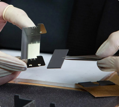
Our flex PCB connectors are designed with both durability and flexibility in mind, making them ideal for applications across industries such as consumer electronics, medical devices, automotive systems, and aerospace. The unique properties of flexible PCBs, including their ability to bend, twist, and conform to different shapes, allow them to fit into tight spaces and complex designs with ease.
0 notes
Text
Charging FPC Connector Compatible For Samsung Galaxy S20 / S20 Plus / S20 Ultra / Note 20 / Note 20 Ultra (54 Pin)
Top quality Charging Port Flex FPC Connector For Samsung Galaxy S20 / S20 Plus / S20 Ultra / Note 20 / Note 20 Ultra (54 Pin) This FPC connector plays an important role when the function of charging and data syncing of charging PCB Board. We recommended for Professional Installation. Samsung Galaxy S20 / S20 Plus / S20 Ultra / Note 20 / Note 20 Ultra Pins: 54 Compatible with G981 / G986 / G988 /…
0 notes
Text
Material Structure and Selection in Rigid-Flex PCBs
Rigid-Flex PCBs combine the stability of rigid boards with the adaptability of flexible circuits. But the key to a successful design lies in material selection and stack-up structure. Choosing the right materials impacts everything from electrical performance and mechanical flexibility to cost and manufacturability.
Below is a breakdown of essential materials used in Rigid-Flex PCBs and considerations for selecting them.
1. Rigid Section Materials
The rigid part of a Rigid-Flex PCB usually serves as the component-mounting area. It uses materials similar to traditional multilayer PCBs.
Common rigid materials:
FR-4 (Standard epoxy-glass laminate) Cost-effective and widely available, suitable for most applications with moderate thermal and electrical requirements.
High-Tg FR-4 Used in designs with higher operating temperatures or lead-free soldering.
Halogen-free FR-4 Chosen for environmental compliance (RoHS, REACH) and flame retardance.
Key properties to consider:
Glass transition temperature (Tg)
Coefficient of thermal expansion (CTE)
Dielectric constant (Dk) and loss tangent (Df)
Thickness tolerance and layer uniformity
2. Flex Section Materials
The flexible part of the PCB must endure bending, folding, and vibration without failure. Flex materials must be thin, strong, and highly resistant to cracking.
Core flex materials:
Polyimide film (PI) The most commonly used dielectric material in flex sections, due to excellent thermal, chemical, and mechanical properties.
Adhesive-based vs adhesiveless polyimide laminates Adhesiveless: Thinner, better dimensional stability, and higher reliability. Adhesive-based: Slightly lower cost, but more prone to delamination under heat or flexing.
Copper types used in flex:
Rolled Annealed (RA) copper High ductility, ideal for repeated bending applications.
Electrodeposited (ED) copper Lower cost, better suited for static flex or one-time folding designs.
3. Coverlay vs Solder Mask
The flexible solder resist layer is typically made from polyimide-based coverlay, not traditional solder mask.
Coverlay: A polyimide film laminated with adhesive, providing insulation and mechanical protection in flex areas.
Flexible solder mask: Can be screen-printed like in rigid boards, but less durable in dynamic bending conditions.
Use coverlay in all bend zones for improved reliability and better protection against cracking or delamination.
4. Stiffener Materials
Stiffeners are added under flex areas to provide mechanical support for connectors or SMT components.
Common stiffener options:
FR-4: Adds thickness and support under connector pads.
Polyimide film: Maintains flexibility while giving local stiffness.
Stainless steel or aluminum: Used when high rigidity is needed in limited space.
Stiffeners are not part of the electrical structure, but must be specified accurately in mechanical drawings.
5. Adhesive Systems
The adhesives used in Rigid-Flex PCBs bond copper to polyimide and help laminate multiple layers together. Adhesive performance directly affects heat resistance, delamination resistance, and bend lifespan.
Adhesives must:
Be compatible with lead-free processing temperatures
Withstand dynamic mechanical stress
Maintain integrity under humidity and thermal cycling
For better thermal and mechanical stability, adhesiveless constructions are preferred in high-reliability or dynamic-flex designs.
6. Material Matching and CTE Compatibility
In Rigid-Flex designs, mismatched materials can lead to mechanical stress, warping, or cracking during lamination or soldering.
Tips for compatibility:
Use materials with similar CTEs across rigid and flex zones
Avoid combining low-Tg and high-Tg materials in one board
Choose laminates tested for multilayer Rigid-Flex constructions
Final Thoughts
The materials chosen for a Rigid-Flex PCB form the backbone of the entire structure — influencing everything from mechanical durability to signal integrity and cost.
A well-designed material stack-up:
Supports complex bending and 3D assembly
Ensures thermal and electrical stability
Reduces risk of failure in critical environments
Enables long-term reliability even under stress
0 notes
Text
Multilayer Flex Circuits: Advanced Solutions for Complex Electronics
Multilayer flex circuits, also known as multilayer flexible printed circuits (FPCs), represent the pinnacle of flexible circuit technology. By combining multiple layers of conductive material in a flexible form, multilayer flex circuits provide an exceptional solution for high-performance, compact, and reliable electronics. These circuits are widely used in various industries where flexibility, high-density interconnects, and space optimization are crucial.
In this blog, we explore what multilayer flex circuits are, their advantages, applications, and why they are becoming increasingly popular in cutting-edge electronics design.
What Are Multilayer Flex Circuits? : MultilayerFlex Circuits
Multilayer flex circuits are flexible printed circuit boards (PCBs) that incorporate more than one layer of conductive traces to create a complex, high-density circuit. These circuits typically consist of multiple layers of flexible base materials, such as polyimide, which are bonded together with inner conductive layers like copper. The conductive traces on each layer are connected using vias (tiny holes that allow electrical connections between the layers), creating a compact and flexible circuit that can handle complex designs.
The key feature of multilayer flex circuits is that they offer multiple layers of electrical interconnections while maintaining the flexibility needed for applications where bending, folding, or compact form factors are essential.
Key Characteristics of Multilayer Flex Circuits : Multilayer Flex Circuits
Multiple Layers of Conductive MaterialMultilayer flex circuits can incorporate anywhere from two to several layers of conductive traces, each carefully designed to carry electrical signals or power. This multi-layer structure allows for high-density interconnections in a compact space.
FlexibilityThe core advantage of flex circuits is their ability to bend, twist, and fold without breaking. This flexibility makes multilayer flex circuits ideal for use in small, intricate, and often dynamic applications where traditional rigid PCBs would not fit.
High-Density Interconnections (HDI)Multilayer flex circuits enable the creation of high-density interconnects, which means more components can be placed on a smaller footprint. This is crucial for modern electronics that require significant functionality in a small, space-constrained design.
Lightweight and CompactMultilayer flex circuits are typically lighter and more compact than their rigid counterparts. They can save space in devices by eliminating the need for connectors, multiple boards, or wiring, leading to more efficient designs.
DurabilityThese circuits are designed to withstand mechanical stress, heat, and environmental factors. The materials used in multilayer flex circuits, such as polyimide, offer excellent thermal and chemical resistance, ensuring long-term performance in demanding conditions.
Advantages of Multilayer Flex Circuits : Multilayer Flex Circuits
Space and Weight SavingsOne of the most significant benefits of multilayer flex circuits is their ability to save both space and weight. These circuits can integrate multiple connections and components into a single compact design, making them perfect for small or portable devices, including wearables, smartphones, and medical devices.
Increased ReliabilityWith fewer connectors and components needed, multilayer flex circuits reduce the chances of connection failures or signal loss, improving the overall reliability of the device. The absence of solder joints and the use of fewer interconnects results in fewer points of failure.
Design FlexibilityThe flexibility of multilayer flex circuits allows for more creative and innovative designs. They can be bent or shaped to fit within unique form factors, such as conforming to curved surfaces or fitting into tight spaces without sacrificing electrical performance.
Improved PerformanceBy using multiple layers to route electrical signals and power, multilayer flex circuits improve signal integrity and reduce the chances of signal interference. Their high-density interconnects also support higher data rates, making them suitable for high-performance applications.
Reduced Assembly ComplexityMultilayer flex circuits reduce the need for separate boards and connectors, streamlining the assembly process and reducing the overall number of parts in a system. This can result in lower overall production costs and faster time-to-market.
Applications of Multilayer Flex Circuits : Multilayer Flex Circuits
Consumer ElectronicsMultilayer flex circuits are commonly found in consumer electronics like smartphones, laptops, tablets, and wearable devices (smartwatches, fitness trackers). Their small size, flexibility, and high-density interconnects make them ideal for devices that require a lot of functionality in a small, compact form factor.
Medical DevicesMedical devices, including diagnostic equipment, monitoring systems, and implantable devices, benefit from multilayer flex circuits' compactness and reliability. These circuits can be designed to fit in limited spaces while still providing the performance needed for sensitive medical applications.
Aerospace and DefenseMultilayer flex circuits are crucial in aerospace and defense systems where high-performance electronics must withstand harsh environmental conditions, such as extreme temperatures, vibrations, and radiation. They are used in satellite systems, avionics, and military communication devices.
AutomotiveThe automotive industry uses multilayer flex circuits in advanced driver-assistance systems (ADAS), infotainment systems, and electronic control units (ECUs). Their ability to perform reliably in high-stress, high-vibration environments makes them suitable for automotive applications.
Industrial EquipmentIn industrial settings, multilayer flex circuits are used in machinery control systems, robotics, and automation. These circuits' flexibility allows them to be used in a variety of form factors, ensuring seamless integration into complex systems.
Challenges of Multilayer Flex Circuits : Multilayer Flex Circuits
Higher Manufacturing Cost
Due to the complexity of manufacturing and the use of multiple layers, multilayer flex circuits can be more expensive to produce than single-layer flexible circuits or traditional rigid PCBs. However, their long-term benefits often justify the higher upfront costs.
Design ComplexityDesigning multilayer flex circuits requires careful planning, as routing the connections through multiple layers without compromising performance can be complex. The design must take into account the bending radius, layer bonding, and other factors to ensure the circuit will function as intended.
Limited Bend RadiusWhile flexible circuits can bend, multilayer designs have certain limitations in terms of how tightly they can be bent. Exceeding the recommended bend radius can lead to cracking or damage to the circuit, so designers must ensure proper design considerations are made.
Thermal ManagementMultilayer flex circuits can generate heat, and effectively managing heat dissipation becomes more challenging as the circuit density increases. Careful material selection and design strategies are needed to ensure that thermal issues do not compromise the circuit’s performance.
Conclusion
Multilayer flex circuits represent an advanced solution for modern electronics design, offering the perfect combination of flexibility, compactness, and high-performance capabilities. These circuits are ideal for applications that require a high-density interconnect, space optimization, and durability in dynamic environments.
As industries continue to push the boundaries of innovation, multilayer flex circuits will play a crucial role in enabling more sophisticated, compact, and reliable electronic devices. Whether it's in consumer electronics, medical equipment, automotive, or aerospace applications, multilayer flex circuits are becoming an essential component in the next generation of electronics.
0 notes
Text
The Role of Flexible PCB Design in Next-Generation Robotics
Robotics and automation are not buzzwords anymore. We all witness the latest flying robots, auto-balancing AGVs, and industrial heavy collaborative robots that are revolutionizing the way we work. But do you know that PCBs are the “brain” of these technology marvels?
With the exponential demand for robotics in every field, the demand for smaller, lighter, more flexible electronic components, especially flex PCBs, is rapidly increasing. According to the International Federation of Robotics, there was a 48% increase in professional service robot sales globally by 2022. In such a scenario, flexible printed circuit boards (PCBs) have become the cornerstone of this transformation. Their special construction and ability are crucial for addressing the design difficulties given by next-generation robotics.
This article will explore how flexible PCB design is transforming robotics and what that implies for PCB manufacture.
Why Robotics Need Flexible PCBs
Unlike conventional rigid PCBs, flexible PCBs are designed to bend and twist, which creates countless opportunities for integrating electronics into the intricate forms and motions needed for robotic applications. For robotics, where designs generally call for flexibility and durability, flex PCBs, which can manage movement and fit into small areas, are perfect.
Key Benefits of Flexible PCB Design for Robotics
Flex PCBs are specially designed to focus on some key benefits that are essential for robotics and complex electronic devices. Some of the noteworthy advantages are:
Adaptability: Flexible PCBs can fit the form of the robotic component, therefore enabling designers to create thinner, lighter systems without compromising performance.
Durability: For robots with moving parts, these boards are perfect since they can absorb stress created during motion and vibration.
Space optimization: By reducing the need for connectors and bulky wiring, flexible PCBs free up valuable space and reduce the weight of the robot.
Enhanced reliability: High-performance robotics depend on fewer sources of failure. Flex PCBs reduce the requirements of connectors and bulky wirings, and therefore, they improve the robot's reliability.
Applications of Flexible PCBs in Robotics
From simple consumer devices to sophisticated industrial machines, flexible PCBs are fast taking the stage in many different robotic applications. Here is where flexible PCB manufacturing is taking the front stage:
Wearable Robots: Wearable robots are used in medical and fitness applications, and they require lightweight, comfortable designs. Flex PCBs make it possible for these devices to bend and contour to the user's body.
Drones and autonomous vehicles: Autonomous cars and drones call for lightweight parts that can withstand stress from continuous motion and fit small areas. Flexible PCBs enable maximum efficiency and help to reduce weight.
Industrial robots: Flexible PCBs can withstand the wear and tear of motion without compromising on performance. Therefore, it becomes highly dependable without sacrificing space for robotics undertaking repetitive tasks.
Important Considerations in Robotics Flexible PCB Design
Flexible PCB design for robotics presents certain difficulties. These are some crucial elements to consider:
Selection of Materials
Flexibility, durability, and heat resistance depend on the selected materials; hence, they are quite important. Because of its heat resistance, flexibility, and durability, polyimide is a common choice for flexible PCB manufacture.
Thickness and Layer Count
The number of layers in a flex PCB might range from one to many. The design requirements for the robot will dictate the optimal balance between physical flexibility and usefulness since adding more layers can limit its adaptability.
Copper Traces and Bend Radius
Careful design of copper traces in a flexible PCB helps to prevent cracks or breakage. Ensuring that traces follow a specific bend radius can help maintain the board's integrity during movement.
Component Placement
During operations, robots experience shocks and vibrations, so it's crucial to strategically place components and reinforce areas prone to bending. This lowers the possibility of component failure in high-stress environments.
Final Thoughts: Embracing Flexible PCBs into Your Robotic Designs
As it offers the adaptability, longevity, and efficiency required for modern, complicated applications, flexible PCB design plays an obvious role in robotics. As a PCB manufacturer, you can broaden the capabilities of robotics by learning about and making use of flex PCBs.
Including flexible PCBs in robotic designs not only creates more space-efficient, robust machines but also helps you to be in front of a market where innovation is vital. Adaptable electronics will surely define the direction of robotics going forward; flexible PCB fabrication has the power to propel these developments ahead.
PCB Power is your one-stop solution, providing premium, durable PCBs to support all technological advancements such as RoboticsLooking for a reliable flex PCB manufacturer for your project? Email us at [email protected] or call us at +1(818) 886 8900. Read More: The Role of Flexible PCB Design in Next-Generation Robotics
0 notes