#mechanical cad engineer
Explore tagged Tumblr posts
Visit Tumblr Blog
Explore Tumblr blogs with no restrictions, modern design and the best experience.
Last Seen Tumblr Blogs


Fun Fact
70% of Tumblr users say the Dashboard is their favorite place to spend time online.
Text

The automotive sector is one of the most dynamic and rapidly evolving industries in the world. It includes everything from the design and manufacturing of vehicles to advanced technologies like electric vehicles (EVs), autonomous driving, and smart mobility solutions. The industry plays a crucial role in global economic growth, employing millions of people and driving technological advancements.
0 notes
Text


#they've got that .DWG in them#she's got that .DWG in her#he's got that .DWG in him#font: monaspace krypton#engineering humor#CAD#AutoCAD#AutoDesk Revit#AutoDesk#Revit#foldmorepaper#wordart#program: xara 3d maker#xara3dmaker#gif#transparent#word art#text gif#engineering#mechanical engineering#MEP#architectural engineering#civil engineering#engineer#DWG#drafting
21 notes
·
View notes
Text

@yellydany’s oc, Danzil!
#myart#digital art#art#its a bit sketchy but it’s for practice so that’s okay#Doubles as a gift too📈#Constantly all the time effortlessly efficient I am#I promise 🙏 I am not lying I guarantee I am extremely organised and put together😁#Just evade everything else I do other than this post and don’t read past the 3rd tag#Because I think it really says something when I go to the tag limit on nearly every one of my posts#I just have things to say I guess#Big time speaker#Unrelated but I’m trying to draw a train and it’s not working out#All those mechanics in the dark. Behind the wheels#Somebody get a flashlight#Also I may start posting photos I take#Because I double down and I am also#get this#A Big time photographer#Or or or#Big time engineer#infested with CAD programs 😕😕😕#Never woodworking though#I show my mistakes but not those ones#Hurrah! No tag cap! Cheer for me
13 notes
·
View notes
Text

Still working even though not making much progress, currently I’m working on things to increase precision in the parts themselves as I haven’t thought of any ways to improve the mechanics.
The main problem I’m having is that small deflections in the part where the leg attaches to the driver results in significant problems in the knee area. I have been able to improve this with precision but I think to make it work well I think I need to redesign something to hold the knee joint parallel
I’m continuing to make small improvements so hopefully I come up with something soon!
2 notes
·
View notes
Text
Capstone #6: Solid
<-<- FIRST || <- PREV || NEXT ->

CAD is nearly done, and the design is 95% there. There's still some improvements to be made. Big 'ol hand to our CAD team especially for bringing this to life. Lets explore under the cut
There's 2 main parts of this thing. The main body has the fans and wheels. The gantry on top does all the doodling. Let's pop the top off.

The cover and walls are purely aesthetic and keeps the dust out. Originally the cover is held on using snap buttons, but that's been changed to the tiniest magnets pocket change can buy. The base plate is made from thin wood, or we've been exploring carbon fiber (but that's proven to be mad expensive for basically no gain. Like 400+$ expensive).
The wheels are servos, the fans sit side by side and run off wall outlet power. (Try making these drone motors that normally run off batteries, and make them run off a wall outlet. Sounds easy right? Good luck. It's been a time doing it. They eat something like 12-16v at 40-60+ amps... *each*). It's got tiny nubs on the bottom to stabilize it, because with only 2 wheels, it's going to want to rock side to side. It'll have some distance sensors on the sides to find where it is on the wall, and an accelerometer to find how it's tilted. I'm personally a little worried the vibrations from the fans will make the accelerometer unreliable, but we'll find out about that later. The whole thing will be controlled by an Arduino Mega.

Smooving over to the gantry, both axis will be on rails purchased from Igus. The rails are made from hard anodized aluminum, while the carriages are made from diecast zinc and some slippery bearing plastic. It's then pulled around by timing belts and steppers. We modified both axis a tad by reducing the rail size to the smallest ones Igus offers, and giving the horizontal axis 2 rails for more stability (The bearing situation on the timing belts were improved too)

The printer head uses an electro-magnet to pull the pen down. There are guide pins with springs to, well, guide and spring return the head. There are also stop screws that set the maximum engagement and disengagement. (The travel distance is kinda exaggerated here tho. The actual travel distance will be as little as possible. Like 3-4mm)
All in all, the bot body is something like 300 x 500mm, 60mm thick (+ 55mm for the fan tails), with a print area of 150 x 150mm. We've tried to cut as much weight as possible, and are looking at about 1.2kg or a little lighter than a small toaster

As a bonus pic, here's an early concept. This one uses a lead screw for the X, and a shaft and timing belt for the Y. If you're wondering what stops the axis from pivoting, it would have been some gibs located behind both axis. Commonly used on dovetails, a gib is when you intentionally design in a large gap between your mating surfaces, and shove a thin plate in there with setscrews to take up the slack. Look at the ways of basically any milling machine or lathe, and chances are you'll see one!
2 notes
·
View notes
Text
when all else fails, close the program and re-fucking-start
#this is about solidworks#solidworks#damn i cant believe theres a tag for that#i have a love-hate relationship with this software#right now im experiencing hate#engineering#mechanical engineering#college#cad software
4 notes
·
View notes
Text
Want to build a 3D CAD viewer in C#?

👨💻 Want to build a 3D CAD viewer in C#? With Eyeshot (devDept), it’s much easier than you think! This guide will take you through each step, from setting up your project to displaying 3D models. You'll learn how to implement essential features such as zoom, rotation, and panning, allowing users to explore designs effortlessly.
By the end of this process, you'll have a functional viewer that you can customize for any project. Perfect for engineers and developers!
👉 Check the full guide here: 🔗 https://blog.prototechsolutions.com/build-a-3d-cad-viewer-in-c-using-eyeshot/
#DotNet#CSharp#Eyeshot#devDept#CAD Development#Software Development#Engineering Software#Mechanical Engineering#3D Programming#CAD Design#CAM Software#CAD Viewer#ProtoTech Solutions
0 notes
Photo

Unlock the future of mechanical design with Onshape: this detailed CAD model of a high-performance bicycle frame highlights the software's advanced 3D modeling capabilities and seamless cloud-based collaboration, setting the standard for the best CAD software in the industry.
0 notes
Text
Once I get my own 3D printer you’ll never see me again ok
0 notes
Text

Top 5 Best CAD Software for Mechanical Design in 2025
Introduction
In the world of mechanical engineering, designing accurate, functional, and reliable components is critical. This is where CAD (Computer-Aided Design) software comes into play. CAD tools help engineers create, modify, analyze, and optimize mechanical designs with precision and efficiency.
With dozens of software options available, selecting the right CAD software can be challenging. Whether you're a student, a beginner, or a professional mechanical designer, this guide highlights the Top 5 Best CAD Software for Mechanical Design in 2024 to help you make the right choice.
1. AutoCAD
Overview:
Developed by Autodesk, AutoCAD has been a staple in the engineering and architecture industries for decades. It is widely used for 2D drafting and 3D modeling.
Key Features:
Precision drawing tools
Extensive library of mechanical components
Easy collaboration and documentation
Widely supported file formats
Best For:
Mechanical engineers and drafters who need detailed 2D/3D design capabilities.
2. SolidWorks
Overview:
SolidWorks, developed by Dassault Systèmes, is a parametric CAD tool that is highly favored for mechanical part and assembly design. It offers powerful simulation tools and an intuitive interface.
Key Features:
3D modeling with real-time simulation
Assembly modeling and motion analysis
Built-in design automation
Excellent for product development and prototyping
Best For:
Mechanical designers working with assemblies, simulations, and custom product development.
3. CATIA
Overview:
CATIA (Computer-Aided Three-dimensional Interactive Application) is another powerful tool from Dassault Systèmes, mainly used in the aerospace and automotive industries for complex product designs.
Key Features:
Advanced surface modeling and multi-disciplinary design
Seamless collaboration between teams
Integration with PLM (Product Lifecycle Management) tools
High-level system engineering support
Best For:
Large-scale industrial mechanical design, especially in high-end industries like aerospace.
4. Creo (formerly Pro/ENGINEER)
Overview:
Creo, developed by PTC, is known for its robust feature set covering everything from conceptual design to product simulation. It supports parametric and direct modeling.
Key Features:
Real-time simulation and analysis
AR (Augmented Reality) design visualization
Detailed sheet metal and plastic part design
Scalability across different stages of design
Best For:
Advanced mechanical engineering applications and enterprise-level product design.
5. Fusion 360
Overview:
Fusion 360 is a cloud-based CAD/CAM/CAE software from Autodesk. It’s beginner-friendly and widely used for product development, 3D printing, and CNC manufacturing.
Key Features:
Unified platform for CAD, CAM, and CAE
Cloud-based collaboration and file access
Free for students, startups, and hobbyists
Integrated simulation and generative design
Best For:
Startups, students, and small teams looking for a versatile and budget-friendly solution.
Conclusion
Choosing the right CAD software depends on your project requirements, industry standards, and level of expertise. Whether you're designing complex machinery or prototyping small components, these tools can transform your ideas into high-precision models.
From AutoCAD’s 2D/3D drafting to Fusion 360’s all-in-one cloud platform, each software brings unique strengths to the table. Mastering any of them can significantly boost your career in mechanical design.
#CAD Software 2025#Best CAD for Mechanical Design#3D CAD Tools#Engineering Design Software#Mechanical Design CAD#Top CAD Software 2025
0 notes
Text
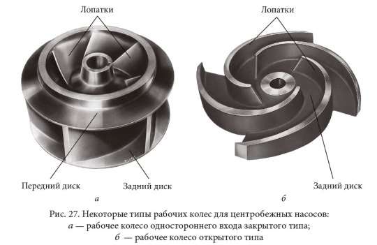
This thing was my first "WHAT THE FUCK IS GOING ON" when I was learning CAD modeling. Now I have nightmares about rotors
1 note
·
View note
Text

Master Multi AutoCAD Skills for 2D & 3D Design Like a Pro
Looking to upskill in CAD design? The Multi AutoCAD course covers 2D drafting, 3D modeling, interior layouts, civil, mechanical, and architectural drawings – all in one complete program. This course is ideal for engineers, architects, and design students who want to gain real-world AutoCAD experience across multiple domains. Learn advanced techniques, industry workflows, and design practices that align with today's project requirements. Whether you're preparing for a career in design or want to boost your professional value, Multi AutoCAD training offers the flexibility and depth you need.
Start your journey toward CAD mastery today with the right guidance and tools.
Visit Attitude Academy📚
📍 Visit Us: Yamuna Vihar | Uttam Nagar
📞 Call: +91 9654382235
🌐 Website: www.attitudetallyacademy.com
📩 Email: [email protected]
📸 Follow us on: attitudeacademy4u
#Multi AutoCAD Course#AutoCAD 2D and 3D Training#AutoCAD for Civil Engineering#AutoCAD for Mechanical Design#AutoCAD Architecture Course#Learn AutoCAD Online#Advanced AutoCAD Training#2D Drafting and 3D Modeling Course#CAD Design Course#AutoCAD Certification Course#Best AutoCAD Course#AutoCAD Training Institute#AutoCAD Classes for Beginners#AutoCAD Interior Design Course#Professional AutoCAD Program
0 notes
Text
#mechanical engineering#engineering drawings#design standards#technical drafting#manufacturing blueprints#CAD design
0 notes
Text
This last modification has been the most difficult so far, mainly because I needed three layers rotating in different ways without interference, but I finally have a configuration i think would work well; though it still needs minor adjustments.
I have also used up the initial board I got for this project and I'm ordering much better material this time, though its going to take a week to arrive, I'd likely need it anyways as a still need to get the car attachment mechanism on each side as well as remaking everything to be ready for the cutter. I have a lot more work to do before this next step is out but i have time before school and work starts up again in a couple weeks so i think ill have this edition done soon!
2 notes
·
View notes
Text
Drive Agricultural Engineering Innovation: Mechanical Engineering Lecturer/Professor Opportunity at NUST! - March 2025
The National University of Science and Technology (NUST) is seeking a dynamic and experienced academic to join their Department of Agricultural Engineering as a Lecturer/Senior Lecturer/Associate Professor specializing in Mechanical Engineering! If you’re passionate about advancing agricultural engineering through mechanical design and manufacturing, this is an excellent opportunity. About the…

View On WordPress
#Agricultural Engineering Jobs#Bulawayo Jobs#CAD CAM#education#Engineering#Engineering Drawing#Hot Zimbabwe Jobs#Industrial Engineering Jobs#Job Opportunity#Lecturer Jobs#Manufacturing Engineering Jobs#Mechanical Engineering Jobs#news#NUST Jobs#Professor Jobs#Research Jobs#Teaching Jobs#technology#University Jobs#Zimbabwe Jobs
1 note
·
View note
Text
Top Product Design Services 3D CAD Modeling and Prototyping Solutions From concept to prototype, Shalin Designs offers excellent product design services, 3D CAD modeling, and design for manufacturing to bring your ideas to life.
#Product design services#3D CAD modeling services#Prototype development services#Industrial product design#Custom product design solutions#Mechanical product design#Engineering design services#Product prototyping service#Manufacturing design solutions#CAD product design
0 notes