#tymkrs
Explore tagged Tumblr posts
Visit Tumblr Blog
Explore Tumblr blogs with no restrictions, modern design and the best experience.
Last Seen Tumblr Blogs


Fun Fact
Total funding amounts to $125.3M.
Text
Honoring the ’80s, Def Con’s badge is also a text adventure

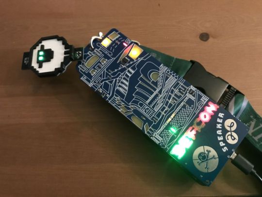
Enlarge / My DEF CON badge, complete with Wall of Sheep add-on from the DC801 crew, built by @kL34N and @SirGed. My puzzle quest is far from complete—it may require reprogramming and flipping a component. (credit: Sean Gallagher)
Nearly 30,000 people came to Las Vegas last week for the 26th edition of DEF CON, the iconic security conference. And no small amount of the mental energy of that vast crowd was spent on one particular thing: the conference badge.
This year’s badges, designed by Tymkrs, were elevated works of printed circuit board art with a collection of LED-lit features, including red and green human figures and a color-shifting DEF CON logo. But it quickly becomes apparent that there was a lot more going on here than just blinking lights.
DEF CON alternates year to year between electronic, hackable badges and non-electronic ones; last year’s badges were a throwback design intended to celebrate the conference’s 25th anniversary. But every year, the badges include some sort of clue to a cryptographic challenge—three years ago, the badge was an actual vinyl record that required attendees to find a turntable to hear the puzzle clue.
Read 7 remaining paragraphs | Comments
Honoring the ’80s, Def Con’s badge is also a text adventure syndicated from https://medium.com/@eooke
Honoring the ’80s, Def Con’s badge is also a text adventure syndicated from https://barbarawalston.wordpress.com/
0 notes
Text
Honoring the ’80s, Def Con’s badge is also a text adventure
Enlarge / My DEF CON badge, complete with Wall of Sheep add-on from the DC801 crew, built by @kL34N and @SirGed. My puzzle quest is far from complete—it may require reprogramming and flipping a component. (credit: Sean Gallagher)
Nearly 30,000 people came to Las Vegas last week for the 26th edition of DEF CON, the iconic security conference. And no small amount of the mental energy of that vast crowd was spent on one particular thing: the conference badge.
This year's badges, designed by Tymkrs, were elevated works of printed circuit board art with a collection of LED-lit features, including red and green human figures and a color-shifting DEF CON logo. But it quickly becomes apparent that there was a lot more going on here than just blinking lights.
DEF CON alternates year to year between electronic, hackable badges and non-electronic ones; last year's badges were a throwback design intended to celebrate the conference's 25th anniversary. But every year, the badges include some sort of clue to a cryptographic challenge—three years ago, the badge was an actual vinyl record that required attendees to find a turntable to hear the puzzle clue.
Read 7 remaining paragraphs | Comments
Honoring the ’80s, Def Con’s badge is also a text adventure published first on https://medium.com/@CPUCHamp
0 notes
Video
youtube
Tymkrs Protosynth https://youtu.be/Ma1m228P9kc
0 notes
Text
The Cubic Cyphercon Badge
Last week in Milwaukee was Cyphercon, Wisconsin’s premier hacker conference. You can’t do a hacker con without either an electronic conference badge or a 45 hanging off a lanyard, and the Cyphercon 2017 badge doesn’t disappoint. It’s an electronic cube, lovingly designed by the folks at tymkrs. It’s also a puzzle box with security holes and wireless communications. It’s a mesh network of badges, and one of the best conference badges we’ve ever seen. The most obvious feature of the Cyphercon 2.0 badge is the extra dimension. From the outset, the design of this badge was a 3-dimensional cube, constructed …read more http://pje.fyi/NsqFK0
0 notes
Video
youtube
Heart Me - MicroMedic 2013 (by whisk0r)
Cranquistador tymkrs, a nurse/engineer, has created a tiny anatomically-correct (down to level of the Purkinje fibers!) heart-shaped LED gizmo which displays 17 different heart rhythms -- and lets you FEEL them too.
Honestly, if this came with a little remote control shaped like a defibrillator paddle, I'd have to get one for Mrs. Cranquis' next Valentine's Day gift.
Check it out!
EDIT: Here's a 2nd video, which shows the LEDs in better lighting.
123 notes
·
View notes
Text
Working on the LED Heart: 2AVB Type 1 & 2, 3AVB

So assuming normal sinus rhythm is the following:
P Wave: 80ms
PR Segment: 50-120ms - I'll use 100ms for a PR Interval of 180ms
QRS: 80-120ms - I'll use 100ms
RR Interval: 0.6-1.2s but taking away the 280ms from the PQRS, that leaves us with 720ms assuming a RR of 1second.
Second Degree Atrioventricular Block Type 1 Code:

So with 2AVB Type 1, what happens is the PR intervals increase, increase, increase, then drop a QRS beat.
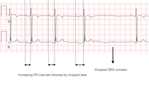
This code may have to change because I adjusted the T-P intervals to maintain the same time per beat - but according to this ECG, each beat goes progressively longer - so actually it'd be easier for me to just have left the T-P intervals the same.
Second Degree Atrioventricular Block Type 2 Code:

So this one essentially is where there's no lengthening of the PR interval, there are just dropped QRS complexes.

This is pretty dangerous because you never know when there'll be a complete block between atrium and ventricles. That these look to be 3:1 or 6:1 conduction doesn't mean that it couldn't become 0 conduction.
Third Degree Atrioventricular Block Code:

So with this, I spawned off two cogs - and this is accurate in how Third Degree AVB functions. The atrium go at their own rate, the ventricles go at their own rate. There is zero communication between the two. I had the rate of the atrium go at 60bpm. And the ventricles were somewhere like 37bpm or so because the intrinsic rates of the ventricles are 20-40. This of course is dangerous because you don't have efficient filling of the ventricles from the atrium pumping their blood through. And because you never know when the ventricles will start fibrillating from lack of cohesiveness.
Last few rhythms: Junctional Rhythm and Sinus Rhythm with Bundle Branch Block!
@atdiy/@tymkrs
#LED Heart#tymkrs#parallax#propeller#spin#second degree block type 1#second degree block type 2#cardiac#third degree block#electronics
78 notes
·
View notes
Photo

Just in time for my 9,000-follower mark: It's DR. CRANQUIS' CHRISTMAS SURPRISE: Over an hour of audio-only interview of yours truly (with voice disguised a bit) containing:
on-the-spot answers to reader questions
discussions about telemedicine and whether doctors will be the first to go in a zombie apocalypse
a link to Dr. Cranquis' personal never-before-shared (because it's downright bizarre) other Tumblr blog.
Bonus: I sing a song that I wrote for my other blog, near the end of the interview.
Consider this my early Christmas present to all of my Constant Readers. Enjoy!
(and a HUGE thank-you to Addie "tymkrs" for offering me this interview opportunity -- what a fun and flattering experience!)
#announcement#cranquis christmas surprise#fan art#zombies#tymkrs#zombie-pocalypse#compliments#popular#audio#zombietech.tv
116 notes
·
View notes
Text
First Spin!
So if you've followed along with some of our more recent videos, posts, and such - you'll know that I've started programming some of my first projects on the Parallax Propeller platform.
Welp, to document this process of my incessant Q/A sessions, we've decided to record it for you in our new Parallax-sponsored podcast called First Spin. You can find it on firstspin.tv and includes myself, @whixr, and @RoyEltham.
It'll be 30 minutes of my asking questions from a complete n00b perspective and Whisker and Roy trying to explain it to me so that my eyes don't glaze over. It'll be my learning about the propeller chip as well as how to program in Spin, its programming language.
We'll be releasing it on Tuesdays and if you have any questions about what we're going over - let us know!
@atdiy/@tymkrs
54 notes
·
View notes
Text
Two Stage FM Transmitter Bug - Preamplifier
So it's been a while but I thought I'd analyze another schematic similar to the last transmitter bug. @JohnS_AZ also sent this one to us and it is a two stage FM transmitter bug - supposedly more powerful and capable. It works with a 9v battery and claims to have a range of up to 1km in the open.
So as in the first transmitter we looked at, the microphone from where our mic level input comes from is an electret microphone. The preamplifier circuit is quite similar to the one we've seen before:

The main differences you'll note are in the values of the resistor from the power rail to the mic and from the power rail to the collector electrode of the transistor. I'm not sure of the significance, but perhaps because FM transmitter 2 has three amplification stages as opposed to two, the electret microphone is provided with less power than FM transmitter 1.
You'll note that the output of the transistor preamplifier stage still goes through a 100nf capacitor as before. The one new thing we see is a 100nf coupling capacitor connecting the power rail to ground. This must be some sort of dc filtering capacitor that helps to get rid of any additional noise.
And to reiterate some of what we learned from analyzing the last preamplifier circuit, the initial 22nf capacitor filters out DC currents and allows AC currents (our audio signal) through.
Then, the 22k resistor and 1M resistor do what is known as biasing the base electrode of the transistor. Remember that it is both the signal and strength of the signal going into the base electrode that determines to what degree the transistor amplifies that secondary current that becomes the output of that stage.

This handy gif was what helped me realize that the two currents were separate but that the one going to the base electrode determined/allowed the amplified current to proceed.
Next up! The adjustable/tunable tank circuit and amplification 1 stage!
@atdiy/@tymkrs
#two stage fm transmitter bug#preamplifier circuit#fm transmitter#tymkrs#electronics#electret microphones#DIY Kit 32#DIY#transistor biasing#transistor#base electrode#collector electrode#emitter electrode
52 notes
·
View notes
Text
Ham Radio: Electrical Safety!
Last chapter before the glossary!! I see light at the end of this wondrous tunnel :). So respect electricity. AC and DC current can cause shocks and burns if you're not careful and depending on the voltages, can range from insignificant to deadly.
Voltage is what causes the charge to flow but doesn't shock all by itself. Essentially, as the voltage applied across your body varies, so does current. This is because different parts of your body conduct different. The interior of your body conducts quite well as it is mostly salty water.
Current Reaction
< 1milliamp Generally not perceptible
1 Faint tingle
5 Slight shock felt, not painful but disturbing. Average
person can let go but strong involuntary reactions can
lead to other injuries.
6-25 (women) Painful shock, loss of muscular control; the freezing
9-30 (men) current or can't let go range.
50-150 Extreme pain, respiratory arrest, severe muscular
contractions. Death is possible.
1000-4300 Heart stops. Muscular contraction and nerve damage
occur; death likely.
10000 Cardiac arrest, severe burns, death probable.
The most dangerous currents are those that travel through the heart such as hand to hand or hand to foot. Electrical currents of 100mA or more can disrupt normal heart rhythm. Depending on the resistance of the path taken by the current, voltages as low as 30 volts can cause enough current flow to be dangerous.
And burns caused by dc current or low frequency ac current are a result of resistance to current in the skin, either through it or along it. The current --> heat --> burn.
These are obviously preventable if there's no way for you to come in contact with an energized conductor. Remove, insulate, secure loose wires and cables before testing or repairing equipment. Never assume equipment is off or de-energized before beginning your work. Check with a meter or tester first. And if you do need to work on equipment with the power on - the following steps are the manual's suggestions:
Keep one hand in your pocket while probing or testing energized equipment and wear insulating shoes. This gives current nowhere to flow in or along your body.
It's easy to have bad habits while working with low voltage or battery powered equipment. Be extra careful when changing to work around higher voltages.
Never bypass a safety interlock during testing unless specifically instructed to do so. These remove power when access panels, covers, or doors are opened to hazardous areas in equipment.
Capacitors can store charge (as we know) after a charging circuit is turned off, presenting a hazardous voltage for a long time. Make sure all high-voltage capacitors are discharged by testing them with a meter or use a grounding stick to shunt their charge to ground.
Storage batteries release a lot of energy if shorted. Keep metal objects such as tools and sheet metal clear of battery terminals and avoid working on equipment with the battery connected.
Remove unnecessary jewelry from your hands. Rings can absorb RF energy and get hot in a strong RF field.
Avoid working along around energized equipment and remember that electricity moves a lot faster than you can.
What do you do? Turn the power off. Install a master ON/OFF switch for AC power to your station and work bench. Learn how to turn it off at the master switch and circuit-breaker box. Learning CPR is probably a good idea too.
@atdiy/@tymkrs
42 notes
·
View notes
Text
Ham Radio: Interference!
I know in football games they call interference, but I don't know what that means. So. Ham Radio instead! Interference is caused by noise and signals. Noise interference is caused by natural sources such as thunderstorms, signals unintentionally radiated by appliances, industrial equipment, and computer equipment.

Interference from nearby signals (QRM) is part of the price of frequency flexibility. If hams operated on assigned and evenly spaced channels, there would be much less interference. They would also be overloaded quite often! But, most interference is manageable.
Common sense and courtesy - No one owns a frequency
Good filters to reject interference
Be aware of other activities such as special events, DXpeditions, and contests
Harmful Interference
If a transmission seriously degrades, obstructs, or repeatedly interrupts the communications of a regulated service, that's considered harmful interference. Each ham should try to minimize the possibility of causing this. Reports of interference such as transmitting off-frequency or generating spurious signals (splatter and buckshot) should be checked out. Remember, when testing/tuning a transmitter, keep test transmissions short.
Sometimes, propagation on a band can change due to ionospheric or atmospheric conditions. A signal that wasn't there a few minutes ago may suddenly become strong enough to disrupt your contact. Changing antenna direction can allow a previously rejected signal to be heard, etc.

The distortion here is most likely caused by accidental interference from ionospheric/atmospheric conditions.
If you are the one dealing with interference, try changing your frequency or changing antenna direction. And if you're the one causing it, apologize, identify and take the needed steps to reduce interference. This could require you to change frequency, reduce power, or move your antenna.
Willful Interference
Simply put, intentionally creating harmful interference is called willful interference and is never allowed. The interference doesn't have to be aimed at one specific contact or group. Anytime communications are deliberately disrupted, that's willful interference. For example, intentionally transmitting spurious signals by overmodulating is willful interference. Common sense and maturity folks.
@atdiy/@tymkrs
#interference#QRM#harmful interference#willful interference#tymkrs#ham radio#ham radio license manual
39 notes
·
View notes
Text
Beta? Hfe? Gain? 2N3904s! I think its transistor theory...
So a bunch of the folks were talking about engineering and electronics and the like in our irc room and I got to talking about how engineers love smashing a whole bunch of letters and numbers together to make chip names sound ridiculous. So I asked folks what their favorite transistor was for audio applications and instead of getting 10 different kinds, a few of them agreed on the 2N3904 (spoilsports :p).
Anyway so somehow they got to explaining how to find the DC current gain of a transistor based on its datasheet and such:
Explanation 1:

Per @mgburr and Lancelot: A 2N3904 transistor's beta max value is 150 and min value is 100. When figuring out DC current gain, the beta value is part of the formula. In the sheet above, it is also known as as hFE. (hFE = beta = gain for easier understanding)
So if you need to build an amplifier with a gain of 300, you set up 3 transistor stages. A good rule of thumb is to build it using the minimum beta value instead of the max:
[100] + [100] + [100] = 300...So even if it's at its minimum, it still has enough gain [150] + [150] + [150] = 450...If all of the transistors were at their max, gain = 450
If you based the gain off of the maximum beta value instead of minimum:
[150] + [150] = 300.... This is possible if it works at its maximum gain BUT [100] + [100] = 200.... This wouldn't give you enough gain!
Now hFE and beta cannot be greater in value than allowed by the gain. Otherwise you get noise caused by saturation and clipping of the signal

If we look further into this, beta/hfe/gain = the ratio of the current going through the collector/the current through the base.
Explanation 2:

Per @brainwagon: Transistor Man looks at the current going from the base to the emitter. He then adjusts the collector/emitter current to be hFe * Ib.
hFE is found on the datasheet (also known as beta/gain) as highlighted in the above datasheet.
Ib is the current at the base.
These are 2 ways to prove that hFE=Gain
Our players are:
Current at the base = Ib
Current at the collector = Ic (or hFe*Ib)
Gain = Gain
First explanation from @mgburr and Lance: Beta/hFE/Gain = the ratio of the current going through the collector/the current through the base
Gain = Ic/Ib
Gain = (hFe*Ib)/Ib
Gain = hFe
Second explanation from @brainwagon: Collector/Emitter current = hFe * Ib
Ic = hFe*Ib
hFe = Ic/Ib
hFe = (hFe*Ib)/Ib
hFe = hFe = Gain
Whew!
@atdiy/@tymkrs
37 notes
·
View notes
Text
Working on the LED Heart: Vfib, VTach, 1AVB
So assuming normal sinus rhythm is the following:
P Wave: 80ms
PR Segment: 50-120ms - I'll use 100ms for a PR Interval of 180ms
QRS: 80-120ms - I'll use 100ms
RR Interval: 0.6-1.2s but taking away the 280ms from the PQRS, that leaves us with 720ms assuming a RR of 1second.
Ventricular fibrillation code:

So Vfib is where all hell breaks loose and there are electrical impulses coming from everywhere in the ventricles. I included the atrium here (labelled Pub PR) but on the rhythm itself, you really don't see anything but ventricular electrical patterns. I did the same thing here as I did for atrial fibrillation, just made it so that the ventricles looked like paparazzi too!
Ventricular tachycardia code:

So I pretty much just made this ventricular activity. Calculated that I wanted the bpm to be more than 150. And the waveform for vtach has a greater "QRS" (if it can be called that), by nearly double if not triple that of normal sized QRSes.
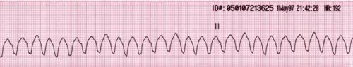
I don't like seeing this and kinda panic when I see this on a patient's rhythm strip.
Sinus Rhythm with 1st degree atrioventricular block (1AVB) Code:

So the main difference here is that instead of the PR segment being only 100ms, giving us a total PR interval (in Normal Sinus Rhythm) of 180ms - in SR1AVB, the PR interval is greater than 200ms. So I made it 230ms. Easy enough! And physiologically, this represents a delayed conduction between the sinoatrial node and the atrioventricular node. It just takes longer for electricity to get from one place to another for some reason (maybe scar tissue).
Next rhythms!: Second Degree AV Block Type 1, Second Degree AV Block Type 2, Third Degree AV Block
@atdiy/@tymkrs
#LED Heart#tymkrs#ventricular fibrillation#ventricular tachycardia#SR 1AVB#First degree block#cardiac#electronics#parallax#propeller#spin
36 notes
·
View notes
Text
Free Indie Game: Quench v0.1.0a
Here is a link to an early alpha test for a simple game we built in a few hours last night. Let us know what you think, and any additions you would like to see. We will be posting several of these beginnings. Your feedback will determine which projects get the most attention, so vote with your voice!
http://treehouse.tymkrs.com/?p=13

@tymkrs
33 notes
·
View notes
Text
Adding the lub-dub into the heartbeat
So the lub-dubs of the heartbeat represent the different pairs of valves closing. If all is working correctly, the atrioventricular valves close at the same time and the semilunar valves close at the same time.

Some notes:
The atrioventricular valves are between the atrium and ventricles. Those connecting the right atrium to the right ventricle are known as the tricuspid valves (tri = right is how I remember it). Those connecting the left atrium to the left ventricle are known as the bicuspid valves.
The semilunar valves are between the ventricles and their destination. Those connecting the right ventricle to the lungs are the pulmonary semilunar valves. Those connecting the left ventricle to the aorta/body are the aortic semilunar valves.
Anyway, so it's "easier" but highly inaccurate to make the lub sound at the same time as the conduction LEDs for the sinoatrial node. This is because the LUB sound actually represents the atrioventricular valves closing.
It's also easier but inaccurate to make the dub sound at the same time as the conduction leds for the atrioventricular node. This is because the DUB sound actually represents the semilunar valves closing.
So for our purposes:

What I've done is put the lub before the QRS, though technically it should be in the middle of it - on its tailend. This actually may be a change I end up doing so no one gets all twitterpated :p
And the dub is placed about 1/3 between the end of the QRS complex and the start of the P of the next wave.

@atdiy/@tymkrs
31 notes
·
View notes
Text
10.25 Ham Lesson o' de day
Capacitors store electrical energy by way of capacitance and is measured in farads - The Farad is the amount of charge capacity that a capacitor can hold. Another way I understood it was that it's the amount of current that it takes to increase voltage within the capacitor by 1volt/second. IE how much current has to pass into the capacitor before the rate of voltage increase = 1 volt/second.
Capacitor Part 1:
@whixr mentioned to me that capacitors are often used to allow AC current but not DC current, and so are known as DC blockers. So another metaphor that he's come up with is the following. Capacitance is like a rubber membrane in a barrel (brown line). Pipes are attached to each end of the barrel and a pump connects those pipes. You can only pump water in one direction so much, then the rubber wall will not stretch anymore (stretching possible according to dotted black lines). Picture:

With DC current, that's like pumping water from only the left to the right side (for instance). The water can only go against the rubber membrane so much, before it stops. If however, you have AC current, it's like the pump pumping water from the left, then the pump pumping water from the right. And the water ends up going back and forth. So that anything in between the pump (power source) and barrel (capacitor) can take advantage of that current. So too capacitors do not allow DC current through and only allow AC current to work upon it.
Capacitor Part 2:
This is of my own making from studying capacitors and from what Whisker's told me about capacitors. Essentially a capacitor's like a cul-de-sac, and kids running into the cul-de-sac is like electrons going into one side of the barrel or electrode. They can't go past the cul-de-sac (re: DC current). The only way is to go back the way they came in (re: AC current).
Capacitor Part 3:
So we have a sandwich: two conducting surfaces called electrodes and between these two electrodes, an insulating dielectric (wood/rubber/air). Remember, conductors allow current to flow easily and insulators do not.

This is when no power is running through yet - when both electrodes have the same number of electrons as the other, and therefore no voltage/electric potential has been induced. (Our dielectric is Gandalf)

And I've gone and gotten the battery on and as always, the current will go towards the positive electrode. Current will go in the only direction it can towards the negative electrode of this capacitor.

Well now that you've gotten all of the electrons on one side of the equation, there's this electric field that's been created, and it's got a huge amount of energy potential behind it. I've gone ahead and taken the battery away.

And when you end up putting both ends of the capacitor on the same conductor, you get a huge rush of electrons rushing back to balance things out = pow! bam! crackle!
Capacitor Part 4:
When a capacitor is connected to a circuit, as current flows into it, it develops an electrical potential (seen above) - this is known as voltage though measured in farads (amount of current to increase the voltage in the capacitor by 1volt/second). Remember that the capacitor always wants to "reequilibrate" or "leak" the current it's been given back into the circuit. That's why capacitors are known as voltage smoothers. Example:

Alright. So we've got a power source that's not very reliable - sometimes it gives out a certain amount of power, and when the weather's bad, it gives out another amount of power. All within a certain range, but not precise all of the time. Everything's connected to ground. And we're trying to light a light bulb. So when the power source is pushing forth too much power, it gets sucked up by the capacitor and the capacitor's "rubber membrane" absorbs that extra energy. However, should the voltage falter from the power source, the capacitor then takes up the slack and releases its energy into the circuit. This allows "voltage smoothing" to occur, and the light bulb would never know the difference!

These are the more common types of capacitors as well as different specs for each. (http://i.cmpnet.com/planetanalog/2007/06/C0201-Table2.gif)
Next article - how to read capacitors!
@atdiy/@tymkrs
#How capacitors work#ham radio license manual#ham radio#tymkrs#capacitance#electrodes#dielectric#farads
31 notes
·
View notes