
We produce creative, educational programming for the geek and diyer. Follow along as we video, photo, tweet and blog all of our crazy diy projects. Electronics, programming, avs, building musical instruments, and what ever else we get interested in. video: tymkrs.com tweets: twitter.com/tymkrs bio: about.me/tymkrs photography: flickr.com/people/tymkrs
Don't wanna be here? Send us removal request.
Statistics
We looked inside some of the posts by tymkrs and here's what we found interesting.
Average Info
Notes Per Post
247K
Likes Per Post
106K
Reblog Per Post
141K
Reply Per Post
5
Time Between Posts
1 month
Number of Posts By Type
Text
14
Photo
1
Audio
1
Note
1
Last Seen Tumblr Blogs


Fun Fact
130K people were victims of a chain letter scam that affected Tumblr in May 2011.
Text
A little less than a year...
...since I stopped updating this religiously, and in that time, we have done quite a few projects! So here is the quasi semi annual update, with hopefully ambitious plans to start blogging again!
Project 1: The time machine!
Probably one of the most significant projects we tackled was changing our house’s phone lines to an internal paging system. This required tracking down all of the different pairs of wires involved in the phone system and seeing how they connected to each other. The following are some of the instructables that came out of that.
http://www.instructables.com/id/Cheap-and-Easy-Guide-to-Building-a-Private-Telepho/
http://www.instructables.com/id/Retrofit-a-PBX-to-Existing-Phone-Lines/
The reason we wanted to do this, besides being able to call each other from any floor of the house, was to work on our “Time Machine” - a system that could get onto the internet but using mostly old school technology.
As seen here: http://www.instructables.com/id/Telecom-Time-Machine/ and it involved the following pieces:
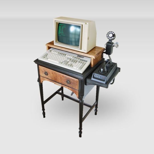
Antique Telephone (G type handset)
300 Baud Acoustic Coupler Modem
DTMF Tone Generator
Private Branch Exchange
Green Phosphor Cathode Ray Tube Monitor
Model M (buckling-spring, clicky) Keyboard
AT to PS2 Keyboard Adapter
PS2 to USB Keyboard Converter
External USB Fax Modem
Raspberry Pi Dial Up Server
Raspberry Pi Dumb Terminal
Seamstress Computer Desk
Project 2: House renovations!
After taking apart the phone system, we wanted to update the upper floor of our house with bamboo floors instead of the old carpet and linoleum. Here is the during:
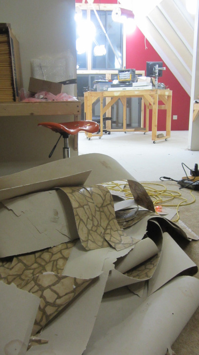
And here is the after (but still before cleaning things up):
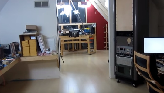
Things have since been cleaned up quite a bit, which leads us to our next project of the year!
Project 3: Cyphercon 2016 Badges
@Goetzman brought us onto the Cyphercon team to make their badges and it was a pretty fun experience, and definitely one where we learned a lot more about the manufacturing process:
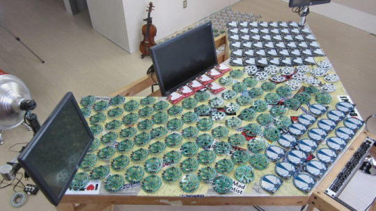
275 of them were hand soldered! It was pretty much nonstop solder pasting for me. Each board was then individually reflowed and tested. And finally switches were soldered on. When I get more close up pictures, I’ll be sure to show you all.
The green ones are those who paid for the Friday portion of the conference. The white ones are the normal con goers. The blue was the speakers, black were the vip, and the red were the life-timers. There’s more information on them on http://hackthebadge.com/
And if you’d like to continue checking our projects, I created a reddit that I treat like our forums. Our previous forums decided to get too much bot traffic and that didn’t make our server provider happy :p Woops.
https://www.reddit.com/r/tymkrs
If you would like to join and see what all is going on!
8 notes
·
View notes
Text
USB PIDs for Open Source USB Projects
At some point in the past, I wrote a blog post about USB PIDs/VIDs and Hackaday recently released a post about a company that was willing to give out PIDs to qualified open source USB projects. Now I don’t think about this everyday, so I was a bit rusty and asked why this was necessary. The following is a summary of what I was taught!
It seems that if you use a USB to serial chip, such as one of FTDI’s many offerings, you can use their PID/VID. The PID is what allows the OS to figure out what drivers to load. Since all FT232x (for instance) have the same driver requirements, people just usually use FTDI’s VID/PID. Ie, it’s only relevant for drivers for the USB to 232 chip.
FTDI has drivers for various other variants of theirs, but in each case their chip is a single-function device, so it’s easier to write generic drivers. But if you’re writing something based on an ATMega32U4, for instance, you’ll need your own PID, since it could do anything.
IE. The ATMega32U4 can be used as an USB to serial chip, as well as anything else you’re able to make it do. So using the ATMega32U4 decreases the number of parts for the board since you don’t need to include a dedicated USB to Serial chip. And of course the MCU of your choice can do anything else - you can make an HID device, or any other number of kinds of devices.
Anyway! So that’s why you might want your own PID - if you’re getting rid of the specific USB to serial chip on your board, and rolling that functionality into a chip that’s doing something else.
For more information on how to get one: http://hackaday.com/2015/04/03/usb-pids-for-all/ and http://hackaday.com/2015/04/03/usb-pids-for-all/
@atdiy/@tymkrs
5 notes
·
View notes


Audio
Listen/purchase: A Bonny Caper by whixr For as long as I’ve known Whisker, he’s been into chiptunes. It only makes sense therefore that given half a chance, he would make his own chiptunes. And so he has! We are so proud to present Whisker’s debut album “A Bonny Caper” - composed, programmed, and arranged by Whisker using the simple but effective technology behind a Gameboy DMG! Please take a listen, retweet, share, let others know who enjoy chiptunes, and let us know what you think!
1 note
·
View note
Text
If you’re interested...
in asking questions or contacting us with cool ideas - please feel free to join our chat room @ http://tymkrs.com/chat. Unfortunately I’m not in the habit of checking tumblr messages and I’m afraid I’ve let some long time readers wait a VERY long time for a response! Apologies for that!
So if you’re an electronics fan or have some question on a project, you’re welcome to join our global hackerspace of engineer miscreants :D
@atdiy
2 notes
·
View notes
Text
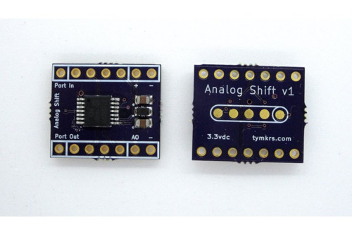
Lots of registers shifting...
...to make audio synth-y goodness!
Tymkrs Analog Shift Kit: This is pretty neat, it is a PIC which acts like a DAC and as a shift register. It allows you to convert a 7-bit digital value into an analog value between 0 to 3.3V, and allows the serial data to pass through (if desired) to another module. (https://www.tindie.com/products/tymkrs/tymkrs-analog-shift-kit/)
Video: https://www.youtube.com/watch?v=2F9Y_RywjzI
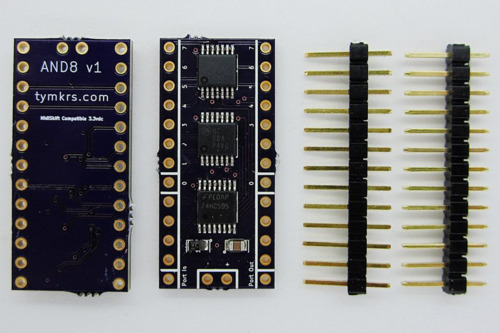
Tymkrs AND8 Module: This is a module with 8 AND gates where one side of each gate is controlled by the output of a 74hc595 shift register and the other side of each gate is controlled by the input of 8 signals of your choice. (https://www.tindie.com/products/tymkrs/tymkrs-and8-module/)
Video: https://www.youtube.com/watch?v=kuG__jFfwHQ
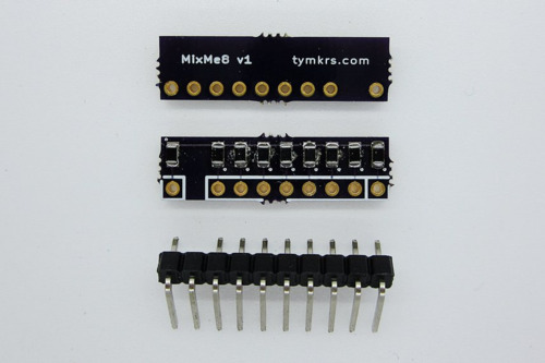
Tymkrs MixMe 8: This module is a passive summing mixer for super cheap! It takes 8 signals in and gives you one signal out. We've used it with audio for great success! (https://www.tindie.com/products/tymkrs/tymkrs-mixme8-module/)
Video: https://www.youtube.com/watch?v=kuG__jFfwHQ
@atdiy/@tymkrs
2 notes
·
View notes
Text
In our continued quest...
...for exposing the world to useful gadgets!
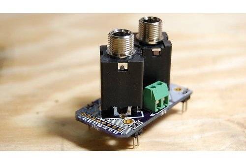
Tymkrs Jack Me Kit: This is a kit which breaks out 2 quarter-inch jacks. The jacks can be connected to each other, or they could be used to send audio signals through your breadboardable circuit - and vice versa! (https://www.tindie.com/products/tymkrs/tymkrs-jack-me/)
Video: https://www.youtube.com/watch?v=rATTrNapPw4
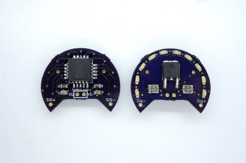
Tymkrs VU Meter Kit: This is an audio visualiser known as a VU meter! (volume unit meter) It's super cute and breadboard friendly! (https://www.tindie.com/products/tymkrs/vu-meter-kit/)
Video: https://www.youtube.com/watch?v=ahtNntQUEfg
5 notes
·
View notes
Text
It's been a while!
...since we posted a new blog, but we have been extremely busy! We've been focusing on creating more music-related modules since the holidays last year and I'd love for you guys to take a look and ask questions. I'm in charge of documentation and while I know some of the things I should include, by no means do I know all!
Just to show you guys what we've been up to:
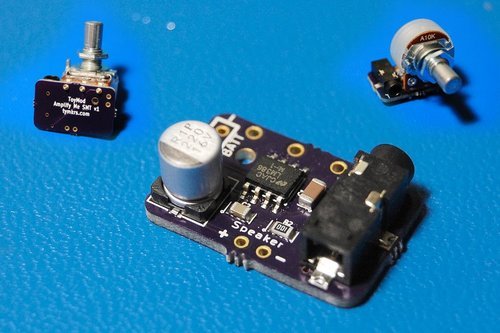
SMT LM386 Amplify Me Kit - this is an LM386 based amplifier which takes up a very small footprint and has the same functionality as our throughhole Amplify Me Kit. (https://www.tindie.com/products/tymkrs/tymkrs-smt-amplify-me-lm386-kit/)
Video: https://www.youtube.com/watch?v=vWWHLcbNO0k
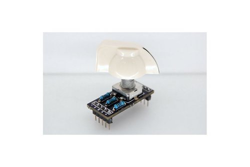
Turn Me Kit: This is a quadrature encoder kit which also takes up a very small footprint and is breadboard friendly. (https://www.tindie.com/products/tymkrs/tymkrs-turn-me-v1-rotary-encoder-kit/)
Video: https://www.youtube.com/watch?v=5soQlJ73UNU
#smt lm386#lm386#turn me#amplify me#tymkrs#smt amplify me#quadrature encoder#quadrature encoder kit#rotary encoder
2 notes
·
View notes
Text
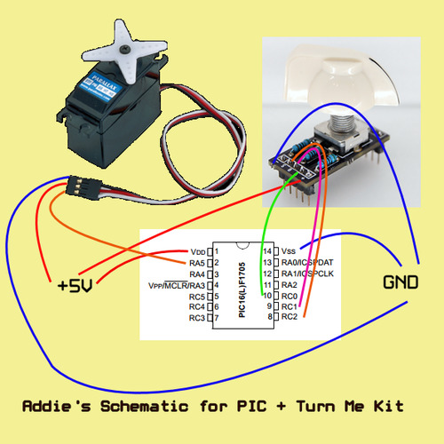
The Turn Me Kit + PIC16f1705
Today we'll be showing a demo video of a project our friend @wireengineer put together with a PIC16f1705 and the Turn Me Kit. The kit is a quadrature encoder with pulldown resistors and allows you to use one with only 5 wires: + / - / Switch / A / B
So we've done an example with the Propeller before: http://tymkrs.tumblr.com/post/52528466585/tymkrs-turn-me-rotary-encoder-breakout-kit
But we wanted to show it working with a PIC, and Peter suggested we show a servo reacting to the encoder being turned. And sure enough, the following information does just that. When you turn the encoder left, the servo turns left until it ends. When you turn the encoder right, the servo turns right until it ends. And when you push the switch on the encoder down, it centers from whereever it is.
Video: https://www.youtube.com/watch?v=5soQlJ73UNU
Code:
http://tymkrs.com/code/enc2servo.zip
Addie Style Schematic:
Enjoy!
@atdiy/@tymkrs
0 notes
Note
Hello,i am seting up a connection between a sensor connected to an xbee on one end an an xbee mounted on arduino uno on the other end,so everything seems to be fine and i am reading tha API frames on the serial monitor but only for a short time and then the Xbee on the arduino seems to lose connection with the other xbee can you explain what to do???
It's hard to say what it could be without seeing your code, and what the sensor is....
0 notes
Text
Update on #FTDIGate
Well that was quick.
It looks like FTDI's CEO posted the following on EEVBlog:
"We appreciate your feedback, comments and suggestions. As you are probably aware, the semiconductor industry is increasingly blighted by the issue of counterfeit chips and all semiconductor vendors are taking measures to protect their IP and the investment they make in developing innovative new technology. FTDI will continue to follow an active approach to deterring the counterfeiting of our devices, in order to ensure that our customers receive genuine FTDI product. Though our intentions were honourable, we acknowledge that our recent driver update has caused concern amongst our genuine customer base. I assure you, we value our customers highly and do not in any way wish to cause distress to them. The recently release driver release has now been removed from Windows Update so that on-the-fly updating cannot occur. The driver is in the process of being updated and will be released next week. This will still uphold our stance against devices that are not genuine, but do so in a non-invasive way that means that there is no risk of end user’s hardware being directly affected. As previously stated, we recommend to all our customers to guarantee genuine FTDI products please purchase either from FTDI directly or from one of our authorised distributors. http://www.ftdichip.com/FTSalesNetwork.htm If you are concerned that you might have a non-genuine device, our support team would be happy to help out. Yours Sincerely Fred Dart - CEO"
And it seems that Windows has heard the outcry:
"Yesterday FTDI removed two driver versions from Windows Update. Our engineering team is engaging with FTDI to prevent these problems with their future driver updates via Windows Update."
@atdiy/@tymkrs
0 notes
Text
#FTDIGate
On one of the rare days that Whisker and I aren't working on videos, software, hardware, woodworking, etc, I hang out in our IRC and catch up on the latest tech news. Yesterday it just so happened to be the debacle with FTDI's USB chip drivers that we coined #FTDIGate. (Because anything + Gate = MASSIVE CONTROVERSY).
FTDI is a company best known for their USB to serial chips which can be found on numerous cables, boards, dev kits, etc. As a result of this functionality's near ubiquitous use, there are many different chip options made by other companies such as Microchip, Cypress, Prolific, etc. However, there are many counterfeit chips who claim to be FTDI chips and therefore use their drivers.
So what do these drivers do? So when a USB device is plugged in, it has a specific VID/PID combination - with VID = Vendor ID and PID = Product ID. The PC uses this combination to find drivers (if any) that are to be used for the device. For this to work, the VID/PID combo must be unique in the sense that each USB device with the same VID/PID will use the same driver. Or in other words, if you need a specific driver, you will need a unique VID/PID for that product. (cite: http://www.voti.nl/docs/usb-pid.html)
There are two ways to get a VID number - become a usb.org member or buy a VID number - both costly options. Each VID number then gives you 65536 PID numbers. And PID numbers are given out by those who own VID numbers. So you can request them from FTDI or Microchip or whoever the VID owner is. Now because it is so costly, (annual fees for usb.org membership, set-up costs, etc), counterfeit chips often piggyback by setting their own product's VID/PID to that of a currently working set-up, in this case, FTDI's.
So over the past month, issues with various "FTDI" chips have surfaced, and have been found to be linked to the latest FTDI driver: http://hackaday.com/2014/10/22/watch-that-windows-update-ftdi-drivers-are-killing-fake-chips/
This update from FTDI can be found on the typical Windows update and what it does is essentially write a bunch of information to its FTDI chips and in doing so, "rewrites" the PID number of the counterfeit chips to 0000 - which as far as I am aware, is not associated with any particular product. What this ends up doing is making it so that that chip is out of commission until either the counterfeit chip can be reprogrammed, and given its old PID with a previous driver version.
There are two camps of opinion with a vast majority somewhere in between. I'll try to include some of the arguments made by both sides:
1) FTDI was absolutely right. They updated their own drivers for their own chips. They have no obligation to support counterfeit chips and are in fact protecting their intellectual property. If anyone's to blame, it's the manufacturers of the product who used the counterfeit chips instead of buying from reputable sources as well as the counterfeit chip makers.
If something is not working, people should send the item back to the manufacturer - or have them recall the product and fix it.
Engineers of large industrial items put more than one safeguard such that if by some fluke, a counterfeit chip enters into the system and is rendered useless by this, it's likely that the machine won't suddenly go haywire and kill all of its operators.
Medical related items are severely anal about where they get their parts from and track each part even down to the manufacturing lot.
Root out the wrong do-er in the chain of production who's providing the counterfeit chips and get rid of them - not FTDI!
Going after cloning vendors in China is not going to get you anywhere.
Truth of the matter is if a lay end user has something which stops working after the windows update, they'll go back to whoever sold them the item, who will then report that a massive batch of products are now messed up. This will allow the company selling the items to look back into their supply chain to see where the wrong party is and FIX the chips.
The chip's situation is completely reversible and is something that can be fixed. The chip wasn't suddenly given 1000v of juice to give up the smoke. The chip is NOT destroyed or bricked. Nor are the electronics past the chip. Fix the chip, you have your electronics back.
Counterfeiting is illegal. Buy the chips from reputable sources, and then bring it to their attention when something is wrong!
By using FTDI drivers, and not writing your own, you are accepting all responsibility with using those drivers. It's not FTDI's fault if it borks your chip which cannot be used with its drivers.
If you buy a clone board, expect counterfeit parts. Can't have your cheap cake and eat it too.
Companies should be in control of their supply chain anyway - it's good practice, and it allows you to not be caught with your pants down. Inconvenience now = popcorn for when counterfeiters are being brought down.
Take responsibility for not having the right parts on your boards manufacturers!
Counterfeiters should write their own drivers. Get their own VID/PIDs - because clearly they're making enough money to be so ubiquitous that board houses can't control the quality of the parts.
Ignorance of "lay people" is not a reason that counterfeiting chips should be allowed to continue populating boards and be allowed to keep working off of the PID of a legitimate chip.
2) FTDI was wrong to do this and it will backfire. They are hurting the end user instead of directly going after counterfeit chip manufacturers by suing them. And they could have used a gentler method of disabling - rather than reprogramming the chip - they could have had a pop-up, or merely not allow the chip to work with the driver.
With this update, items may just stop working and cause major damage - especially in industrial or medical settings.
There are many places where counterfeit FTDI chips could come into the system - board house, parts supplier.
End users may purchase a product in good faith from a reputable company, but the product itself may have been manufactured with a counterfeit product unbeknownst to the manufacturer due to supplier error. Don't punish the end users!
Asking the company to recall their products and fix the parts could lead to bankruptcy for the company and would not be feasible for most companies.
Property's now been bricked and destroyed. The chip's destroyed, and that's illegal.
People are just going to say, well, there could be fake FTDI chips that'll mess up my product, so we're not going to even bother with FTDI. This move backfired on them.
I'd rather have had them just disable the chip rather than maliciously re-programming it. It's the active reprogramming to render useless that is not okay.
Was this driver actually necessary or was it just to be malware against counterfeit chips?
There are so many counterfeits out there running in important hardware that it shouldn't have been disabled in that manner.
Auto-updaters are automatically pushing this potentially product-breaking update without consumers actually knowing that there is a chance their items will be effectively useless.
How do we know their detection mechanism for the driver won't also mess up their own chips?
What a polarized subject. I don't know the repercussions of FTDI having done this in the courts, but I do know that not all press is good press. And if you have additional arguments for or against, I'm all up for it.
So far general consensus is that FTDI has the right to defend their IP but not reprogram other companies' chips, even if they're counterfeit.
@atdiy/@tymkrs
3 notes
·
View notes
Text
How to use the TTL8 board!
The TTL8 board is a new board that we have recently put out on Tindie (https://www.tindie.com/products/tymkrs/tymkrs-ttl8-module/) and not only is it small and compact, it's quite useful for turning on and off low current loads such as LEDs.
The board consists of a shift register, 8 leds (or not), and headers for input into the shift register, output from the shift register, and header space for daisy chaining for multiple TTL8 boards. If you've ever worked with the 74hc595 shift register (or any shift register in general), the number of wires required to get one of those bad boys working is a pretty prohibitive pain in the butt. For example, see the following:
I'm anti clusters of wires. So the board takes all of those wires and puts them into a 5/8" x 1-1/8" footprint. As a stand-alone board, for just LED indication, you only need your microcontroller and 5 wires going to the Port In side: (from left to right) Power, GND, Latch, Clock, Serial.

Most of the microcontrollers I work with use 3.3v. And you can certainly connect the TTL8 board to the microcontroller, or you can, if you're daisy chaining a bunch of TTL8 boards, use the power and gnd header on the bottom left with greater current capabilities. Just note that voltage-wise, your uC voltage needs to be the same as that provided to the board. So if your microcontroller works off of 3.3v, provide your TTL8 board with 3.3v.
If you want the shift register to drive 8 other items, or even 8 LEDs that aren't attached to the board, that's how you'd use 0-7 header. The shift register is connected to all 8 of the pins and can drive whatever you'd like - within current limits of the shift register of course.
Whisker uses this board as a debug board - so if you want to check if your input device is actually working as expected, or sending signals as desired, you can have it light up the LEDs.
Code: http://pastebin.com/FZNQbUbf
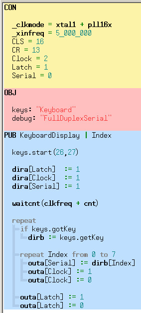
So this is of course using the Propeller microcontroller. I used the demo board and programmed it in Spin. In the main body of the program, the propeller sets the pins sending out Latch, Clock, and Serial as outputs. It then repeatedly monitors to see whether a key's been pressed. If it has, it puts it into register dirb.
And repeating from index 0 to 7, it spits out via serial what key has been pressed in register dirb. If you had 4 TTL8 boards chained together, you'd repeat index 0 to 31.
So it spits out the serial, then it outputs a 1 on the clock line to bring it high, then brings it low to signify that a bit has been set, and that the next bit can be set in the shift register. Then after all index values have been gone through, the latch is set high and low again. This feeds it out to the indicator leds, or to whatever you're driving.
And that's the TTL8 board! Again it's available: https://www.tindie.com/products/tymkrs/tymkrs-ttl8-module/ and if you have any questions, let us know!
@atdiy/@tymkrs
#ttl8 board#ttl8 module#shift register#74hc595#tymkrs#tindie#propeller#shift register and propeller#spin#driving leds with shift register
0 notes
Text
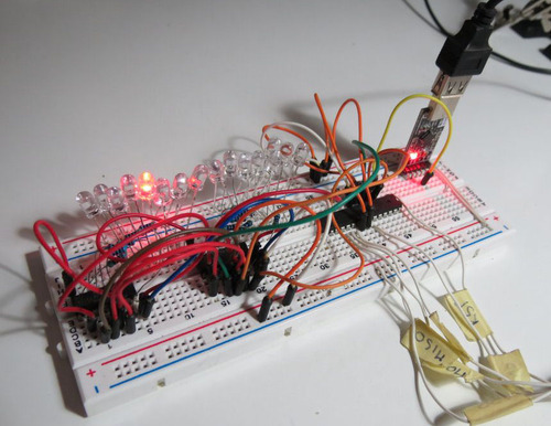
Going Postal: Clacks Towers - Step 2: Sending Binary
So the last post, I was able to at least test to see that the keyboard was working properly. Today I wanted to work more on trying to get the keyboard sending information to LEDs.
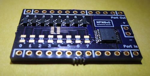
So connected I have the keyboard to the Parallax Demo Board. Then I have an NPN8 kit (one of our new kits) which allows you to send signals through a shift register (serial to parallel) and output onto 8 separate channels - in this case LEDs!
The NPN8 Kit has 5 connections on one side (from right to left) : Power, GND, Clock, Latch, Serial (In the Port In section). Pins 0-7 on the Port In side connect to the emitters of the transistors and Pins 0-7 on the Port Out side connect to the collectors of the transistors.
So from right to left in Port In: 3.3V, Ground, and put Clock, Latch, and Serial on Propeller Demo Board pins 2, 1, and 0 respectively (just because of how the wiring went).
Using the Tymkrs Shift Me example code (another kit), and with the help of Whisker, we shortened it and incorporated it into the keyboard code:
http://pastebin.com/FmiHMVmm
It essentially sets Latch, Clock, and Serial as outputs. Then looks at the keyboard. If a key is pressed, the key's information gets passed into variable Index as a long (32 bits). I left a debug line there so that if you wanted to see your typing on the serial terminal, you could.
Then I directed the Propeller to examine this variable Index, specifically bits 0 to 7. I then told it to send bits 0 to 7 out on Serial to the shift register.
Note, remember shift registers (serial to parallel), take 8 bits in serially, and pass them out in a parallel fashion. To do so, you send in a bit, the clock has to go high then low, rinse repeat. When you are ready to release the stored inforation, the latch has to go high then low.
Then as mentioned before, I sent in a bit, set the Clock to high, then low. And after 8 bits, set the Latch to high, then low. This process tells the shift register to release its stored bits. So whatever you typed, essentially shows up on the LEDs!
The board above is a TTL8, another upcoming kit and allowed me to test with the LEDs, on the board, whether the keyboard was sending the correct information and whether the LEDs were lighting up appropriately. The way it functions is pretty much the same as the NPN8. Only difference is instead of driving 8 transistors which drive the LEDs, the TTL8 board drives the LEDs directly from the shift register.
http://tymkrs.tumblr.com/post/53522451066/tymkrs-shift-me-chainable-shift-register-header-kit <-- for more information on how shift registers work.
IT WORKS! Now for cosmetics!!!
@atdiy/@tymkrs
#tymkrs#shift register#npn8#ttl8#parallax keyboard#parallax demo board#parallax#propeller#spin#keyboard and propeller
2 notes
·
View notes
Text
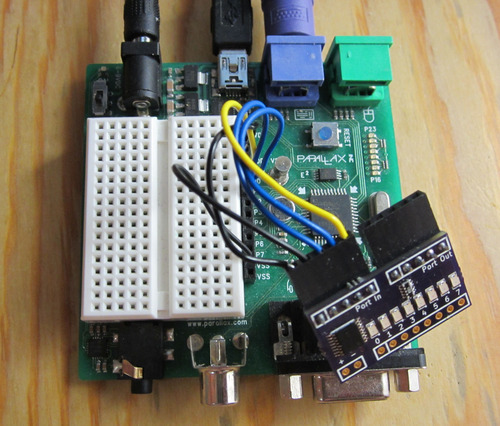
Going Postal: Clacks Towers - Step 1: The keyboard
Of Terry Pratchett's Discworld movies, I like Going Postal the most. The story's both interesting, hilarious, and they have fabulous technology - the clacks towers. These are a system of semaphore towers capable of spreading messages 1 letter at a time.
Instructables sent our hackerspace a bunch of LEDs and I thought it'd be a lot of fun if I made a semaphore tower with the LEDs for our hackerspace's monthly build night. But of course I wanted to make it easier to transmit messages, so I'll be incorporating a keyboard into the project.
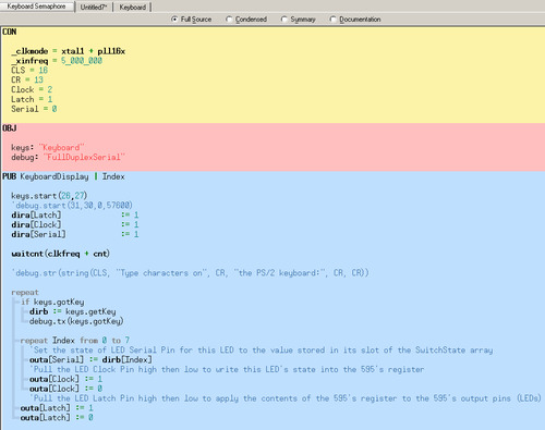
So I have a Parallax keyboard plugged into a Propeller Demo Board, and wanted to at least see that it worked. Note the purple port below!
I went to the OBJ to look for a keyboard demo, and found one but it didn't seem to do anything. So I looked around a bit more and found http://www.parallax.com/sites/default/files/downloads/28060-PS2-Adapter-v1.0.pdf . There was some test code:
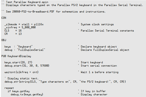
Which I put into PropTool. I then opened up the serial terminal (Run --> Parallax Serial Terminal) and pressed enable. I compiled the code on RAM and saw that as I typed letters, a red light appeared by the USB cable. This was all well, but nothing was showing up on the serial terminal.
So I looked for which COM port the keyboard was talking on (Run -> Identify Hardware) and saw it was a different COM than what was set on the serial terminal. As soon as I changed the COM port on the serial terminal, it was golden!
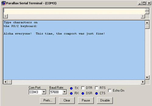
Don't forget to make sure your baud rate is 57600!
The next step for me is to try to get the keyboard to send the binary of each letter out through our latest kit NPN8 to some LEDs!
@atdiy/@tymkrs
3 notes
·
View notes
Text
Context is everything
Just as a follow-up to this article, I haven't been through the ENTIRE process, but have certainly been witness to what it all involves. Essentially after writing a paper, you send it off to a journal, who then chooses 3-4 reviewers from your field to review your paper. They rip it to shreds, find what data still needs to be done, and then come back with their red pen telling you what's what. That's called a peer-review. And you either rebutt or you add on to your research to answer their questions.
The reason peer-review is important is because while YOU may be convinced about the results and what the results mean, your job as a scientist is to demonstrate proof to others who are equally qualified to analyze your data. The peer reviewer is meant to make your data become above-reproach.
So it was interesting when I read this comment, in response to the article I've been reading through: http://www.plosone.org/annotation/listThread.action?root=53905
This team expressed quite a few concerns about the article, many of them which I have not vetted, but is worth considering because it largely considers the study negligent and over-exaggerating of its results. It's all because of context. I'd advise you take some time to read through the answer, it's pretty interesting and informative.
This also touches on why I think it's interesting that this particular study, performed at a rather prestigious center, would send this sort of article to PLOS One as opposed to a more well known journal. Because if indeed this data is sound and if the technique is sound, then it has fairly significant findings that a journal would be happy to pick up.
The following is the peer review "About Us" for PLOS ONE: "Often a journal's decision not to publish a paper reflects an editor's opinion about what is likely to have substantial impact in a given field. These subjective judgments can delay the publication of work that later proves to be of major significance. PLOS ONE will rigorously peer-review your submissions and publish all papers that are judged to be technically sound. Judgments about the importance of any particular paper are then made after publication by the readership, who are the most qualified to determine what is of interest to them."
I don't know what kind of peer review this went through, but from the one review done by the commenter, it seems not enough.
@atdiy/@tymkrs
#the flip side#tymkrs#peer review#plos one#ritalin#dopaminergic neuron#dopaminergic system#chronic ritalin
1 note
·
View note
Text
Ritalin and Dopaminergic System Part 6
Following article courtesy of @lmcomie:
http://www.plosone.org/article/fetchObject.action?uri=info%3Adoi%2F10.1371%2Fjournal.pone.0033693&representation=PDF
Sadasivan, S., Pond, B.B., Pani, A.K., Qu, C., Jiao, Y., & Smeyne R.J. (2012) Methylphenidate Exposure Induces Dopamine Neuron Loss and Activation of Microglia in the Basal Ganglia of Mice. PLOSONE, 7(3).
Last post about this article! I finally found some time to go through the materials and methods. So St. Jude Children's Research Hospital was where this research was done. The mice were 3 weeks old and maintained on a 12h light/dark cycle (this is normal). Starting when they were 28 days (this is about young adulthood/just off weaning), they were given injectsion of saline, 1mg/kg or 10mg/kg Ritalin at 5pm - 1 hour before their active nocturnal phase at 6pm.
Doses were chosen sbased on previous studies in rodents suggesting that Ritalin doses of < 5mg/kg mirror those that are used in clinical practice, as opposed to recreational and narcoleptic use = dose of 10mg/kg.
Ritalin injections were given 5 days a week and at the end of the 12 weeks, the animals were allowed a washout period of a week.
After the week of washout, the mice were anesthetized and euthanized. The method they describe is fairly common for brain analysis. And then the brain was sliced to 10um thick for analysis. I can't tell if they had to count neurons by eye or not, but they mentioned using a "optical fractionator method" - it may be some sort of estimating tool developed with a specific microscope in mind.
For MPTP treatment, the final concentration was 5mg/ml and each animal was given 4 injections of 20 mg/kg MPTP - one every 2 hours for 8 hours. All mice then stayed around for a week after the injections, before euthanization.
The rest of the article describes the methods they used for measuring mRNA and expression signals - unfortunately not my forte - but still a well documented method in many different studies.
I think one thing to note is that the n levels (number of subjects) that they tested throughout these experiments is relatively low compared to how many mice are usually put through an experiment. The n numbers are anywhere from 3 to 8. This is not very high. IE. They're using the results from 3 mice to come to this conclusion. The research would have been much stronger had there been at least 10 mice per category. The logistics, however, would have been difficult. (Why? Cuz mice don't like injections anymore than humans do)
@atdiy/@tymkrs
0 notes