
Don't wanna be here? Send us removal request.
Statistics
We looked inside some of the posts by physicalcomputing-ashleybending1 and here's what we found interesting.
Average Info
Notes Per Post
0
Likes Per Post
0
Reblog Per Post
0
Reply Per Post
0
Time Between Posts
4 days
Number of Posts By Type
Text
12
Last Seen Tumblr Blogs


Fun Fact
Mobile Tumblr US users spend an average of 4.04 minutes per session on the app.
Text
Final Project - Rubber Ducky bath sensor & accompanying app
Google Drive Link:
https://drive.google.com/drive/folders/1uXXbHXMaI9CPLH9V-Sr-x84OueIPxLh_?usp=sharing
- Parts used
1 x Arduino
1 x HC-05 Bluetooth Module
1x Ds18B20 Waterproof Temperature Sensor
4x 2K Resistors
Jumper wires
Rubber duck
Electrical tape
Videos:
Bluetooth Connection Process:
youtube
Duck usage video & real world example along with App
youtube
Selected Temperature Reached:
youtube
Photo of circuit:

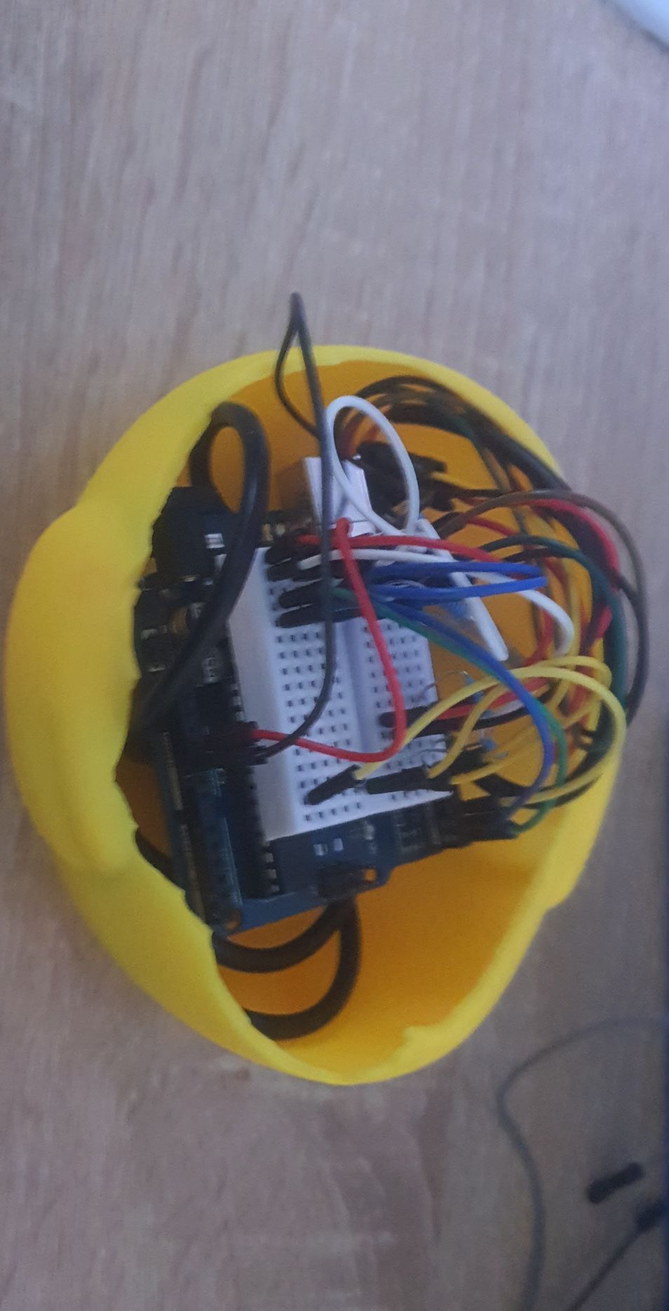

Circuit diagram:
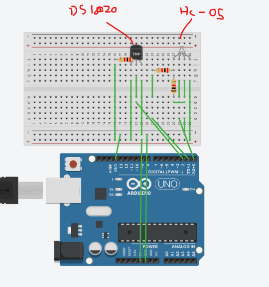
(Some wires have been ommitted for clarity sake, but on the small breadboard i added some extra wires bridging the gap so i could use the I/O from the same side which is why it might look slightly different on the diagram, but functionally it is the same. )
Code:
#include <OneWire.h> int DS18S20_Pin = 2; //DS18S20 Signal pin on digital pin 2 //Temperature chip i/o OneWire ds(DS18S20_Pin); // on digital pin 2 void setup(void) { Serial.begin(9600); } void loop(void) { float temperature = getTemp(); Serial.println(temperature); delay(100); //to slow down the output so it is easier to read } float getTemp(){ //returns the temperature from one DS18S20 in DEG Celsius byte data[12]; byte addr[8]; if ( !ds.search(addr)) { //no more sensors on chain, reset search ds.reset_search(); return -1000; } if ( OneWire::crc8( addr, 7) != addr[7]) { Serial.println("CRC is not valid!"); return -1000; } if ( addr[0] != 0x10 && addr[0] != 0x28) { Serial.print("Device is not recognized"); return -1000; } ds.reset(); ds.select(addr); ds.write(0x44,1); // start conversion, with parasite power on at the end byte present = ds.reset(); ds.select(addr); ds.write(0xBE); // Read Scratchpad for (int i = 0; i < 9; i++) { // we need 9 bytes data[i] = ds.read(); } ds.reset_search(); byte MSB = data[1]; byte LSB = data[0]; float tempRead = ((MSB << 8) | LSB); //using two's compliment float TemperatureSum = tempRead / 16; return TemperatureSum; }
Explanation:
The duck transmits the temperature by the Bluetooth module, to the app which then takes that and gives the user a notification (quacks) when the selected temperature is reached, it also tells them whether or not to add hot / cold water.
Since I used the TX/RX pins on the Arduino, no extra code was really needed since it transmits directly from the serial to the app.
Troubleshooting required: Quite a bit of troubleshooting was needed on this one, the duck ran out of battery half way though testing and the new battery I bought was substantially heavier than the last which meant the duck was barely able to float, so i had to search around for a cheaper battery because generally they are lighter than the more expensive ones, the next was for some reason the Bluetooth transmitter wouldn’t rename and didn't want to accept AT commands, it turned out i had a resistor one pin to many over so whilst the HC-05 was technically on it couldn’t transmit because it had no connection. another problem was that a week before this assignment was due, my boiler broke down, so a project that relied heavily on the idea that hot water could be used was kind of obsolete. Evaluation: Since originally i wanted to use a servo to turn the tap depending on whether or not hot water was required but due to a boiler breakdown this couldn’t be used, I’d say the project was semi successful, since the duck and app work nicely together as a closed system, I was more than happy with the result, but feel it could be improved upon by the inclusion of the tap module.
Difficulties others may encounter: See troubleshooting required
0 notes
Text
Experiment for Final project expansion - 20kg servo tap Test
- Parts used
Arduino
DS3218MG Servo
Electrical tape
Video:
youtube
Photo of circuit:

Circuit Diagram:
Code:
#include <Servo.h>
Servo myservo; */
void setup(){
myservo.attach(9);//connect pin 9 with the control line(the middle line of Servo) myservo.write(90);// move servos to center position -> 90° } void loop(){
myservo.write(0);// move servos to center position -> 120° delay(1000);
myservo.write(180);// move servos to center position -> 120° delay(1000); }
Explanation:
this was a simple test to see if the strength of the servo could handle pulling the tap from off to on.
Troubleshooting required: initially i tried a servo that was far too weak, I’ll also potentially need to include a strong base, although the design i have in mind should reduce the strain on the servo and be strong enough to hold it.
Evaluation: since using a stronger servo was a must for this Difficulties others may encounter: Making sure the correct pin is initialised and knowing which way the servo is going to turn is a help and making sure that the Arduino has a sufficient power supply to the servo, or using a separate power supply.
Difficulties others may encounter: Making sure the correct pin is initialised and knowing which way the servo is going to turn is a help and making sure that the Arduino has a sufficient power supply to the servo, or using a separate power supply.
0 notes
Text
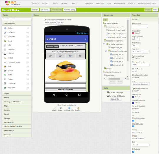
MIT app inventor setup
- Parts used
MIT app inventor 2
android smartphone
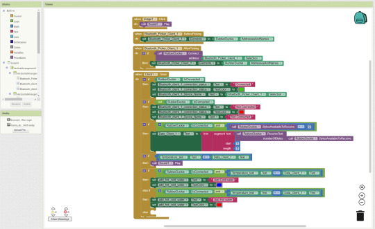
Code:
Since the code is written in codeblocks ill explain them line by line here
Block 1:
When the image is clicked, it plays a quack sound (sound1)
Block 2:
This is setup for the Bluetooth picker, it allows you to set a device that has already been paired to your phone from a picker list, it then resets the picker in case you want to reselect
Block 3:
After a client is picked, it attempts a connection to that Bluetooth address, it then resets the picker in case you want to reselect
Block 4:
The clock element acts similar to the Loop function in the Arduino IDE, running off of an RTC it Updates and re-runs code
First IF statement:
This changes onscreen text elements if the Bluetooth client is connected, it sets the text to connected, the text colour to green and the connected device text to the address and name of the connected Bluetooth device
Second IF statement:
This changes onscreen text elements if the Bluetooth client is not connected, it sets the text to Not connected, the text colour to red and the connected device text to Not connected
Third IF statement:
This part trims the text received from attached Bluetooth device, since the DS18B20 returns temperature accurate to 2 decimal places, as well as multiple outputs of it on the same line through the serial, this is displayed as a long string in the app, to get around this, If the Bluetooth client is connected and there is a amount of bytes incoming, It receives the bytes and converts them to text (ASCII codes => TEXT) then it sets the onscreen text after trimming the text (removing the spaces) and then taking a single segment of 2 length starting at the first character (removing both the decimal places and the rest of the characters)
Fourth IF statement:
if the temperature input from the DS18B20 is the same as the temperature selected, then it plays a quacking sound.
fifth IF statement:
If the Bluetooth client is connected and then the temperature of the water is more than the selected temperature, it sets the onscreen text to add cold water and sets the colour to blue.
Sixth IF statement:
If the Bluetooth client is connected and then the temperature of the water is more than the selected temperature, it sets the onscreen text to add hot water and sets the colour to red.
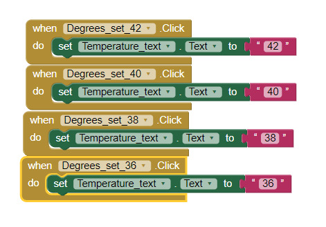
Block 5:
these are the code blocks that set a temperature for the program to aim for.
Troubleshooting required: Originally I couldn’t work out why it returning an array from the Bluetooth client, hence the application of text trimming and segmentation.
Evaluation: I was pleasantly surprised at how simple it was to create an app to use along side the project and it only took about an hour messing around with MIT app inventor before i felt confident enough to build the actual application which is relatively fast for a new piece of software.
Difficulties others may encounter: Since this is a pretty specific use-case, the only difficulties i would think that other people encounter is with how they connect to Bluetooth, the way I’ve done it is the only way you’re supposed to apparently, as other ways can cause issues with the app.
0 notes
Text
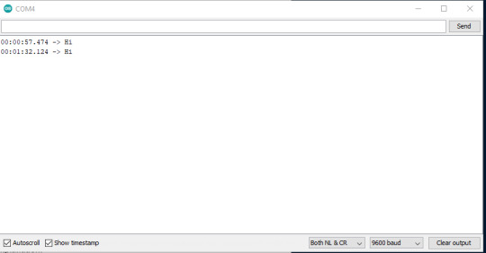
Bluetooth AT commands
- Parts used
Bluetooth HC-05 module
1x 1k resistor
1x 2k resistor
Jumper wires
Arduino
Photo of circuit:

Renaming the bluetooth module:

Code:
SoftwareSerial BTSerial(10, 11); // RX | TX
void setup() {
Serial.begin(9600); Serial.println("Enter AT commands:"); BTSerial.begin(38400); // HC-05 default speed in AT command }
void loop() {
if (BTSerial.available()) { // read from HC-05 and send to Arduino Serial Monitor Serial.write(BTSerial.read()); }
if (Serial.available()) { // Keep reading from Arduino Serial Monitor and send to HC-05 BTSerial.write(Serial.read()); }
Explanation:
The two resistors are used as a way of dividing voltage, since the receiver (RXD) pin of the only accepts 3.3v and the output of the pins on the Arduino is 5v, this is done to prevent overvoltage.
The inclusion of the software serial means that instead of using the TX / RX (pin 0 / 1) which can cause problems when trying to upload new code, you can use the PWM pins to replicate this and avoid issues. (on the final project, since the duck doesn’t need usb access whilst being used, the 0/1 pin will be used)
Troubleshooting required: See difficulties others may encounter
Evaluation: My first adventure into wireless communications was far more successful than i thought it would be, I genuinely thought that it would be more difficult than it was. something i could have improved is making some kind of basic call and response in the program using a switch just to extend my skills a small amount.
Difficulties others may encounter: Initially i used the TX/RX pin 0/1 on the Arduino, not realising this would cause issues with the board, to remedy this you can use the software serial function
0 notes
Text
Bluetooth Setup (HC-05 Bluetooth Module)
- Parts used
HC-05 Bluetooth Module
1x 1k Resistor
1x 2k Resistor
Arduino
Jumper Wires
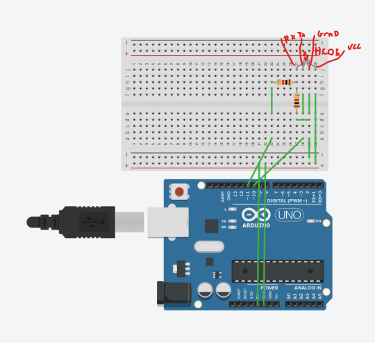
Photo of circuit & software:


Code:
#include <SoftwareSerial.h>
SoftwareSerial Bluetooth(10, 11); // RX | TX
void setup() { Serial.begin(9600); Bluetooth.begin(9600); }
void loop() { if (Bluetooth.available()) Serial.write(Bluetooth.read()); if (Serial.available()) Bluetooth.write(Serial.read()); }

(Ignore the use of the RGB LED, its because it had 4 pins and sits similarly to the HC05 - i have noted which pins are which above it)
Explanation:
The two resistors are used as a way of dividing voltage, since the receiver (RXD) pin of the only accepts 3.3v and the output of the pins on the Arduino is 5v, this is done to prevent overvoltage.
The inclusion of the software serial means that instead of using the TX / RX (pin 0 / 1) which can cause problems when trying to upload new code, you can use the PWM pins to replicate this and avoid issues. (on the final project, since the duck doesn’t need usb access whilst being used, the 0/1 pin will be used)
Troubleshooting required: See difficulties others may encounter
Evaluation: My first adventure into wireless communications was far more successful than i thought it would be, I genuinely thought that it would be more difficult than it was. something i could have improved is making some kind of basic call and response in the program using a switch just to extend my skills a small amount.
Difficulties others may encounter: Initially i used the TX/RX pin 0/1 on the Arduino, not realising this would cause issues with the board, to remedy this you can use the software serial function
0 notes
Text
The death of a rubber ducky ( DS18B20 Temperature Sensor test)
- Parts used
DS18B20 Temperature Sensor
4.7k Resistor
Photo of circuit:


Circuit diagram:

(Replaced DS18S20 with tinkercads temperature sensor)
Code:
#include <OneWire.h> int DS18S20_Pin = 2; //DS18S20 Signal pin on digital pin 2 //Temperature chip i/o OneWire ds(DS18S20_Pin); // on digital pin 2 void setup(void) { Serial.begin(9600); } void loop(void) { float temperature = getTemp(); Serial.println(temperature); delay(100); //to slow down the output so it is easier to read } float getTemp(){ //returns the temperature from one DS18S20 in DEG Celsius byte data[12]; byte addr[8]; if ( !ds.search(addr)) { //no more sensors on chain, reset search ds.reset_search(); return -1000; } if ( OneWire::crc8( addr, 7) != addr[7]) { Serial.println("CRC is not valid!"); return -1000; } if ( addr[0] != 0x10 && addr[0] != 0x28) { Serial.print("Device is not recognized"); return -1000; } ds.reset(); ds.select(addr); ds.write(0x44,1); // start conversion, with parasite power on at the end byte present = ds.reset(); ds.select(addr); ds.write(0xBE); // Read Scratchpad for (int i = 0; i < 9; i++) { // we need 9 bytes data[i] = ds.read(); } ds.reset_search(); byte MSB = data[1]; byte LSB = data[0]; float tempRead = ((MSB << 8) | LSB); //using two's compliment float TemperatureSum = tempRead / 16; return TemperatureSum; }
Explanation:
The first image is testing how waterproof the inserted DS18B20 is inside of the rubber duck, the tape inside was eventually replaced by electrical tape on both sides to prevent water from getting inside. The second image is the circuit
Troubleshooting required:
see difficulties others may encounter
Evaluation: This is a simple test circuit to see how the data is displayed from the DS18B20, the only thing that could be improved is that apparently the DS18B20 doesn't need the 4.7k pullup resistor, meaning you could make it more eco friendly.
Difficulties others may encounter:
The ends of the wires on the DS18B20 were very short, so I ended up having to strip the wires down a bit, cut a jumper wire in half, breaking out the soldering iron and then using the Frankenstein-ed wires inside of the duck for the final project
0 notes
Text
Infographic

Explanation:
The piece is an investigation into the history and evolution of Nintendo’s handheld gaming consoles hardware. The piece ranges from 1980 to present and details the specifications of each handheld device, including but not limited to: The type of battery(s) used, the processor model / clock speed, Co-Processor / clock speed, the GPU / clock speed / size of the VRAM, size of the DRAM, the size of the storage, the type of screen used as well as the resolution. I chose the timeline format because of its use within other infographics as well as providing a clear way for the reader to progress through the infographic.
0 notes
Text
Experiment 2 - Cardboard walker
- Parts used
UNO R3
Breadboard
Power Supply Module
2x ULN2003 Stepper Motor Driver Module
2x Stepper Motor
Joystick Module
16x wire
M3 sticky pad
Cardboard
Video:
youtube
Photo of circuit:

Code:
#include <Stepper.h> const int stepsPerRevolution = 200; Stepper myStepper(stepsPerRevolution, 8, 9, 10, 11); Stepper mySteppertwo(stepsPerRevolution, 6, 5, 3, 2); const int X_pin = 0; const int Y_pin = 1;
void setup() { myStepper.setSpeed(60); } void loop() { if ((analogRead(Y_pin)) < 400) { myStepper.step(stepsPerRevolution); mySteppertwo.step(-stepsPerRevolution); } if ((analogRead(Y_pin)) > 600) { myStepper.step(-stepsPerRevolution); mySteppertwo.step(stepsPerRevolution); } }
Explanation:
A combination of both the joystick and the stepper motors, using some triangular cut cardboard lets it step forward since the stepper motors are on opposite sides, in the code it is reversed (-stepsPerRevolution)
0 notes
Text
Experiment one - Joystick Direction LEDs
- Parts used
UNO R3
Breadboard
Joystick Module
4x LED
9x Wire
Video:
youtube
Circuit Diagram:

(Since tinkercad doesn’t have a joystick, I have used four pushbuttons to replicate the functionality of it and connected them to the same parts as the joystick would be)
Code:
const int X_pin = 0; const int Y_pin = 1;
void setup() { pinMode(6, OUTPUT); pinMode(5, OUTPUT); pinMode(4, OUTPUT); pinMode(3, OUTPUT); Serial.begin(9600); }
void loop() { if ((analogRead(Y_pin)) < 400) { digitalWrite(6, HIGH); } else { digitalWrite(6, LOW); } if ((analogRead(Y_pin)) > 600) { digitalWrite(5, HIGH); } else { digitalWrite(5, LOW); } if ((analogRead(X_pin)) > 600) { digitalWrite(3, HIGH); } else { digitalWrite(3, LOW); } if ((analogRead(X_pin)) < 400) { digitalWrite(4, HIGH); } else { digitalWrite(4, LOW); } }
Explanation:
Depending on the direction the joystick is pointing, a LED will light up for that corresponding direction. This is done through the use of code, when the Uno detects that a analogue input is above 600 or below 400, an LED will light up.
Troubleshooting required: One issue I encountered was matching the pins to the right x/y values it was a tedious process making sure each pin was correct for the direction that the joystick was being pushed
Evaluation: The first of my own experiments, this was a simple way of messing around with the analogue values that came out of the joystick, this could be improved upon by adding more joysticks, or more LEDS to represent diagonal values.
Difficulties others may encounter: forgetting to use Resistors, you need to be careful about this since initially i also did this, its possible to burn out an LED doing this
0 notes
Text
Stepper Motor
- Parts used
UNO R3
Breadboard
Power Supply Module
ULN2003 Stepper Motor Driver Module
Stepper Motor
7x Wire
Video:
youtube
Circuit diagram:

(Taken from https://www.tinkercad.com/things/jsXkBTAsRVu-stepper-motor-4-pairs-and-l293d since they have no driver module (ULN2003AN) and is a H-bridge but this is kind of the closest thing so it is not accurate to the real world, but works in a similar way.)
Code:
#include <Stepper.h> const int stepsPerRevolution = 200; Stepper myStepper(stepsPerRevolution, 8, 9, 10, 11);
void setup() { myStepper.setSpeed(60); Serial.begin(9600); }
void loop() { Serial.println("clockwise"); myStepper.step(stepsPerRevolution); delay(500); Serial.println("counterclockwise"); myStepper.step(-stepsPerRevolution); delay(500); }
Explanation: The inclusion of stepper.h allows control of the stepper motor and the accompanying controller board
Troubleshooting required: Initially i had my own 9v battery around so i had used that, before embarking on any project, it’s best to make sure batteries you use actually work. Took me a while to figure it out too.
Evaluation: Interesting introduction to stepper motors, something that could have been improved is either learning how to use more than one stepper at the same time to create some kind of simple moving car, or learning more about the applications of stepper motors vs servos
Difficulties others may encounter: Getting the input pins could be confusing to people new to Arduinos, along side making sure you use a separate power supply to drive the motors because if you don't it will not work.
0 notes
Text
Servo
- Parts used
UNO R3
Servo motor SG90
3x wires
Video:
youtube
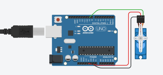
Circuit diagram:

Code:
#include <Servo.h>
Servo myservo; int pos = 0;
void setup() { myservo.attach(9); }
void loop() { for (pos = 0; pos <= 180; pos += 1) { // in steps of 1 degree myservo.write(pos); delay(15); }
for (pos = 180; pos >= 0; pos -= 1) { myservo.write(pos); delay(15); } }
Explanation: The code includes the library servo.h, which allows the assignment of a servo to a pin and then that is controlled by sending pulses from the UNO to the servo.
Troubleshooting required: Understanding how a digital servo works is a must for this project, whilst the accompanying documentation was sufficient in explaining how they worked, it took me a little bit longer to understand how the code worked, i had to go back and look through it a few times before I was confident with it. Also making sure that the Arduino has a sufficient power supply to the servo, or using a separate power supply.
Evaluation: Probably one of the simpler but cool projects we did since actually moving something in the real world after entering in the code felt kind of awesome, the introduction to servos was interesting, the way i would suggest improving this is either using a stronger servo or using a separate power supply.
Difficulties others may encounter: Making sure the correct pin is initialised and knowing which way the servo is going to turn is a help and making sure that the Arduino has a sufficient power supply to the servo, or using a separate power supply.
0 notes
Text
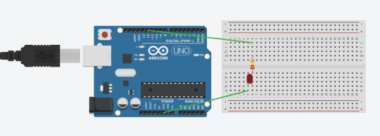
Blinking onboard LED & Blinking LED on breadboard
------------ PT 1. ------------
Blinking Onboard LED
-Parts used:
UNO R3
Video:
youtube
Circuit diagram: N/A (All onboard)
Code:
void setup() { pinMode(LED_BUILTIN, OUTPUT); } void loop() { digitalWrite(LED_BUILTIN, HIGH); delay(1000); digitalWrite(LED_BUILTIN, LOW); delay(1000); }
Explanation:
The onboard LED is blinked through the use of code, void Setup Initialises the pin on the Uno, then the loop sets the led to to high voltage (5v), then low voltage (0v)
Troubleshooting required: N/A
Evaluation:
Simple to look at but enjoyable to do as a starter project. Learning about how the digital pin modes work and delays worked was fun.
Difficulties others may encounter:
N/A unless your microcontroller is broken.
------------ PT 2. ------------
Blinking Breadboard LED
-Parts used:
UNO R3
Breadboard
2x Wire
220 Ω Resistor
LED
Video:
youtube
Code:
void setup() { pinMode(12, OUTPUT); } void loop() { digitalWrite(12, HIGH); delay(1000); digitalWrite(12, LOW); delay(1000); }
Explanation:
This is basically the same as the initial blinking LED, however instead of being on the board itself, its run through a circuit, functionally it is the same
Troubleshooting required: Whilst a relatively simple fix, this being my first proper introduction into electronics, getting the LED the right way round
Evaluation:
Simple to look at but enjoyable to do as a starter project. Learning about how the digital pin modes work and delays worked was fun. It could be improved by adding more LED’s and then timing them so they blink consecutively would be the next step.
Difficulties others may encounter:
Turning the LEDs the right way round. Fixing this is simple. Turn them around.
0 notes