#14 gauge thickness in mm
Text
Sheet Metal Gauge Chart
Discover a comprehensive Sheet Metal Gauge Chart, provides valuable information on gauges, thicknesses, and measurements. Find out the equivalent of 14 & 16 gauge thickness in mm and explore the world of gauge sheet metal.
#Sheet Metal Gauge Chart#Metal Gauge Chart#gauge sheet metal#16 gauge thickness in mm#14 gauge thickness in mm
0 notes
Text
I finally published the project for my dice roll scarf that went viral last month. If you love dice games, you'll enjoy knitting this pattern.

The color work in this project is determined by an algorithm, a set of rules that determine the final outcome. There isn't an exact set of instructions for this project. Instead, the knitter uses four 10-sided dice or a random number generator to pick the length of the colorwork in each row.
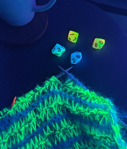
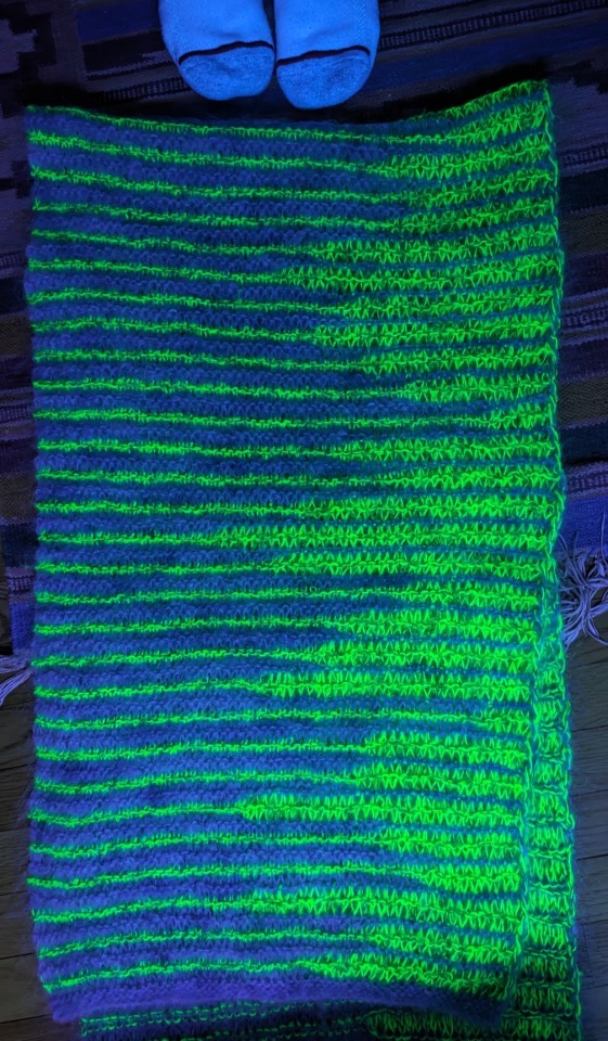
The result is a staggered stripe sequence along the edge of the shawl. There are trillions of unique outcomes, so no two projects turn out exactly alike. The pattern uses about 500 yards of yarn in total, but the amount of each color that you'll need is randomly determined. Before publishing, I wanted to find out the minimum and maximum amount of each color required to make the project and the probability of each outcome.

The knowledge needed to calculate the yardage was a bit beyond my skill level, but my friend Mary W. Martin helped me gather this info. I used an online probability calculator to find out the probability of each unique stitch count. The results are slightly different depending on whether you use four 10-sided dice (blue) or pick a random number (yellow), but 99% of all possible results fall within a very small range.
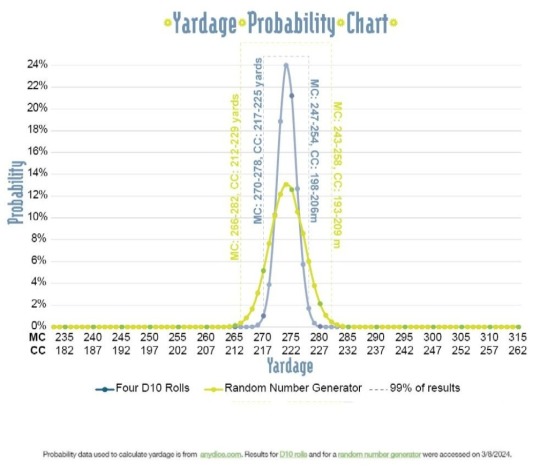
It was an interesting little tangent, but not hugely important to the actual knitting pattern. I can, however, confidently say there is a >99.9% chance that you'll need a 2nd skein of the main color. If you want to know more about the math, you should check out my project notes on Ravelry.
The thick and thin striped colorwork is created with a super simple "long stitch" technique. The pattern looks great in fluffy mohair or contrasting colors of basic wool and the instructions include some basic tips for substituting yarns or changing the gauge.


Finished Size: 18 x 68” (46 x 172 cm) rectangular wrap.
Yarn: Approx. 315 yards (288 m) of MC and approx. 264 yards (241 m) of CC. Yardage may vary, see notes on yardage below and yardage chart in photos.
• Main Color (2 skeins) - JMR Studio Worsted Weight Mohair, 245 yards (225 m) per 4 oz; 78% Mohair, 13% Wool, 9% Nylon.
• Contrast Color (1 skein each, both yarns held together) - JMR Studio Fingering Weight Mohair, 320 yards (293 m) per 100g; 63% Silk, 23% Kid Mohair, 11% Nylon, 3% Polyester Held with Lavender Lune Yarn Co. Suri Alpaca, 328 yards (300 m) per 50g; 74% Suri Alpaca, 26% Silk.
Yardage: The amount of each color used for this pattern fluctuates based on the random numbers used to determine the stitch pattern. MC uses approx. 233 to 315 yards (213 to 288m) and CC uses approx. 182 to 264 yards (166 to 241m). 99% of possible results fall within a much smaller range. The Yardage Chart shows the distribution of all potential yardage outcomes.
Needles: Size 8 (5 mm) straight needles, or size needed to obtain gauge. NOTE: Straight needles work best with long stitches. Circular needles with a thin cord allow the long stitches to tighten and stretch, making them harder to manipulate.
Gauge: 12 sts x 14 rows = 4 x 4” (10 x 10 cm) square in pattern.
Other Materials: 10 sided die or random number generator, stitch marker, scale, tapestry needle.
Generating numbers: In my sample, I used four ten-sided dice (D10) to choose a number between 4 and 40 sts. If you don't have dice, you can use an online app like RANDOM.org to generate your numbers. If you follow this link, you'll get a list of 63 integers between 4 and 40. NOTE: Each time you visit the link or refresh the page, the list changes. You can also just choose numbers as you knit.
Pattern is available on my website and on Ravelry.
809 notes
·
View notes
Text


PAIR OF GAUGE 14 x 19 x 5 MM, BARBELLS BODY PIERCING JEWELRY SURGICAL STEEL 316 L CLEAN.
THIS LISTING IS FOR A PAIR OF MATCHING BARBELLS. THEY MEASURE 14 GAUGE (THICKNESS - SEE PHOTOS), LENGTH OF BAR, 19 MM (3/4") WITH 5 MM BALLS ON BOTH ENDS (USUALLY ONE END SCREWS OFF ONLY, SOMETIMES 2, both) SEE PHOTOS. YOU CAN TAKE OFF ONE OF THE BALLS AND SCREW MOST 14 GAUGE ATTACHMENTS ONTO IT AS WELL -- TO CHANGE UP YOUR LOOK.
19 MM LONG BAR, OR 3/4" INCH EQUIVALENT. 5 mm screw on balls are are 1 size smaller than 6 mm balls, for comparison.
MANY OTHER LENGTHS AND SIZES ARE AVAILABLE ON MY DAWNETT'S EMPORIUM STORE.
I AM A PROFESSIONAL PIERCER, SO YOU CAN BE SURE MY MEASUREMENTS OF JEWELRY ARE RIGHT AND CORRECT. I ALSO HAVE INCLUDED TWO PHOTOS OF MEASUREMENT CHARTS, TO HELP YOU KNOW WHAT SIZES YOU WANT AND/OR NEED, FOR YOUR PARTICULAR BODY PIERCINGS. WRITE ME WITH ANY QUESTIONS.
#DAWNETTSEMPORIUM, #BEAUTIFULMERMAIDQUEEN, #SHAUNALYNNS FOOD.
FREE SHIPPING. VOLUME PRICING, THANK YOU!
2 notes
·
View notes
Text

What is the thickness of an electrical wire?
The thickness of an electrical wire can vary depending on its gauge or size. Wire thickness is typically measured in American Wire Gauge (AWG) or metric units. AWG uses a numerical system, where smaller numbers indicate thicker wires. Common household wires range from 14 AWG (1.6 mm) for light fixtures to 10 AWG (2.6 mm) for larger appliances. Industrial applications may require even thicker wires. It's important to consult electrical codes and regulations specific to your region to determine the appropriate wire thickness for a given application.
#commercialelectricalservice#electricalservicesnearme#electricrepairservice#electricalservice#electricalcontractors#electricalcontractorsnearme#contractorelectric#contractorelectrical
0 notes
Text
The Global Aluminum Foil By using Lid Market
Aluminum foil is really a thin sheet of metal containing many different employs, including in the actual kitchen. It can often line baking bed sheets, wrap food or mask to keep seepage in. It is safe to utilize in the stove, and can aid prevent burns. It may also be used to keep food from being dedicated to the pan.
Foil with lid is a type of aluminium foil that includes a cover. It is required in food packaging so when a decorative equipment for homewares. It will always be precut to the size of a containers. It is your lightweight and resilient packaging material this improves the shelf life of the product.
The global aluminum foil with street bike market is supposed to see a high growth through forecast period. This is because of increasing consumption associated with packaged food plus beverages products and also growing demand pertaining to disposable aluminum lids.
Moreover, the increase inside organized retail sector is anticipated for you to drive the growth on this market during the actual forecast period. Furthermore, technological advancement inside the packaging industry will boost the market growth further.
With regard to yoghurt, aluminium foil is used for heat wrapping up of plastic cups to produce maximum protection. This packaging technique is widely used in Europe.
These foil truck tops are normally embossed as well as the gauge of these lids is around 40 mm. They may be typically packed in the magazine of 2500-3000 truck tops to minimise hardware damage.
In add-on, they are for sale in different thicknesses – 40, 35 or 38 microns. These are used for finalizing containers of jars, cups and casseroles to protect their contents.
Ffortunately they are widely used inside food processing industry to safeguard foods such when milk, cheese, plus butter. They have the ability to withstand temperature changes and are also resistant to abrasion and chemicals.
The European location is accountable for 14% with the global aluminum foil with lid market share and it is projected to grow further through forecast period on account of increased demand to get ready-to-eat meal solutions. Moreover, the initiatives through governments to inspire food exports and also decarbonization targets are predicted to further improve the regional marketplace.
North America region is estimated to contribute 19% from the global aluminum foil using lids market in fact it i anticipated to retain its market position because of increasing population plus diversified food use patterns. The growing doing work population and vast application of aluminum lids while in the pharma industry may further propel that regional market.
Asia Pacific is supposed to exhibit a significant growth throughout the forecast period since it has a big working population it is witnessing rapid urbanization. It is primarily attributed into the growing organized in the store sector which directly engages the patron in the purchase of foodstuff. Hence, the organized in the store sector will more promote the Parts of asia Pacific aluminum foil with lids market over the forecast period.
The global metal foil with lids market is estimated to succeed in US$ 1807 k by 2022, in fact it is projected to grow at a 4. 8% CAGR in the forecast period. Over the forecast period, key players in such a market are Winpak Ltd.,Amcor Limited, Constantia Flexibles Collection GmbH, CLONDALKIN NUMBER, Watershed Packaging Ltd.,Bemis Inc.,Tadbik Ltd.,Daga Poly Laminators Non-public Limited, Purusharth The labels, Able Packaging Business and Bright Supplying Co.,Ltd. Source article body in this article…
0 notes
Text
Sheet Metal Gauge Chart
When working with sheet metal, the word "gauge" is often used. For example, if you don't know how the gauge system works, it might not be clear what 18 gauge steel means. As a resource, this blog has a sheet metal gauge chart and a description of the gauge system.

How is Sheet Metal Gauges Used?
Gauges are used to measure the thickness of a piece of sheet metal. The values of gauges don't depend on either the metric system or the standard system for measuring. Using a gauge conversion chart, you can figure out how thick a piece of sheet metal really is in inches or millimetres. A gauge conversion chart shows that 18 gauge steel is the same as 0.0478 inches or 1.214 millimetres. The number "18" on the gauge has nothing to do with the lengths themselves.
There are many different gauge systems in use today, and each type of metal has its own gauge number. Under one gauge system, the thickness of 18 gauge steel is 0.0478 inches, while the thickness of 18 gauge aluminium is 0.0403. Due to the different thicknesses, a gauge chart should be used to make sure the metal is the right size.
History of the Gauge System
The gauge system has been used for a long time in metalworking. Before the standard and metric measurement systems were widely used, it probably came from the British wire business. Gauges were used to measure the size of the metal wire being pulled at the time. Since then, it has been a common way to show the thickness of wire and metal sheets.
Sheet Metal Gauge Charts
Use these sheet metal gauge charts to determine the metal gauge you require:
Jump to:
Mild Steel Gauge Chart
Aluminum Gauge Chart
Stainless Steel Gauge Chart
Galvanized Steel Gauge Chart
Brass Gauge Chart
Copper Gauge Chart
Gauge
Number
Inches
MM
7
.1793
4.554
8
.1644
4.175
9
.1495
3.797
10
.1345
3.416
11
.1196
3.038
12
.1046
2.656
14
.0747
1.897
16
.0598
1.518
18
.0478
1.214
20
.0359
.911
22
.0299
.759
24
.0239
.607
26
.0179
.454
28
.0149
.378
Gauge
Number
Inches
MM
7
.1443
3.665
8
.1285
3.264
9
.1144
2.906
10
.1019
2.588
11
.09074
2.305
12
.08081
2.053
14
.06408
1.628
16
.05082
1.291
18
.04030
1.024
20
.03196
.812
22
.02535
.644
24
.02010
.511
26
.01594
.405
28
.01264
.321
30
.01003
.255
Gauge
Number
Inches
MM
8
.17187
4.365
9
.15625
3.968
10
.14062
3.571
11
.125
3.175
12
.10937
2.778
14
.07812
1.984
16
.0625
1.587
18
.050
1.270
20
.0375
.9525
22
.03125
.7937
24
.025
.635
26
.01875
.476
28
.01562
.396
30
.0125
.3175
Gauge
Number
Inches
MM
8
.1681
4.269
9
.1532
3.891
10
.1382
3.510
11
.1233
3.1318
12
.1084
2.753
14
.0785
1.9939
16
.0635
1.6129
18
.0516
1.310
20
.0396
1.005
22
.0336
.853
24
.0276
.701
26
.0217
.551
28
.0187
.474
30
.0157
.398
Gauge
Number
Inches
MM
7
.1443
3.665
8
.1285
3.264
9
.1144
2.906
10
.1019
2.588
11
.09074
2.305
12
.08081
2.053
14
.06408
1.628
16
.05082
1.291
18
.04030
1.024
20
.03196
.812
22
.02535
.644
24
.02010
.511
26
.01594
.405
28
.01264
.321
30
.01003
.255
Gauge
Number
Inches
MM
7
.180
4.572
8
.165
4.191
9
.148
3.759
10
.134
3.404
11
.120
3.048
12
.109
2.769
14
.083
2.108
16
.065
1.651
18
.049
1.245
20
.035
.889
22
.028
.711
24
.022
.559
26
.018
.457
28
.014
.356
30
.012
.305
0 notes
Text
How to Buy Chainmail Jump Rings?
Whenever you are in the market to buy chainmail jump rings, you should be aware of what you should look for in a quality ring. This is particularly true if you are purchasing a ring for a child. The ring needs to be durable and have the ability to withstand frequent use. You should also take into account the type of metal the ring is made of. This is important because different types of ring material have different characteristics that will affect the appearance of your ring.
Aspect Ratio of chainmail jump rings
Using the Aspect Ratio of Chainmail jump rings to your advantage is important to a number of reasons. First, it allows you to compare different sized rings for the pattern you are making. Second, it ensures that the rings are going to fit together properly. Third, it can be used to scale up or down a pattern to make a smaller bracelet. Aside from being useful, it can also be a bit confusing.
There are several methods to find the correct aspect ratio of your chainmail jump rings, but the most accurate way is to use a micrometer or caliper to measure the diameter of the ring. This is a much more precise measurement than using a ruler and will give you a much clearer image of the ring's true size.
The first method consists of measuring the size of the ring's smallest hole. You'll also want to consider the wire gauge of your jump ring. There are several gauge sizes, including 12 gauge, 14 gauge and 20 gauge.

Common uses of chainmail jump rings
Historically, jump rings were used in chain mail to make jewelry. Nowadays, they are often used for pendants and earrings. These rings are made from stainless steel, copper, or aluminum. They are available in many colors and sizes.
Stainless steel rings are quite heavy, making them hard to bend. However, they are the most durable of all materials. If you're looking for more strength, try using pliers with long handles. These are better for handling thicker wire. They also give you more control.
Aluminum rings are relatively soft and lightweight. They are also inexpensive. They come in a wide range of anodized colors. They develop a coating of patina over time, which makes them look dark. They are also hypoallergenic.
Copper is also a good choice for jewelry. They are soft, but strong. They are less expensive than aluminum and silver. They are available in natural and enameled finishes.
Adding a scale to a chainmail jump ring
Adding a scale to a chainmail jump ring is a great way to create a fun and eye-catching design. This is a simple and effective technique that can be used for both bracelets and earrings. You can choose from different types of rings and sizes to create a unique look.
First, you must determine the size of your jump ring. This is calculated by the inner diameter and wire diameter of the ring. You can also use colored metallic rings to make your chainmail stand out more. The smallest size is 1.2x5.0 mm and the largest is 1.6x8.2 mm.
Next, you can add a small ring to connect the end of the bracelet or clasp to the scale. You should use a ring with a diameter of 1.2x5.0 mm.
For a larger scale, you should use a ring with a 1.6x8.2 mm inner diameter. You should also consider how thick your wire is. If you are using thicker wire, you can use long-handled pliers. They provide more strength and control.
Adding a clasp to a chainmail jump ring
Adding a clasp to a chainmail jump ring is one way to finish off a complicated design. This is a great technique for making necklaces and bracelets. It can be very secure, and is easier than using jewelry wires. You can also add crystaletts and beads to your design for extra flair.
There are several ways to open a jump ring, and it depends on the size of the jump ring, the type of clasp you are making, and the size of the clasp itself. Having the wrong kind of jump ring can create a weak design. This is especially important for chainmail designs.
You can use pliers to twist one end of the jump ring. This will leave the other half of the ring untouched. You can then thread the clasp into the ring. This will make the jump ring more secure.
Similarly, you can close a jump ring by gripping both sides of the opening. You can also permanently close the jump ring by soldering the ends together. This will add strength to the necklace and increase its durability.
youtube
1 note
·
View note
Quote
What are the advantages of pregnancy ultrasounds?
Ultrasound imaging innovation has been utilized in medication since the 1950s. It utilizes high-recurrence sound waves to make a picture of within your body and is much of the time utilized in pregnancy.

One of the primary advantages of utilizing ultrasound imaging during pregnancy is that it can affirm assuming you are as a matter of fact pregnant. Obstetrical ultrasounds can be performed whenever during pregnancy, however the earliest that an incipient organism is normally noticeable with a heartbeat is at around a month and a half development.
Otherwise called sonography, ultrasound imaging utilizes a little transducer (test) to both send sound waves into the body and record the waves that reverberation back. Sound waves travel into the area being inspected until they hit a limit between tissues, like among liquid and delicate tissue, or delicate tissue and bone. At these limits a portion of the sound waves are reflected back to the test, while others travel further until they arrive at one more limit and are reflected back. Since the speed, bearing, and distance sound waves travel vary contingent upon the limit they run into, a PC can decipher this data as a two-layered picture on a screen. It can give a point by point image of the incipient organism and the uterus.
What number of ULTRASOUNDS WILL I RECEIVE DURING PREGNANCY?
Most pregnancies have an incubation time of 40 weeks, and during this time you could have at least four ultrasounds. These tests assist your PCP with checking the soundness of you and your child and illuminate care choices.
During the principal trimester of pregnancy (under 14 weeks), your PCP will frequently demand an early obstetrical ultrasound, in some cases called a dating ultrasound. It's best performed around, or following, seven weeks and will affirm whether you are pregnant, as well as the quantity of children you're anticipating.
To assess the gestational age of your child and subsequently your due date, the sonographer will gauge your child (called an undeveloped organism as of now of incubation) through and through, recording the crown-backside length (CRL). At seven weeks your child is normally about the size of a nut and measures around 10 mm long. During your test, your child's prosperity will likewise be evaluated by seeing and archiving your child's pulse. Your uterus and encompassing organs will likewise be analyzed.
In your most memorable trimester your PCP may likewise demand a nuchal clarity ultrasound to assist with deciding your child's gamble of having one of a few hereditary circumstances. During this test, your sonographer will take a particular estimation of the skin thickness at the rear of the neck, and it's performed between 11 weeks and 13 weeks, 6 days.
During your subsequent trimester, at 18 to 20 weeks pregnant, your PCP will demand a definite obstetrical ultrasound. Some of the time called an anatomic ultrasound, this test includes your sonographer taking numerous estimations of your child from head-to-toe to decide how well your child is developing. The person will catch pictures to see the advancement of your child's cerebrum, face, heart, spine, chest, significant organs, arms, legs, feet, and hands.
Your sonographer will likewise analyze the place of your placenta, the vessels in the umbilical rope, how much amniotic liquid, and your cervix, uterus, ovaries, and bladder for irregularities. It's likewise during this test when the orientation of your child may initially be noticeable - in the event that the child is in a decent position.
If necessary, you may likewise have a biophysical profile and development ultrasound. These tests assist with observing your child's development and prosperity. Your child's pulse, breathing, developments, muscle tone, and amniotic liquid will be evaluated, as well as fetal size. Some of the time infants become greater or tiny, so doctors might demand such a ultrasound to assist with guaranteeing a solid pregnancy.
Our Last Blog is--- Benefits and Risks of Ultrasound in Pregnancy
0 notes
Text


PAIR OF 14 x 22 x 6, BARBELLS BODY PIERCING JEWELRY SURGICAL STEEL 316 L CLEAN.
22 MM LONG BAR, OR 7/8" INCH EQUIVALENT.
THIS LISTING IS FOR A PAIR OF MATCHING BARBELLS. THEY MEASURE 14 GAUGE (THICKNESS - SEE PHOTOS), LENGTH OF BAR 22 MM ( 7/8" INCH), WITH 6 MM BALLS ON BOTH ENDS (USUALLY ONE END SCREWS OFF ONLY, SOMETIMES 2) SEE PHOTOS. YOU CAN TAKE OFF ONE OF THE BALLS AND SCREW MOST 14 GAUGE ATTACHMENTS ONTO IT AS WELL -- TO CHANGE UP YOUR LOOK.
MANY OTHER LENGTHS AND SIZES ARE AVAILABLE ON MY DAWNETT'S EMPORIUM STORE.
I AM A PROFESSIONAL PIERCER, SO YOU CAN BE SURE MY MEASUREMENTS OF JEWELRY ARE RIGHT AND CORRECT. I ALSO HAVE INCLUDED TWO PHOTOS OF MEASUREMENT CHARTS, TO HELP YOU KNOW WHAT SIZES YOU WANT AND/OR NEED, FOR YOUR PARTICULAR BODY PIERCINGS. WRITE ME WITH ANY QUESTIONS.
#DAWNETTSEMPORIUM, #BEAUTIFULMERMAIDQUEEN, #SHAUNALYNNS FOOD.
FREE SHIPPING. VOLUME PRICING, THANK YOU!
3 notes
·
View notes
Photo

Sewed in the last tails yesterday - I swear that took longer than actually crocheting the blanket! This is (of course) an afghan, 40″ x 60″. I really enjoy working this dc ripple pattern, and I’m probably not done playing with this particular stitch just yet.
I used Caron Simply Soft yarn and a size H/5 mm hook. The colors are Dark French Country Blue (3 skeins), French Country Blue (2 skeins), and Light French Country Blue (2 skeins). Though I used all 7 skeins,I have a lot of leftover yarn, which will be knit into hats this summer. (Practice for my stranded knitting techniques!)
Caron Simply Soft is more expensive than the Red Heart equivalent, as it retails for $4.49 per 315-yard skein. (I got all 7 skeins at a Michael’s sale, for $18.) To me the cost is justified because the finished project is soft - the yarn definitely lives up to its name. I would rather spend a bit more (or keep track of sales) to ensure that my project will be both loved and used.
(Red Heart Super Saver has the advantage of affordability, but the eventual fabric can be scratchy.)
Simply Soft is billed as a 4 weight yarn, with a crocheted 4″x4″ gauge of 13 sc stitches and 14 rows on a 5mm hook. That is, as I mentioned, the size hook I used on this project. The fabric is (I’d say) medium thickness.
38 notes
·
View notes
Photo

American Wire Gauge (AWG) – Sizes and Currents – The 4 – 6 – 8 Rule
American Wire Gauge (AWG) is a number that gives the thickness (mm) and the flat area (mm2) of the wires. The higher the number the thinner the wire.
The summary of the typical AWG sizes, their corresponding variants in mm, corresponding sizes in Europe (EU mm2) and the continued permissible load in Amps (A).
AWG 0 (1/0) – 53.47 mm2 – EU 50 mm2 - 200 A
AGW 2 – 33.63 mm2 – EU 35 mm2 – 140 A
AWG 5 – 16.77 mm2 - EU 16 mm2 – 64 A
AWG 7 – 10.55 mm2 – EU 10 mm2 – 40 A
AWG 9 – 6.63 mm2 – EU 6 mm2 – 24 A
AWG 11 – 4.17 mm2 – EU 4 mm2 – 16 A
AWG 13 – 2.62 mm2 – EU 2.5 mm2 – 10 A
AWG 14 – 2.08 mm2 – EU 2 mm2 – 8 A
AWG 15 – 1.65 mm2 – EU 1.5 mm2 – 6 A
AWG 17 - 1,04 mm2 – EU 1 mm2 – 4 A
AWG 20 – 0.51 mm2 – EU 0.5 mm2 – 2 A
For current loads we use the 4 – 6 – 8 Amp rule.
This rule says that it is OK and fully safe to have 4 Amps for every 1 mm2 of a quality copper wire. It is also possible to load 6 Amps for every 1 mm2 especially for short time loads (in minutes). For peak currents the load of 8 Amps for every 1 mm2 is permissible only for individual wires in open area for very short time (in seconds).
Information provided by GWL/Team!
0 notes
Text
Caprigo Rotatable Heavy Duty TV Wall Mount Stand for 12 to 27 inches LED/LCD/Monitor Screen’s, Universal TV and Monitor Wall Mount Bracket (Black – M417)
Price: ₹ 899.00 - ₹ 499.00
(as of Jan 27,2021 01:18:13 UTC – Details)

Product Description
<img alt="tv wall mount tv wall stand tv wall bracket 24 inches 32 inches 43 inches 42 inches 14 inches" src="https://images-na.ssl-images-amazon.com/images/G/01/x-locale/common/grey-pixel.gif" class="a-lazy-loaded" data-src="https://m.media-amazon.com/images/S/aplus-media/sc/d633cdb9-211b-46c3-8ae4-74e7c1611b4a.__CR0,0,600,180_PT0_SX600_V1___.jpg"><img alt="tv wall mount tv wall stand tv wall bracket 24 inches 32 inches 43 inches 42 inches 14 inches" src="https://m.media-amazon.com/images/S/aplus-media/sc/d633cdb9-211b-46c3-8ae4-74e7c1611b4a.__CR0,0,600,180_PT0_SX600_V1___.jpg"> <img alt="tv wall mount tv wall stand tv wall bracket 24 inches 32 inches 43 inches 42 inches 14 inches" src="https://images-na.ssl-images-amazon.com/images/G/01/x-locale/common/grey-pixel.gif" class="a-spacing-mini a-lazy-loaded" data-src="https://m.media-amazon.com/images/S/aplus-media/sc/98ddd72c-a02a-40c3-b236-85e8a4c19eef.__CR0,0,1000,1000_PT0_SX300_V1___.jpg"></p><img alt="tv wall mount tv wall stand tv wall bracket 24 inches 32 inches 43 inches 42 inches 14 inches" src="https://m.media-amazon.com/images/S/aplus-media/sc/98ddd72c-a02a-40c3-b236-85e8a4c19eef.__CR0,0,1000,1000_PT0_SX300_V1___.jpg">
<img alt="tv wall mount tv wall stand tv wall bracket 24 inches 32 inches 43 inches 42 inches 14 inches" src="https://images-na.ssl-images-amazon.com/images/G/01/x-locale/common/grey-pixel.gif" class="a-spacing-mini a-lazy-loaded" data-src="https://m.media-amazon.com/images/S/aplus-media/sc/a6a99ca7-8cb6-484f-84e7-c41f79dbd7dc.__CR0,0,300,300_PT0_SX300_V1___.jpeg">

<img alt="tv wall mount tv wall stand tv wall bracket 24 inches 32 inches 43 inches 42 inches 14 inches" src="https://images-na.ssl-images-amazon.com/images/G/01/x-locale/common/grey-pixel.gif" class="a-spacing-mini a-lazy-loaded" data-src="https://m.media-amazon.com/images/S/aplus-media/sc/7dd0e84e-6788-4df5-9f1e-72e517a54652.__CR0,0,300,300_PT0_SX300_V1___.jpeg">

TV & Monitor Wall Mount <p> </p>Premium Heavy Duty Build QualityUniversal Brand CompatibilityScreen Size Compatibility : 12 To 27 inchesSafe , Strong & Secure Double Arm DesignSwivel Rotation Adjustment : +/- 90 DegreesTilt Angle Adjustment : +/- 15 DegreesExtend & Retract Adjustment : 2 To 10.5 InchesQuick & Easy InstallationUniversal Screw Set Included In Package Universal Brand Compatibility <p> </p>Compatible With All Leading Brands : BenQ / LG / Samsung / Elara / Dell / Acer / AOC / Asus / Lenono / Sony / LG / eAirtec / Zebronics / Shinco / Xiaomi / AOPEN / VU / Cloudwalker / Hisense / Micromax / Koryo / iFalcon / Adsun / Realme / Vise / Kevin / Hisense / Croma / Insignia / Kodak / Panasonic / JVC / Mitashi / Coocaa / Hitashi / Thomson / Kevin / Viewsonic / HP / Impex / Microsoft / TCL / Sanyo / Blaupunkt / Onida / Metza / Motorola / Videocon / Marq / BPL / Haier / Philips / Nokia / Sansui / Lloyd / Intex / Skyworth / Akai / Fortex / Telefunken Etc Compatible VESA Patterns <p> </p>50 x 50 mm (5 x 5 cm) 75 x 75 mm (7.5 x 7.5 cm) 100 x 100 mm (10 x 10 cm) <p> What Is VESA : Vesa Is The Horizontal x Vertical Distance Between The Four Mounting Screw Holes On The Back Of Your Screen Where The Wall Mount Gets Attached <img alt="tv wall mount tv wall stand tv wall bracket 24 inches 32 inches 43 inches 42 inches 14 inches" src="https://images-na.ssl-images-amazon.com/images/G/01/x-locale/common/grey-pixel.gif" class="a-spacing-mini a-lazy-loaded" data-src="https://m.media-amazon.com/images/S/aplus-media/sc/519711c1-8cc4-4624-96a6-b3b0dbb999d2.__CR0,0,300,300_PT0_SX300_V1___.jpeg"></p><img alt="tv wall mount tv wall stand tv wall bracket 24 inches 32 inches 43 inches 42 inches 14 inches" src="https://m.media-amazon.com/images/S/aplus-media/sc/519711c1-8cc4-4624-96a6-b3b0dbb999d2.__CR0,0,300,300_PT0_SX300_V1___.jpeg">
<img alt="monitor wall stand" src="https://images-na.ssl-images-amazon.com/images/G/01/x-locale/common/grey-pixel.gif" class="a-spacing-mini a-lazy-loaded" data-src="https://m.media-amazon.com/images/S/aplus-media/sc/d559d08c-9d52-4ae3-8d3f-a2b8e6b7ed3b.__CR0,0,300,300_PT0_SX300_V1___.jpeg">

<img alt="tv wall mount tv wall stand tv wall bracket 24 inches 32 inches 43 inches 42 inches 14 inches" src="https://images-na.ssl-images-amazon.com/images/G/01/x-locale/common/grey-pixel.gif" class="a-spacing-mini a-lazy-loaded" data-src="https://m.media-amazon.com/images/S/aplus-seller-content-images-us-east-1/A21TJRUUN4KGV/AVBSKQV2SV6ZL/290d4fb0-1c9a-4e50-b038-dea68c11e050.__CR0,0,1000,1000_PT0_SX300_V1___.jpg">

Compatible Screen Sizes <p> </p>12 inch / 14 inch /14.5 inch 15 inch / 16 inch / 17 inch 17.5 inch / 18 inch / 18.5 inch19.5 inch / 20 inch / 21 inch 21.5 inch / 22 inch / 22.5 inch23 inch / 23.5 inch / 23.8 inch24 inch / 24.5 inch / 25 inch25.5 inch / 26 inch / 27 inch Complete Viewing Experience <p> </p>Tilt Angle Adjustment : +- 15° (Up / Down)Swivel Rotation Adjustment : +/- 90° (Left / Right)Maximum Distance From The Wall When Extended : 10.5 inchesMinimum Distance From The Wall When Retracted : 2 inches <p> Fully adjustable wall mount - Front , back , left , right , up and down for complete viewing flexibility. Can be fixed to any corner on the wall. Premium Build Quality </p>Solid Heavy Duty Built QualityAdded Strength For More Safety And SupportHeavy Gauge Metal Strong And Solid Construction For A Tilt Free Viewing ExperienceSuperior Built Quality For Making It Really Durable With A Long Lasting Life
<img alt="tv wall mount tv wall stand tv wall bracket 24 inches 32 inches 43 inches 42 inches 14 inches" src="https://images-na.ssl-images-amazon.com/images/G/01/x-locale/common/grey-pixel.gif" class="a-spacing-mini a-lazy-loaded" data-src="https://m.media-amazon.com/images/S/aplus-media/sc/2b168e53-9e14-4656-8145-c6b96a69ec12.__CR0,0,300,300_PT0_SX300_V1___.png">

<img alt="tv wall mount tv wall stand tv wall bracket 24 inches 32 inches 43 inches 42 inches 14 inches" src="https://images-na.ssl-images-amazon.com/images/G/01/x-locale/common/grey-pixel.gif" class="a-spacing-mini a-lazy-loaded" data-src="https://m.media-amazon.com/images/S/aplus-media/sc/3ec6bd24-186e-48a8-a1c2-7fc81ec89610.__CR0,0,300,300_PT0_SX300_V1___.jpeg">

<img alt="tv wall mount tv wall stand tv wall bracket 24 inches 32 inches 43 inches 42 inches 14 inches" src="https://images-na.ssl-images-amazon.com/images/G/01/x-locale/common/grey-pixel.gif" class="a-spacing-mini a-lazy-loaded" data-src="https://m.media-amazon.com/images/S/aplus-media/sc/a71b7578-c4c8-4684-8877-1a993f523cdb.__CR0,0,1000,1000_PT0_SX300_V1___.jpg">

Super Simple & Easy Setup <p> </p>Super simple and easy to install tv wall stand. Easy 3 step installation so you’re screen can get mounted to the wall within 5 mins.Universal set of standard screws compatible with most tv & monitor screen’s included in kit to make installation a breeze. Best In Segment Features <p> </p>Equipped with a thick metal bolt for additional support and strength.Thicker and stronger metal arms and back wall plate for additional support and strength when mounted.Longer and stronger wall screws for additional safety and peace of mind and a hassle free mounting experience. For A Corner Mounted TV / Monitor <p> </p>If you are mounting your TV in a corner, this is the perfect solution. Sometimes your furniture is off to the side because you need space to reenact pro wrestling moves. That means your mount needs the extension and swivel to handle it. This mount checks both boxesIt can support your TVs & Monitors and still have the maneuverability to move the screen wherever you need it.
<img alt="tv wall mount tv wall stand tv wall bracket 24 inches 32 inches 43 inches 42 inches 14 inches" src="https://images-na.ssl-images-amazon.com/images/G/01/x-locale/common/grey-pixel.gif" class="a-spacing-mini a-lazy-loaded" data-src="https://m.media-amazon.com/images/S/aplus-media/sc/be370adb-b82b-45b1-90bd-8e3cf99a5f34.__CR0,0,300,300_PT0_SX300_V1___.jpeg">

<img alt="tv wall mount tv wall stand tv wall bracket 24 inches 32 inches 43 inches 42 inches 14 inches" src="https://images-na.ssl-images-amazon.com/images/G/01/x-locale/common/grey-pixel.gif" class="a-spacing-mini a-lazy-loaded" data-src="https://m.media-amazon.com/images/S/aplus-media/sc/67cd51c3-fc22-4212-9c77-0c219d706da6.__CR0,0,300,300_PT0_SX300_V1___.jpeg">

<img alt="tv wall mount tv wall stand tv wall bracket 24 inches 32 inches 43 inches 42 inches 14 inches" src="https://images-na.ssl-images-amazon.com/images/G/01/x-locale/common/grey-pixel.gif" class="a-spacing-mini a-lazy-loaded" data-src="https://m.media-amazon.com/images/S/aplus-media/sc/42967e51-e8cc-416f-9c6b-e852fbaaafb4.__CR305,0,2000,2000_PT0_SX300_V1___.jpg">

Save Space & Increase Security <p> </p>We can benefit a lot if we mount TV on the wall. First, easily plug in or plug out the wires from your TV. Then, get a sleeker look and have more space underneath for furniture, speakers, shelves, or consoles.Most important, increase security because kids can not touch the wall mount and it won’t fall down or get damaged.Class leading safety loading weight capacity of 10 kgs. Multi-Purpose Mount <p> </p>Wall Stand Suitable For : LED / LCD / QLED / 4K / 8K / 12K / HD / UHD / Android / Monitor / Curved / Plasma / Flat / Smart Screen'sIdeal For Screen Installations At homes , offices , buildings , hospitals , factories , cafes , bars , restaurants , hostels , hotels , bathrooms , gyms , airports , schools , stores , shops , malls etc. Caprigo - Make Your World Better ! <p> </p>Our TV wall stand is built to last and comes with a number of uses and all the required hardware you need to make the installation process as simple as possible !As with all our Caprigo products, this TV wall mount has high standards of build quality and ease of installation. Best in class premium tv wall bracket for all premium television screens. <h3 class="a-spacing-small"> How To Make Sure Whether This Wall Mount Will Fit Your Screen ? </h3>
<img alt="monitor tv wall mount for 24 inches 24 inch led lcd tv Monitor Wall stand tv wall stand tv bracket" src="https://images-na.ssl-images-amazon.com/images/G/01/x-locale/common/grey-pixel.gif" class="a-spacing-mini a-lazy-loaded" data-src="https://m.media-amazon.com/images/S/aplus-media/sc/a01f2591-1baa-4b28-a6c9-8aa111e8f1ba.__CR0,0,300,300_PT0_SX300_V1___.png">

<img alt="monitor tv wall mount for 24 inches 24 inch led lcd tv Monitor Wall stand tv wall stand tv bracket" src="https://images-na.ssl-images-amazon.com/images/G/01/x-locale/common/grey-pixel.gif" class="a-spacing-mini a-lazy-loaded" data-src="https://m.media-amazon.com/images/S/aplus-media/sc/1511725c-aca9-47a4-90ed-dbb46d9ccb53.__CR0,0,300,300_PT0_SX300_V1___.png">

<img alt="monitor tv wall mount for 24 inches 24 inch led lcd tv Monitor Wall stand tv wall stand tv bracket" src="https://images-na.ssl-images-amazon.com/images/G/01/x-locale/common/grey-pixel.gif" class="a-spacing-mini a-lazy-loaded" data-src="https://m.media-amazon.com/images/S/aplus-media/sc/ad5cf005-0650-4d84-9681-944321aafbc1.__CR0,0,300,300_PT0_SX300_V1___.png">

Step 1 : Check Your VESA Pattern <p> Firstly Check & Verify If Your Screen VESA Pattern Matches With The Ones Available On This Mount - </p>50 x 50 mm (5 x 5 cm)75 x 75 mm (7.5 x 7.5 cm)100 x 100 mm (10 x 10 cm)What Is Your VESA : Distance Between The 4 Mounting Holes On The Back Of Your TV Step 2 - Check Your TV / Monitor Specs <p> Check & Verify Your TV Specs With The Following Specs - </p>Min Screen Size Compatibility : 12 inchMax Screen Size Compatibility : 27 inchMax Loading Weight Capacity : 10 kgsNot compatible or suitable for 32 inch LED/LCD TV’sDo not exceed recommended TV size & TV weight mentioned above Step 3 - Check Your Input Ports <p> Finally Check & Verify Whether Are There Any HDMI / AV Cable Or Input Ports On Or Near The Screw Mounting Area - <p> </p>Wall Mount Front Plate Dimensions : 5 x 5 inches If There Are No Obstructions This Mount Shall Fit Perfectly Onto Your TV <img alt="monitor tv wall mount for 24 inches 24 inch led lcd tv Monitor Wall stand tv wall stand tv bracket" src="https://images-na.ssl-images-amazon.com/images/G/01/x-locale/common/grey-pixel.gif" class="a-spacing-base a-lazy-loaded" data-src="https://m.media-amazon.com/images/S/aplus-media/sc/c9d3ef71-dac1-449e-a38c-0ed09ce7623c.__CR0,0,970,600_PT0_SX970_V1___.jpg"><img alt="monitor tv wall mount for 24 inches 24 inch led lcd tv Monitor Wall stand tv wall stand tv bracket" src="https://m.media-amazon.com/images/S/aplus-media/sc/c9d3ef71-dac1-449e-a38c-0ed09ce7623c.__CR0,0,970,600_PT0_SX970_V1___.jpg">
VESA Compatibility : 50 x 50 (2” x 2”) , 75 x 75 mm (3” x 3”) , 100 x 100 mm (4” x 4”). Most Compatible Screen Sizes : 27 inch , 24 inch , 23 inch , 22 inch , 21 inch , 19 inch , 18 inch , 17 inch , 14 inch , 12 inch.
Complete Viewing Flexibility : Full Motion Rotatable TV & Monitor Mount Having The Following Specifications- Tilt : +- 15° (Up / Down) | Swivel Rotation : +/- 90° (Left / Right) | Maximum Distance From Wall When Extended : 10.5 inch | Minimum Distance From Wall When Retracted : 2 inch.
Heavy Duty Build : Premium Heavy Duty Wall Mounting Stand Built With Solid Heavy Gauge Material , Offering A Superior , Solid And Rugged Build. Durable Stand With Long Lasting Life. Solid , Sturdy And Thick Metal Construction For Added Safety And Strength. Professional Grade Wall Stand With Best In Class Features For You’re Premium Television And Monitor Screens. Maximum Weight Loading Capacity Of 10 Kg’s.
Easy & Quick Installation : Complete screws set provided with wall mounting kit to make installation a breeze . Wall mount can be installed to the screen quickly and easily with simple installation technique. Your screen will be on the wall within 5 mins.
Box Contents : Wall Mount x 1 , Universal Standard Screw Set x 1
The post Caprigo Rotatable Heavy Duty TV Wall Mount Stand for 12 to 27 inches LED/LCD/Monitor Screen’s, Universal TV and Monitor Wall Mount Bracket (Black – M417) first appeared on Shopping World.
from WordPress https://ift.tt/3plOY8F
via IFTTT
0 notes
Text
How to Assembly Automatic Transmission Unit for Suzuki Grand Vitara
When replacing Sukuki pressure control solenoid valve and/or TCC pressure control solenoid
valve, it is strictly required to replace it together with valve body assembly as a set.
Replacing pressure control solenoid valve and/or TCC pressure control solenoid valve
independently may cause excessive shift shock.
Suzuki EPC 2019 Download
1) Measure inside diameter of transmission case bushing. If inside diameter exceeds limit, replace transmission case.
Transmission case bushing inside diameter standard 38.113 – 38.138 mm (1.5005 – 1.5015 in.)
2) After applying A/T fluid to new O-rings, install them to reverse brake piston (3), reaction sleeve (2) and secondary reverse piston (1)
3) Measure free length of reverse brake piston return spring.
Standard free length of reverse brake piston return spring 16.84 mm (0.663 in.)
4) Install reverse brake piston assembly and brake piston return spring to transmission case, using care not to damage O-ring. Then install snap ring (1) with
special tools.
NOTE
• Install so that opening in snap ring (1) will not align with any of 3 lugs of spring seat.
• Do not compress spring more than necessary and do not allow it fall or tilt.
Special tool
(A): 09926–98320
(B): 09926–98390
(C): 09944–88210
5) Prepare a stand as shown. It is necessary because work will be done with transmission case (1) set upright from this step on.
NOTE
• To protect transmission case against damage, spread cloth on stand where case contacts.
• A stand of such size as shown in the figure will facilitate work.
6) Install thrust bearing (1) and thrust bearing race (2) after lubricating them with grease.
NOTE
Make sure that thrust bearing output shaft race is installed in proper direction.
7) Install brake applying tube (1) so that its lug (2) fits in a in transmission case (4). After installation, check that 4 lugs (3) along the underside of brake applying tube fit inside of reverse brake piston.
8) Install leaf spring (1) as shown in figure.
9) Remove reverse brake reaction plate of planetary gear assembly and align lugs of reverse brake plate, reverse brake disc and reverse brake backing plate.
Install planetary gear assembly to transmission case so that aligned lugs fit in groove in transmission case.
10) Measure clearance between reverse brake plate and lugs of transmission case.
If measured value is less than standard range, it is possible that something is installed improperly or dust or fluid is on reverse brake disc, etc. If it exceeds standard range, adjust it to standard clearance with selective reverse brake backing plates as shown after making sure reverse brake disc, reverse brake plate and reverse brake backing
plate are in good condition. If the clearance is out of specification, select another plate with suitable thickness from the list below and replace it.
Standard clearance between reverse brake plate and lugs of transmission case 0.52 – 1.27 mm (0.020 – 0.050 in.)
2019 2014 Suzuki Worldwide Automotive EPC Free Download
Available plate thickness
I5JB0A510160-01
2
1 3
4
I5JB0A510130-02
1
I5JB0A510131-02
Identification No. Thickness
No identification 2.95 – 3.05 mm
(0.116 – 0.120 in.)
“325” 3.20 – 3.30 mm
(0.126 – 0.120 in.)
“350” 3.45 – 3.55 mm
(0.136 – 0.140 in.)
“375” 3.70 – 3.80 mm
(0.146 – 0.150 in.)
“400” 3.95 – 4.05 mm
(0.156 – 0.159 in.)
“425” 4.20 – 4.30 mm
(0.165 – 0.169 in.)
IYSQ01510241-015A-37 Automatic Transmission/Transaxle:
11) Install reverse brake reaction plate so that its lug with dent (1) comes to specified position as shown in figure.
12) Using screwdriver with vinyl tape or the like wound at its tip, install retaining reaction plate ring (1). After installation, check that ring is in groove securely. 13) After confirming that lugs of all brake plates and brake discs are in grooves securely, hold retaining ring (1) of planetary sun gear, install center support assembly by aligning bolt holes (2) in center support and transmission case.
NOTE
Unless retaining ring of planetary sun gear is held, brake valve gets off center support and that will make it impossible to align fluid holes with bolt holes.
14) Tighten center support bolts by certain amount at a time till specified tightening torque is obtained.
Tightening torque
Center support bolt: 26 N·m (2.6 kgf-m, 19.0 lbft)
IYSQ01510242-01
1
I5JB0A510132-01
1
I5JB0A510084-01
1
2
I5JB0A510133-01
IYSQ01510246-01Automatic Transmission/Transaxle: 5A-38
15) Install direct clutch assembly by aligning splines in direct clutch cylinder with planetary sun gear.
NOTE
Ends of splines in direct clutch cylinder and planetary sun gear should come almost in
match.
16) Apply grease to thrust bearing (1) and bearing races
(2), and then install them to direct clutch.
17) Install forward clutch assembly by putting all lugs of direct clutch disc hub together and matching them with groove cut in direct clutch input hub, and at the same time aligning splines in forward clutch hub with inner shaft.
NOTE
Use care not to let forward clutch rear No.1 race and thrust bearing installed to forward clutch hub fall off.
18) When clutch disc and plate have been replaced, check height difference between forward clutch input shaft and transmission case (1) by measuring as shown in the figure.
NOTE
If measured value is less than standard value, remove forward clutch assembly and
install it again.
Standard height difference between forward
clutch input shaft and transmission case
“a”: About 2.0 mm (0.079 in.)
19) Apply grease to thrust bearing (1) and bearing race
(2), and then install them to forward clutch input shaft.
20) Install O/D case by aligning cutout in O/D case (1) and that in transmission case.
NOTE
Use care not to drop thrust rear race installed to O/D case.
IYSQ01510247-01
2
1
I5JB0A510134-01
IYSQ01510249-01
2. Forward clutch
2. Cutout in automatic transmission
2
“a” 1
I5JB0A510135-01
2 1
I5JB0A510136-01
1
2
I5JB0A510137-025A-39 Automatic Transmission/Transaxle:
21) Apply grease to thrust washers (1) and install them to O/D planetary gear (2) and planetary ring gear (3), and then install O/D input shaft assembly to O/D
case.
NOTE
• Fit claws of thrust washer into holes securely.
• Use care not to drop thrust washer installed to O/D planetary gear.
22) When clutch disc or plate has been replaced, check height difference between O/D case (1) and O/D clutch cylinder (2) by measuring it as shown in the figure.
NOTE
Measure at the highest point along inner circumference of O/D clutch cylinder.
Standard height difference between O/D case and O/D clutch cylinder“a”: About 3.5 mm (0.138 in.)
23) Apply A/T fluid to new housing O-ring and install it to O/D case. Then install converter housing (1) and tighten housing bolt to specified torque.
Tightening torque
Torque converter housing bolt (a): 35 N·m (3.5 kgf-m, 25.5 lb-ft)
Torque converter housing bolt (b): 58 N·m (5.8 kgf-m, 42.0 lb-ft)
24) Apply grease to bearing race (1) and thrust bearing (2) and install them to O/D clutch cylinder.
25) Apply A/T fluid to new oil pump cover O-ring and install it to oil pump assembly. Then install oil pump assembly aligning bolt holes in O/D case with those in transmission case oil pump assembly. Apply seal packing to oil pump assembly bolts and tighten them by certain amount of torque at each time one after another till specified torque is attained.
Tightening torque
Oil pump bolt (a): 22 N·m (2.2 kgf-m, 16.0 lb-ft)
I5JB0A510138-01
I5JB0A510161-01
I5JB0A510162-01
1 2
I5JB0A510139-01
IYSQ01510257-01Automatic Transmission/Transaxle: 5A-40
26) Apply 2 – 4 kg/cm2 air pressure into fluid holes in the figure as numbered and check operation sound of each part.
27) Take clown transmission from stand and install new gasket and cover plate (1).
28) Measure clearance in shaft direction by applying dial gauge (1) to output shaft as shown in the figure.
Standard clearance in shaft direction
0.3 – 0.9 mm (0.012 – 0.035 in.)
29) Check that inner shaft runs smoothly.
30) Apply grease to lip of new oil lip seal and drive in oil lip seal with special tool till it contacts transmission case.
Special tool
(A): 09923–46020
31) Install a new spacer (1) to manual shift lever (2).
32) Install manual shift shaft (3) to transmission case through manual shift lever.
33) Drive in manual shift lever pin (1) by using hammer.
34) Align hole in sleeve cover with dent in manual shift lever and caulk securely with pin punch (1). Then check that manual shift shaft turns smoothly.
1. O/D clutch 5. Second coast brake
2. O/D brake 6. Second brake
3. Forward clutch 7. Reverse brake
4. Direct clutch
IYSQ01510258-01
1
I5JB0A510089-01
IYSQ01510259-01
IYSQ01510261-01
2
1
3
I4JA01512266-01
1
I4JA01512267-01
1
I4JA01512268-015A-41 Automatic Transmission/Transaxle:
35) Install parking lock pawl (2), parking pawl pin (1) and
parking pawl spring (3).
36) Connect parking lock rod (2) to manual shift lever (1)
as shown in the figure.
37) Install parking lock pawl bracket (1).
Tighten parking pawl bracket bolts (2) to specified
torque.
Tightening torque
Parking pawl bracket bolt (a): 7.4 N·m (0.74 kgfm, 5.5 lb-ft)
38) Apply A/T fluid to new O-ring and spring and install
them to accumulator piston and install accumulator
piston to transmission case.
Accumulator spring specification
39) After confirming that accumulator piston is pushed all
the way down, match pin of manual shift lever with
groove in manual valve.
2
1 3
I4JA01512269-01
1
2
I4JA01512270-01
1
2, (a)
I4JA01512271-01
Accumulator
piston
Accumulator spring
Spring free
length “a” Color
Forward clutch 75.03 White + Blue
Direct clutch 57.74 White + Purple
Second brake 56.16 Purple
1. Forward clutch accumulator piston
2. Direct clutch accumulator piston
3. Second brake accumulator piston
4. Accumulator spring
3 4
1
2
“a”
I5JB0A510140-02
IYSQ01510269-01Automatic Transmission/Transaxle: 5A-42
40) Fix valve body (1) by using bolts with each nominal
length as indicated in the figure and tightening to
specified torque.
Tightening torque
Valve body bolt: 10 N·m (1.0 kgf-m, 7.5 lb-ft)
Valve body bolt nominal length
“a”: 28 mm (1.10 in.)
“b”: 30 mm (1.18 in.)
“c”: 36 mm (1.42 in.)
“d”: 45 mm (1.77 in.)
41) Install O/D brake applying tube (1).
42) Lubricate new O-ring with A/T fluid and attach it to grommet of solenoid wire harness. Then connect solenoid wire harness to transmission case and fix it with solenoid wire harness clamp. Connect each connector to solenoid. And install new gasket and brake applying cover.
Tightening torque
Transmission wire connector bolt (a): 16 N·m ( 1.6 kgf-m, 11.5 lb-ft)
43) Connect solenoid coupler to each solenoid.
44) Install oil strainer (1) to valve body assembly.
Tightening torque
Oil strainer bolt (a): 5.5 N·m (0.55 kgf-m, 4.0 lbft)
45) Install transmission oil pan (1) with new oil pan gasket.
NOTE
Align cutout in oil pan gasket with that in transmission case.
Tightening torque
Transmission oil pan bolt: 4.5 N·m (0.45 kgf-m,
3.5 lb-ft)
46) With wood rough key attached to output shaft, install sensor rotor (2) by aligning its key groove with wood rough key and install C-ring.
I5JB0A510072-015A-43 Automatic Transmission/Transaxle:
47) Install adapter case (1) with new adapter gasket to transmission case and tighten adapter case bolts to specified torque.
Tightening torque Adapter case bolt (a): 31 N·m (3.1 kgf-m, 30.0 lbft)
48) Apply A/T fluid to new O-rings and install them to input shaft speed sensor (1) and output shaft speed sensor (2), and then install input shaft speed sensor
(1) and output shaft speed sensor (2).
49) After turning manual shift shaft fully rearward, turn it back by 2 notches and set it to “N” range. Then
https://www.autoepccatalog.com
0 notes
Text


PAIR OF 14 x 25 x 6, BARBELLS BODY PIERCING JEWELRY SURGICAL STEEL 316 L CLEAN.
25 MM (MILLIMETERS 25.4, TO BE EXACT) ABOUT 1" INCH.
THIS LISTING IS FOR A PAIR OF MATCHING BARBELLS. THEY MEASURE 14 GAUGE (THICKNESS), LENGTH OF BAR 25 MM (MORE EXACTING: 25.4 MILLIMETERS, 0.984 INCHES -- JUST UNDER 1 INCH), WITH 6 MM BALLS ON BOTH ENDS (USUALLY ONE END SCREWS OFF ONLY, SOMETIMES 2). YOU CAN TAKE OFF ONE OF THE BALLS AND SCREW MOST 14 GAUGE ATTACHMENTS ONTO IT AS WELL -- TO CHANGE UP YOUR LOOK.
I AM A PROFESSIONAL PIERCER, SO YOU CAN BE SURE MY MEASUREMENTS OF JEWELRY ARE RIGHT AND CORRECT. I ALSO HAVE INCLUDED TWO PHOTOS OF MEASUREMENT CHARTS, TO HELP YOU KNOW WHAT SIZES YOU WANT AND/OR NEED, FOR YOUR PARTICULAR BODY PIERCINGS.
DAWNETTSEMPORIUM, #BEAUTIFULMERMAIDQUEEN, #SHAUNALYNNS FOOD.
VOLUME PRICING, THANK YOU!
2 notes
·
View notes
Photo

New Post has been published on https://www.injectionmouldchina.com/condition-heating/
Condition Heating
Given the huge warm mass of the mold and the cooling framework, another procedure for injection moulding services china to control the shape divider is to utilize conduction radiators at or close to the outside of the shape. One plan is appeared in high-quality double coler mold parts; this was created to give a smooth surface completion aside of a frothed plastic item. The shape comprises of a hole embed 12 and a center addition 10, both including an organization of cooling lines 34 and 36 according to regular form plan. A slight metallic sheet 38 adjusts to the outside of the form pit 12, with a flimsy protecting layer of oxide kept between the sheet and the cavity embed. The meager metallic sheet 38 incorporates an initial 40 to convey the plastic liquefy from the sprue 32 to the shape hole 14. Electrical link connections 46 and 48 join the sheet 38 to low voltage, high flow electric links 50 and 52.
Only preceding mold conclusion, the switch 54 is shut to pass a high current through the sheet 38. In this plan, a 0.2 cm thick steel plate was utilized with a length and width of 30 cm and 10 cm, separately. To investigate the warming prerequisites, consider a commonplace formed part with a warmth limit of 2000 J/kg°C, a 3 mm thickness, a liquefy temperature of 240°C, a launch temperature of 100°C, and a process duration of 30 s. For this situation, the warmth load forced on the form by the ABS liquefy is 28 kW/m2; given that the cooling lines are put on different sides of the shape, the cooling power is around 1.4 W/cm2. Accordingly, a 30 cm by 10 cm warming plate must convey in any event 420 W basically to beat the warmth move to the cooling lines before the temperature of the warming plate starts to increment essentially.
It is noticed for china industrial injection mold manufacturers that conduction radiators are broadly accessible with power densities surpassing 250 W/cm2. Such a radiator, whenever set on the outside of a shape pit, could expand a 0.2 cm by 30cm by 10 cm steel plate’s surface temperature by 200°C in 6 s, Attempts have been made to fuse higher force, slim movie warmers straightforwardly into the mold surface. Notwithstanding, such endeavors to consolidate conduction radiators into molds have not been generally fruitful for in any event three reasons. To begin with, the huge, cyclic weight forced on the heater(s) by the polymer dissolve will in general exhaustion the radiators. Second, it is hard to design the heater(s), form cavity, and cooling channels to give the uniform divider temperature needed to convey tasteful surfaces with tight dimensional controls. Third, the radiators are situated between the shape depression and the cooling channels, will in general lessen the pace of warmth move during cooling, thus expand the cooling time. Gauge the energy needed to warm the form center and cavity embeds portrayed in pom moulding parts manufacturers china for a beat cooling measure. To gauge warm energy, the center and depression supplements can be displayed all together of steel with a width and length of 100 mm and a profundity of 200 mm. Given a thickness of steel of 8000 kg/m3, the mass of the additions assessed as 16 kg.
This article is from www.injectionmouldchina.com
#2-shot mould made in china#china high-precision mould suppliers#china industrial injection mold manufacturers#china mould company#china mould make#china pipe fitting mold manufacturers#china unscrewing mold manufacturer#electric cars plastic accessories vacuum forming manufacturers china#hdpe pipe fitting mould maker#high-quality double coler mold parts#household molds made in china#injection mould manufacturers in china#injection moulding services china#medical instrument mould made in china#plastic injection moulded components china#plastic molded part#pom moulding parts manufacturers china#precision plastic injection mold pricelist#pvc fitting mould maker#Plastic Mold
0 notes
Text
Directional Dispersion Effect of Thin and Short Fibers on Performance of High Ductile Mortar

Abstract
The plain cement mortar is weak in flexural and ductility behavior. If the thin and short synthetic fibers, like Poly Vinyl Alcohol (PVA) fibers, are uniformly distributed and well coated with mortar, it enhances the both flexural and ductility. The directional dispersion effect of PVA fibers was investigated on the flexural and deflection behaviors of High Ductile Mortar (HDM). In the first attempt, 2-dimensional dispersion effect was studied with the HDM beams of different depths. And in the second, the 50mm beam mold was cast with 1 layer (50 mm depth of layer) and 5 layers (10 mm depth of each layer). The flexural strength of 12 mm deep beams increased by about 35% than that from 48mm beams, with an increase of deflection by about 800%. The flexural strength of five layers casting (10mm each) beams was increased by about 36% than from the one-layer (50 mm) casting, with an increase in the deflection by about 410%. The analytical model satisfied the experimental results. The 2-dimensional dispersed fibers enhanced the both flexural and deflection behaviors of HDM. It is recommended not to use the fibers of length not less than the thickness of the casting layer. This result was used for the manufacture of lightweight composite panels.
Keywords: High Ductile Mortar (HDM); Poly Vinyl Alcohol (PVA) fibers; 2-Dimensional Dispersion; 3-Dimensional Dispersion; Flexural Strength; Deflection Behavior
Introduction
The concrete is considered as one of the most difficult materials to handle, because it is the mixture of different sizes materials like water, cement and aggregates [1]. Different modern types of concretes like self-compacting concrete (SCC) [2-4] and ultra-high strength concretes [5] have already been developed. Steel fiber is the discrete, short length of steel with its aspect ratio (ratio of the length to diameter) ranging from 20 to 100 [6]. Steel Fiber reinforced concrete (SFRC) is also considered as the prestigious construction material with its high flexural strength and ductility. The various research and developments have been carried out with FRC materials since the early 1960’s for its wide range of practical applications [7]. American Concrete Institute (ACI) had listed the 5 methods of adding fibre materials while mixing SFRC [8].
It has, however, indicated that the fibres should be added to a fluid mix, either as the last stage of mixing or added to the mixer with the aggregates [9]. The effect of mixing procedure on the properties of fibre reinforced concrete, especially with the feeding sequence of ingredients into the mixer, was studied by Bartos and Hoy [10-12]. They claimed that ordinary commercially available concrete mixers may not give the better quality of mixed FRC [11,12]. Japan Concrete Institute [13] has recommended that the fiber materials to be fed after the completion of the mixing of the plain concrete.
Synthetic fibres are considered as an inexpensive reinforcement, with no corrosion, for concrete. Victor Li. first introduced Engineered Cementitious Composites (ECC) in early 1990s [14-16]. Poly Vinyl Alcohol (PVA) fibres were developed by the time. PVA fibres have high tenacity, high modulus, low elongation, light weight, good resistance against chemicals (alkaline), good adhesion to cement matrix [17]. Gong and Zhang found that using high performance fibre-reinforced cementitious composite (HPFRCC) materials, instead of normal concrete in RC frames, increased the ultimate load, ultimate deflection, ductility ratio, and plastic hinge characteristics of the frames Pang et al. [18] determined the effect of the fly ash on the ultimate tensile stress and strain of the high ductility cementitious composites [19]. Li and Xu proposed the bending properties and toughness evaluation method of high toughness cementitious composites [20]. The impact resistances of high-performance fiber reinforced composites were studied by Wang et al. [21] and Zhang et al. [22].
Various attempts were made by Gyawali to enhance the flexural and deflection behavior of High Ductile Mortar (HDM) with Poly-Vinyl Alcohol (PVA) fibers. These include dispersion method of PVA fibers and mixing in mortar [23], development of High Ductile Mortar mixing method [24], effect of sizes and contents of fibers [25] and different types of sand and mixing process [26]. The author hereby has studied the directional dispersion effect of thin and short PVA fibers on flexural strength and deflection of HDM.
Objective
The main aim is to investigate the directional dispersion effect of thin and short Poly-Vinyl Alcohol (PVA) fibers on flexural and deflection behavior of High Ductile Mortar (HDM). Its specific objective is to determine the effect of PVA fibers on flexural strength and deflection when they are made to disperse in 2-dimensional and 3-dimensional directions with the following two casting methods.
a) Casting the beam specimens of varying depth
b) Casting the same depth of beam with one layer of casting and 5 layers of casting
Type and characteristics of PVA fiber Mix proportion Mixing procedure Specimens casting and test methods Test specimens of varying depth Varying depth of casting layer
Materials and Procedure
Since the target of this experimental work was to check the effect of directional dispersion of thin and short fibers, type of PVA fiber and its content, mix proportion of HDM as well as mixing procedure were kept the same.
REC15 type PVA fiber was used in all series of experimental works. Its characteristics are given in Table 1.
The water cement ratio (W/C) was 30% with unit cement content (C) of 1000 kg/m3 and unit content of water (W) of 300 kg/m3. The content of PVA fiber was 2% by volume. 1.0% of super plasticizer (by weight of cement) and 0.3% of viscosity agent (by weight of water) were used to enhance the workability and viscosity of mortar.
The HDM mixing method was used in all series of experimental work. Mixing was carried out in a mortar mixer with 6 liters per each batch. The viscosity agent was pre-mixed with cement in bucket by small scoop. The dry mixing of sand and cement was carried out for 30 seconds. Then, the first part of the water was poured into the mixer and wet mixing was carried out for 2 minutes. When pouring the water, the mixer was run with low speed. After finishing the charging of water, the mixing was done with high speed for one minute. Then, PVA fibers were charged into the mixer while mixing on low speed. After finishing the charging of fibers, the mixing was done in high speed for one minute. Finally, the remaining water was added and then mixing was done for further one minute.
The workability and the viscosity of the HDM mortar were found same in all cases. PVA fibers were uniformly distributed, without any clumps, and firmly coated by the mortar. The average table flow value of each HDM was more than 150 mm. It was the workability requirement of the fresh HDM for the easiness of casting. Three specimens of small beams were produced in all series of experiments. The specimens were initially air cured for 24 hours, followed by the water tank curing until the test day.
Three wooden (plywood) beam molds of each depth of 6mm, 12mm, 20mm, 30mm and 48mm were prepared in these series of tests. The length (400mm) and width (100mm) were same. All specimens were cast with the same quality of the HDM mixed at the same time under the similar environmental conditions. The air curing and water curing of all specimens were carried out under the similar conditions.
The standard steel molds with sizes of 400mm × 100mm × 50mm (length × width × depth) were used in this method of casting. Casting of fiber mortar into the mold was done in 1 layer and 5 layers, as shown in Figure 1. In 1-layer casting method, the whole mold was cast at once. It was done for maintaining the directional dispersion of fibers in 3-dimensions. In 5 layers casting method, the depth of each cast layer was 10 mm to make the dispersion of fibers in 2-dimensions. It is due to the depth of each layer (10mm) being less than the length of fiber (12mm). Three specimens were produced from each casting method. The curing method was the same to those cast with varying depth specimens.
Since this investigation was for the comparative study, the bending tests were done in 7 days age. It was done with 4-point loading method, shown in Figure 2. Gauges were set at the exact center of the depth, on both sides, to measure the deflection. The average values of the deflection from the both sides were taken for the study.
Results on test specimens of varying depth Results on varying depth of casting layer
Test Results
The data of load vs. deflection values were recorded from the bending test of each specimen. The flexural stress was calculated from the recorded load. The trend of flexural stress-deflection relationship was studied in general. The maximum flexural stress was considered as the flexural strength and the deflection value at this point as deflection.
Average seven days flexural stress-deflection relationships of test specimens with a depth of 6 mm, 12 mm, 20mm, 30mm and 48mm are shown in Figure 3. The 12 mm beam showed more deflection before the failure. It was due to 2-dimensional distribution of PVA fibers. It is assumed that, 2-dimensional distribution of PVA fibers increased the probability of having the direction of fibers in 1- dimensional distribution (longitudinal direction of the beam) to resist the flexural stress as well as strengthening the bridging work to resist the widening of micro cracks. The results obtained for the case of 20 mm and 30 mm specimens were in-between. Moreover, numbers of micro-cracks before the failure were more on the thin beam than in the thicker one. However, the result was different with 6 mm beam which gave the least flexural strength. Moreover, the flexural stress was fluctuating at every point of loading. It is assumed that the depth of the beam was not sufficient with respect to the length of the fiber (12mm) used. Figure 4 gives the 7 days flexural strength of the varying depth of beams.
The flexural strength of the 12mm beam was the maximum (7.34MPa) followed by those of 20 mm (7.23 MPa), 30 mm (7.12MPa) and 48 mm beams (5.45MPa). The increase in flexural strength of the 12mm beam was about 35% than that of the 48mm beam. The trend of decreasing of flexural strength while increasing the depth from 12mm to 30mm was slight, but steep from 30 mm to 48 mm. The overall trend of decrease in flexural strength, while increasing the depth, was found in the tentative parabolic form. With exception, the flexural strength of 6 mm beam was the minimum (5.36MPa).
Figure 5 shows the deflection values of beams, with varying depth, on their maximum flexural strength capacity. The deflection value of 12mm beam was the maximum (8.99mm), following by those of 20mm (4.77mm), 30mm (2.64mm) and 48mm (0.98mm) beams. The deflection of 12mm beam was about 800% more than that of the 48 mm beam. Unlike the flexural strength, the decrease of deflection of 12 mm to 20 mm beams was steeper than in the range of 20mm to 30mm beams. The decrease trend from 30 mm to 48 mm beams was slight. The deflection value of 6 mm beam was 4.2mm, less than that of the 12mm beams. The trend of the deflection curve was linear with the thickness up to 12mm (equal to the length of fiber). It was tentative exponential decay with the thickness from 12mm upward.
Figure 6 gives the relationship of stress-deflection curve on casting methods of 1 layer and 5 layers of the same depth of 50 mm beam mold. The flexural strength of one-layer casting (50mm) was only 4.76 MPa with its deflection value of 1.05mm. The flexural strength of 5 layers casing (10mm) was 7.41MPa with its deflection value of 4.2mm. Increase in flexural strength and deflection of 5 layers casting was about 36% and 410 % respectively than one-layer casting. The fibers of 12mm length were assumed to be distributed randomly (3-dimensions) in 1-layer casting and in 2-dimensions in 5 layers.
Analysis and Discussions
The analytical model was developed for the both flexural strength and deflection in a variation of the thickness of the specimens. Equation 1 gives the empirical formula for the relation of the flexural strength with thickness.
Here, fb is the flexural strength in MPa and t is the thickness of beam in mm. The constant k_1depends upon the type and the percentage of fiber. The constants k2 and k3 depend upon the direction orientation of fibers and act as the reduction factor of thickness to match with the exact value of fb in MPa.
Equation 2 gives the empirical formula for the relation of the deflection with thickness.
Here, δ, t and Φ are the deflection, thickness of the beam and length of fiber in mm, respectively. In equation 2(a), the constant c1 depends upon the type and percentage of fiber and acts as the reduction factor for the thickness. In equation (2b), c2 depends upon the type and percentage of fiber. The constants c3 and c4 are for the direction orientation and the reduction factor of thickness.
Figure 7 compares the analytical and the experimental data. Values of k1, k2 and k3 are 7.4, 0.45 and 0.43 respectively. The analytical result satisfactorily fits with the experimental results. However, the experimental data of 6 mm beam are less than the analytical result. Furthermore, experimental data from the second series experiment are also plotted in the graph. The data for onelayer casting (50 mm) fits well with the analytical result. However, the data of 5 layers casting (10mm each) are more than that of analytical result and a little bit more than that of the 12mm beam.
The comparison of analytical model and experimental results for the deflection is shown in Figure 8. The values of c1, c2, c3 and c4 are 0.74, 64, 0.5 and 0.55 respectively. The analytical curve fits to the experimental data satisfactorily. The test data of 50mm beam (one-layer casting), from the second series experiment, perfectly fit with the analytical curve. However, the test data of 5 layers casting (10mm each) are far below than that of analytical results. With the observation of bending tests followed by the study of the pattern of stress-strain curve, flexural strength and deflection; the author hereby recommends that the thickness of any HDM specimen should not be less than the length of PVA fiber for HDM.
From this study, it was understood that the directional dispersion effect of small and thin PVA fibers is vitally important for enhancing the both flexural and deflection behaviors of HDM. Two-dimensional distribution of PVA fibers enhances the both flexural and deflection behavior of HDM. In practical application, it is possible to make the 2-dimension dispersion of short and thin fibers by producing the high flowable HDM. It may give its characteristics of self-flowing, self-compacting and self-leveling while pouring to any mold or formwork from any fixed position.
Conclusion
The directional dispersion effect of short and thin PVA fibers (φ40μm × 12 mm) was experimentally studied by taking two major parameters of specimen casting methods. In the first series of experiment, the flexural strength of 12mm beam was the maximum (7.34 MPa) with its respective deflection value of 8.90 mm. The flexural strength of 48mm beam was 5.45 MPa with the deflection value of 0.98 mm. The increase in flexural strength of the 12mm beam was about 35% than that of the 48mm beam. The increase in deflection of the12mm beam was about 800% than that of the 48 mm beam. The results of 20mm and 30mm beams were in the middle range for the both flexural strength and deflection values. In contrast, the flexural strength of 6mm beam was the minimum (5.36MPa). The deflection value (4.71mm) was also well below than that of the 12mm beam.
The flexural strength of 5 layers casting (10mm each) beams was more (7.41 MPa) than one-layer (50mm) casting (4.76MPa) beams. The deflection value of the first (4.2mm) was also more than that of second (1.05mm). The increase in flexural strength and deflection were 36% and 410% respectively. The empirical model was developed for the both flexural strength and deflection values. The analytical curve fitted well with the experimental data for the beam thickness of not less than the length of the fiber. However, the problem was noted with the less thickness. The author recommends that it is better to produce the specimens not thinner than the length of fiber for HDM.
It concludes that the two-dimensional distribution of PVA fibers enhances the both flexural and deflection behavior of HDM. In practical application, it was made possible by producing the high flowable HDM.
Acknowledgement
The author carried out this research work in Maeda Corporation, Tokyo, Japan. All required expenditure required for this research work was funded by Maeda Corporation. The author would like to give sincere thanks to Dr. Matabee K. Maeda for his continued support during this research work. Sincere thanks also go to all counterparts who helped during the experimental work.
To Know More About Trends in Technical and ScientificResearch Please click on:
https://juniperpublishers.com/ttsr/index.php
To Know More About Open Access Journals Please click on:
https://juniperpublishers.com/index.php
0 notes
Last Seen Blogs

pastakedavrasquad
Pasta Kedavra

grumpimoon
Commissions Open🥸

suit-em-up
Suit 'Em Up

jamztudioz
JAMZtudioZ

obsesif-hisler
Irmak