#48 port wall mount patch panel
Text

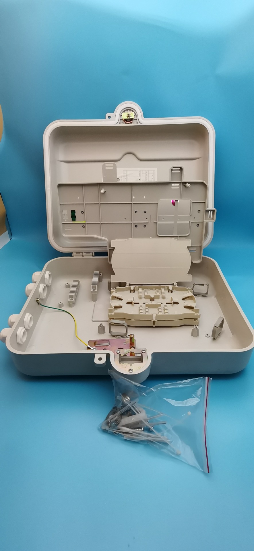
48 port wall mount termination box
SPECIFICATIONS:
Material : Mild Steel/Aluminum with 7 Tank Process powder coating.
Dimensions : 350*300*110 mm (H*W*D)
Color : RAL 7035/Black
Weight : 1.8–2 kg
Splice Holder : FR grade ABC.
Splice Holder Dimension : 180*110*15 mm (L*W*H)
Cable Glands : Nylon with nitrile butadiene rubber, cable diameter of 5mm to 14mm max available
Fiber components standard : Telecordia GR 326
Insertion Loss : less <.3dB (Multimode), < .2dB (Singlemode)
Plug/Unplug durability : 1000 times
#storing fiber terminations. It is also used for Indoor/Outdoor application and medium size multi-dwelling units (MDU’s) for FTTx.#Our IP rated wall mount fiber optic patch panel integrates three main functions of fiber splicing#cable winding & storing#and interface management. The enclosure adopts good quality metal sheets & surface electrostatic spray technique#which is offering safety & good endurance performance. It is the ideal design for building & campus networking.#48 port wall mount patch panel#terminator#cable#fiber optic#fiber optic product
0 notes
Text
#I'm Chinese business man Chinese manufacturer If you need anything#please tell us#we have the right price and high quality products#as well as excellent service#Contact Information:#whatsapp: https://wa.me/+8613123606387 https://zjbcfiberftth.com#✅Skype: 8613123606387 Port: Ningbo#China Production Capacity:10000 Piece/Pieces Per Week Payment Terms: T/T#Paypal#Money Gramfiber optic patch panel sc#black box fiber optic patch panel#panduit fiber optic patch panel#fiber optic patch panel 48 port#ortronics fiber optic patch panel#wall mounted fiber optic patch panel#rack mount fiber optic patch panel#fiber optic patch panel termination#48 port fiber optic patch panel price#din rail mount fiber optic patch panel#fiber optic patch panel enclosure#din rail fiber optic patch panel#fiber optic patch panel visio stencil download#fiber optic patch panel visio stencils#fiber optic patch panel wiki#fiber optic cable patch panel#fiber optic patch panel installation#19 fiber optic patch panel#24 port fiber optic patch panel price#tyco fiber optic patch panel#fiber optic patch panel din rail mounted
1 note
·
View note
Text
Picking Fiber Optic Patch Panels

When conquering inconvenience rises, an optic fiber specialist should pick the most reasonable patch board for a specific circumstance. That expert should perceive that with regards to simple establishment, legitimate end and long haul support, not all patch panels are made similarly. Optic fiber is vigorous and accordingly merits some unique treatment. For instance: if a flat copper link is harmed, one client will be influenced. On the off chance that a spine fiber goes down, it's anything but a ton of clients down with it. This is the reason utilizing completely encased interfacing equipment for optic fiber is critical. This is the place where the professional should pick between utilizing divider mounted or rack-mounted equipment. The optic fiber thickness required will in all probability impact the experts decision between the divider mounted and rack-mounted availability. Numerous professionals will decide to utilize fiber patch links. Trust your specialist to understand what's ideal.
Divider mounted nooks are reasonable for up to 24 optic strands, in spite of the fact that with little structure variables and high thickness connectors, can broaden the fiber optic link consider to numerous as 144. Divider mount fenced in areas additionally offer the advantage of decreased floor space prerequisites. Rack-mounted optic fiber walled in areas can be utilized with higher texture tallies or relying upon the vicinity to correspondences gear, where rack-mounted optic fiber nooks are ideal. 1U fenced in areas can deal with up to 24 optic fiber links with ST or SC connectors, or up to 48 optic strands by utilizing little structure factor connectors. For additional security, 2U to 4U walled in areas can be utilized to deal with up to 144 optic fiber associations.
A 12 fiber MPO connector can speed establishment time and increment the convergence of association equipment. The industrial facility ended and tried tapes deal with breaking out the optic filaments from the MPO connectors to ST, SC, or MT-RJ connectors. The MPO tapes can twofold the focus that are conceivable in rack-mount nooks - up to 72 optic strands in a 1U walled in area and 288 optic filaments in a 4U walled in area - making these optic filaments consummately fit to meet high thickness applications, for example, server farm's and capacity region organizations.
Openness is a worry for long haul support while picking a rack-mount nook. The 1U walled in areas may have an entrance board to arrive at the back optic strands, while bigger nooks may have a removable back cover with sufficient space inside to make changes or perform fixes. Strain alleviation and circle the executives for approaching links should be given, regardless administration gadgets ought to be little enough as to not meddle with admittance to the optic strands. Link the board for patch lines ought to be given on the facade of the walled in area with clear intro pages and marking masterminded to ease moves, adds and changes and by guaranteeing that port distinguishing proof isn't darkened by patch ropes. find more information Access Panels UK
Since copper patch panels should be sufficient not to flex a lot as the links are punched down. The moved edges on the board sheet metal stock assistance to make the panels inflexible. Copper patch panels ought to give 24 ports in a 1U stature or 48 ports in a 2U tallness. Ensure that the secluded jacks and circuit follows on the panels are shielded from trash that can short out circuits. All link the executives frameworks should be not difficult to utilize and keep up with to stay away from any expected issues.
1 note
·
View note
Text
Tips for Selecting Fiber Optic Patch Panels
For a particular situation, an optic fiber technician must choose the most suitable patch panel when surmounting trouble rises. Not all patch panels are created equally, that technician must recognize that long term maintenance and proper termination is required when it comes to easy installation.

Therefore, some special treatment is deserved by the Robust Optic fiber. For example, one user will be affected if a horizontal copper cable is damaged. It can take a lot of users down with it if a backbone fiber goes down. QSFP TO LC is much in demand.
For optic fiber is crucial, this is why using fully enclosed connecting hardware. Between using rack-mounted or wall-mounted hardware, the technician must choose.
Between the rack-mounted and wall-mounted connectivity, the optic fiber density required will most likely influence the technician’s choice. Using fiber patch cables will be preferred by many technicians. To know what's best, you must trust your technician.
When choosing a rack-mount enclosure, Accessibility is a concern for long term maintenance. To reach the rear optic fibers, the 1U enclosures may have an access panel while with adequate room inside, larger enclosures may have a removable rear cover to perform repairs or make changes. QSFP TO SFP is very popular in fiber optics.
As to not interfere with access to the optic fibers, nonetheless, management devices should be small enough, strain loop and relief management for incoming cables must be provided.

On the front of the enclosure, Cable management for patch cords should be provided with clear labeling and front covers arranged to changes, adds and ease moves by ensuring that port identification is not obscured by patch cords and QSFP TO QSFP.
Not to flex too much as the cables are punched down since copper patch panels need to be strong enough. To make the panels rigid, the rolled edges on the panel sheet metal stock help. In a 1U height or 48 ports in a 2U height, Copper patch panels should provide 24 ports.
To ensure that the circuit traces and modular jacks on the panels, it’s very crucial that they are protected from debris that can short out circuits. All cable management systems must maintain to avoid any potential problems and be easy to use.
4 notes
·
View notes
Text
What is an Optical Fiber Distribution Box?
What is an Optical Fiber Distribution Box?
Today, as the demand for higher data rates keeps increasing, optical fiber cables have been replaced with copper cables in FTTH(fiber to the home), FTTB(fiber to the building), and FTTC (fiber to the curb) networks. Optical fiber distribution boxes play a vital role in these wiring systems and thus are widely used in these cabling systems.
What is an optical fiber distribution box?
The optical fiber distribution box, also called the optical fiber distribution unit, optical fiber termination box, or optical fiber distribution point, is the intermediate node between the feeder cable of the distribution system and the bow-type drop cable leading to individual subscribers.
What’s the function of a fiber distribution box?
Used as a termination point, it links feeder cable to drop cable, integrating functions like fiber fixation, direct splicing, branching, straight-through, splitting, fiber termination, storage, solid protection, and better cable management in one unit; thus, it acts as a high-density fiber distribution box.
What’s the structure of the fiber distribution box?
Similar to ODFs, or fiber patch panels, fiber optic distribution box usually consist of appropriate space allowing for minimum bending radius, a bunch of fiber splice trays, fiber optic adapters, fiber optic splitters, fiber optic pigtails, several entrances, and exit ports, often made of PC-ABS materials with IP rating no less than IP65 and equipped with locking mechanism against theft or sabotage.
Typically, they’re lightweight and compact. The exit ports are much smaller than the entrance ports, as they’re used for connecting the pigtails or patch cords from the end-users.
ypes of fiber distribution boxes
Fiber distribution boxes can be classified in terms of different standards. Generally speaking, we can divide them by mount type, cores, and integrity.
By mount type
There’re various mounting types of fiber distribution boxes. The most common mount type is the wall mount, while the pole mount is an alternative. The wall mount is preferred by FTTB, while FTTC prefers the pole mount.
By exit ports
According to the number of exit ports a fiber distribution box contains, we can name it as the corresponding cores distribution box, for instance, a fiber distribution box having 8 exit ports can be called as an 8-core distribution box. There’re 2-,4-,6-,8-,12-,16-,24-,36-,48-core and more distribution boxes. Among them, the 8- and 16-core types are the most common.
As a professional fiber optic equipment suppliers in China, Yingda offers the best fiber optic distribution box for wordlwide customers. Welcome to inquire about wholesale fiber distribution box price, we are the best choice of optical distribution box manufacturers.
1 note
·
View note
Video
undefined
tumblr
1 in 4 out Hot Sell Heat shrinkable sealing 48 96 144Core FTTH Dome type Vertical fiber optic splice joint box terminal closure Made in China
Contact Details:
☎ + 86 15258160455(Whatsapp/Wechat)
🌐 https://zjbcfiberftth.com/
📧 Email: [email protected]
✅Skype: 86 15258160455
---------------------
1 in 4 out Hot Sell Heat shrinkable sealing 48 96 144Core FTTH Dome type Vertical fiber optic splice joint box terminal closure Made in China
Port: Ningbo, China
Production Capacity: 5000000
Payment Terms: S/C, T/T, D/P
Product Name:fiber optic splice joint box terminal closure
structure:Heat shrinkable sealing
Material:PP+GF
Dimension (mm):550mm(h)*155mm(d)
Max Capacity:144core
Maximum install tray Number:6
Ports:1 inlet 4 outlet
Fiber Terminal Box||fiber optic terminal box price|FTTH Fiber Optic Termination Box|fiber terminal box|wifi|Optical Fiber box|fiber access terminal box|optical termination|fiber optic terminal box hs code|Fiber Distribution Box Price|24 port|Fiber access terminal box|rack mount|Indoor fiber termination box|Fiber Box Price|indoor|Fiber Optic termination Box Rack mount|Optical termination box|fiber optical terminal box|fiber optic terminal box|FTTH Termination Box|fiber optic splitter terminal box|24 Port Fiber termination box|fiber terminal box price|fiber optik terminal box|ftth termination|optic termination|ftth fiber optic terminal box|Fiber box WiFi|optical|Fiber Connection Box|access|fiber optic cable terminal box|Fiber termination Box Wall Mount|Outdoor Fiber Termination box|termination|fiber terminal box hs code
Optical Distribution Boxes||Fiber Termination Box price|ftth|fiber|optical distribution box|Fiber termination box|ODF fiber|fiber termination box|Fiber distribution Box|Fiber Distribution Box Price|point|fiber box price|Fiber OPTIC DISTRIBUTION BOX HS code|box|Fiber Box Price|box price|FIBER DISTRIBUTION BOX hs code|Optical fiber distribution box|frame|fiber optic|Fiber Optic Distribution Box Price|Optical distribution frame|ODB|Fibre Junction box|FTTH Distribution Box
fiber termination box wall mount ||patch panel|Fiber termination Patch Panel|Fiber Optic Junction Box|Fiber Optic Wall Mount Termination Box|6-port wall mount fiber patch panel|fiber optic wall mount termination box|Fiber Patch panel|Panduit Wall Mount Fiber Enclosure|optic junction|fiber termination box wall mount|Fiber Optic termination Box Rack mount|optic|Fiber Optic Wall Mount Enclosure|Outdoor Wall mount fiber Enclosure|rack|patch|Fiber Patch Box|commscope|enclosure|CommScope wall Mount Fiber Enclosure|Fiber tray Rack Mount|Fiber patch panel Box|outdoor|Fiber optic outlet box
Fiber Optic Wall Mount Termination Boxes||patch panel|350 ft fiber optic cable|Fiber Optic Junction Box|Fiber Optic Box|Fiber optic cable assemblies|Fiber Termination Panel|6-port wall mount fiber patch panel|Fiber Optic panel Box|junction box|box|outlet box|Fiber Optic termination Box Rack mount|Heavy Duty Fiber Optic Cable|panduit|Fiber optic Splice box outdoor|6-port|Fiber Patch Box|enclosure|Fiber patch panel Box|Fiber termination Box Wall Mount|outdoor|box rack|Fiber optic outlet box
fiber optic termination box||ftth|FTTH Fiber Optic Termination Box|Fibre termination box|fiber optic termination box in usa|wifi|fiber optic termination box|fiber optic termination box price india|Fiber optic Box outdoor|Fiber Distribution Box Price|fiber optic termination box suppliers|wall mount fiber optic termination box|rack mount|Indoor fiber termination box|indoor|Fiber terminal box|Fiber Optic termination Box Rack mount|wall mount|fiber optic termination boxes|FTTH Termination Box|24 Port Fiber termination box|corning fiber optic termination box|Fiber box WiFi|fiber optic termination box hs code|optical|fiber optic termination box rack mount|fiber optic termination box plastic|Fiber optic distribution box|Fiber termination Box Wall Mount|outdoor|fiber optic termination box price|Outdoor Fiber Termination box|Optical Fiber box
optical fiber cable distribution box ||Fiber Termination Box price|ftth|Fiber termination box|wifi|price|Indoor fiber termination box|Fiber Box Price|Fiber optic cable junction box|junction|Outdoor Fiber Termination box|optic|Optical fiber distribution box|Fiber Optic Distribution Box Price|Fiber box WiFi|Fibre Junction box|optical fiber cable distribution box|FTTH Distribution Box|Optical distribution box|Fiber box pldt|termination|Optical Fiber box
Optical Fiber Distribution Box ||Fiber Termination Box price|ftth|Fiber termination box|wifi|Fiber Distribution Point|Fiber distribution cabinet|Fiber distribution Box|Fiber Distribution Box Price|price|Fiber Box Price|FIBER DISTRIBUTION BOX hs code|optic|optical fiber distribution box|cabinet|Fiber Optic Distribution Box Price|Fiber box WiFi|Syrotech|optical fiber distribution box hs code|optical fiber cable distribution box|FTTH Distribution Box|Optical distribution box|termination
0 notes
Video
undefined
tumblr
Contact Details:
☎ + whatsapp: https://wa.me/+8613123606387
🌐 https://zjbcfiberftth.com/
📧 Email: [email protected]
✅Skype: 8613123606387
https://youtu.be/bIdpzdEC1WU
https://www.tiktok.com/@beyondlovexy/video/7074985094825479467
---------------------
SC/UPC --SC/APC
Production Capacity: 5000000pieces/Year
Payment Terms: L/C, T/T, Western Union, Paypal
Application: Communication
Type: Fiber Optic Patch Panel
Connection Structure: MTP/MPO
Material Shape: Flat
Allowed Lateral Pressure: more than 1000(N/100mm)
Allowed Tensile Strength: 100N Less than 1000N
______________________________________________________
fiber optic patch panel , fiber optic patch panel wiring diagram,fiber optic patch panel rack mount , rack mounted fiber optic patch panel,patch panel fiber optic , fiber optic patch panel corning,corning fiber optic patch panel , leviton fiber optic patch panel,24 port fiber optic patch panel , fiber optic patch panel 24 port,fiber optic patch panel 12 port , fiber optic patch panel wall mount,12 port fiber optic patch panel ,fiber optic patch panel manufacturers , wall mount fiber optic patch panel,corning 12 port fiber optic patch panel , fiber optic lc patch panel,siemens fiber optic patch panel , fiber optic wall mount patch panel,96 port fiber optic patch panel , how to connect fiber optic cable to patch panel,odf fiber optic patch panel , fiber optic patch panel function,fiber optic patch panel sc , black box fiber optic patch panel,panduit fiber optic patch panel , fiber optic patch panel 48 port,ortronics fiber optic patch panel , wall mounted fiber optic patch panel,rack mount fiber optic patch panel , fiber optic patch panel termination,48 port fiber optic patch panel price , din rail mount fiber optic patch panel,fiber optic patch panel enclosure , din rail fiber optic patch panel,fiber optic patch panel visio stencil download, fiber optic patch panel visio stencils,fiber optic patch panel wiki , fiber optic cable patch panel,fiber optic patch panel installation , 19 fiber optic patch panel,24 port fiber optic patch panel price , tyco fiber optic patch panel,fiber optic patch panel din rail mounted , fiber optic patch panel price,patch panel for fiber optic cables , patch panel fiber optic 24 port,siecor fiber optic patch panel , fiber optic patch panel visio stencil,fiber optic patch panel wiring diagram,fiber optic patch panel rack mount , rack mounted fiber optic patch panel,patch panel fiber optic , fiber optic patch panel corning,corning fiber optic patch panel , leviton fiber optic patch panel,24 port fiber optic patch panel
0 notes
Text
12U Wall Mount Cabinet Recommendation
12U Wall Mount Cabinet Recommendation
Nowadays, cabinets play an important role in the data center because they can be used to achieve high-density cabling and improve efficiency of data center network management and operation. According to different applications, cabinets can be divided into sever cabinets and network cabinets. Server/network cabinets are generally divided into two types. There are floor cabinet and wall mount cabinet. As for wall mount cabinet, 6U,9U, or 12U types are commonly seen in the market. This post will focus on two types of 12U wall mount cabinets, some detailed information about them will be elaborated below.
12U Wall Mount Cabinet Overview
For 12U, the “U” stands for the rack unit that is an EIA standard measuring unit for rack mount type equipment. 1U is equal to 1.75″ in height. A 12U wall cabinet means it would have 21″ internal usable space (12×1.75″). As for wall mount cabinet, it is designed to be attached to the wall so as to save spaces. The 12U wall mount cabinet uses a small and compact design, which can be placed on desks or mounted on walls in classroom, retail store or office for storing equipment and saving floor space. Here set two series of 12U wall mount cabinet from FS as examples.
12U GV600-Series Wall Mount Cabinet

With an arc hexagonal perforated front doors and doors on side panels, massive ventilation for servers and network equipment can be guaranteed. In addition, the rear door is equipped with a strong hinge system, which can make back-door access much easier to run new cabling, replace some equipment parts and so on. As for providing weight capacity for your heaviest equipment, this 12U GV600-Series wall mount cabinet uses SPCC material and supports a total load capacity of up to 198.4lbs (90kg). For simple and sturdy mounting, the rack’s mounting holes are positioned 16 inch, so you can securely attach it to wall studs. In terms of cable routing, it has convenient top and bottom ports, which can help cable routing more easier. Because it has massive ventilation, so it can make equipment cool.
12U GW600-Series Wall Mount Cabinet

Usually, 12U GW600-series wall mount cabinet has one glass front door that can be open, closed or locked to keep the inside networking equipment safe and protect the equipment against dust or water. In most cases, this12U cabinet will be installed on the wall with the door facing outward, and the equipment facing the door for easier access. The door can be locked for protecting the equipment against dust or water. As for providing weight capacity for your heaviest equipment, this cabinet also uses SPCC material and supports a total load capacity of up to 132.3lbs (60kg). For simple and sturdy mounting, the rack’s mounting holes are positioned 19.21 inch, so you can securely attach it to wall studs. Comparing with another cabinet mentioned above, this cabinet is a more cost-effective cabinet because it can protect equipment from dust and other hazards. And it can be used in open, unprotected spaces such as warehouses, retail facilities and schools.
Application Scenario
As we mentioned above, the FS 12U cabinet comes with two series. In the following part, we will illustrate how they are applied in different scenarios. The12U GV600-series wall mount cabinet is commonly used in back officies, classrooms and telecom rooms. And 12U GW600-series wall mount cabinet is widely applied in back officies, factories, retail stores.
When you use12U GV600-series wall mount cabinet, the following products are suggested:
1U 24 Ports Cat6 Unshielded Feed-Through High Quality Patch Panel
1U Plastic Single Sided Horizontal Cable Manager with Finger Duct
Single-Phase 15A/250V Basic PDU, 8 IEC320 C13 Outlets, CEE7 Plug, 6.6ft Cord, 1U Rack-Mount.
6in (0.15m) Cat6 Snagless Unshielded (UTP) PVC CM Slim Ethernet Network Patch Cable, Blue
1U 19” Vented Cantilever Fixed Shelf
When you use 12U GW600-series wall mount cabinet, the following products are suggested:
S3900-48T4S 48-Port 10/100/1000BASE-T Gigabit Stackable Managed Switch with 4 10Gb SFP+ Uplinks
1U 24 Ports Cat6 Unshielded Feed-Through High Quality Patch Panel
1U Plastic Single Sided Horizontal Cable Manager with Finger Duct
6in (0.15m) Cat6 Snagless Unshielded (UTP) PVC CM Slim Ethernet Network Patch Cable, Blue
1U 19” Vented Cantilever Fixed Shelf
Conclusion
12U wall mount cabinets will be more effective for individuals and small businesses. We tailor these two types of 12U wall mount cabinets for you and hope you can have a deeper understanding about features and applications of them. FS provides 12U wall mount cabinets at competitive prices. If you still have any questions about wall mount cabinets, feel free to contact us at [email protected].
0 notes
Text
Computer Network Cabling
Network Cabling and Installation https://www.itccablingandcameras.com/
Have you ever wondered what it is that connects computers and networks to one another? Network cable in conjunction with the associated hardware (network switches, hubs, demarcation equipment) is responsible for computers being able to connect and transfer data across intranets (internal network) and the internet. Network cabling today is used for many other purposes besides computer networking. It can be used to carry video for security camera systems as well as video for cable TV and AV (Audio/Visual) applications. Network cabling is also used as control cable in Building Maintenance Systems and Access Control Systems. There are several different types of cables that are used for this purpose, including unshielded twisted pair, shielded twisted pair, fiber optic and coaxial. In some cases, only one type of cable is used in a network, while in other cases, many different types are used. Wireless systems are becoming more and more popular but always remember you still need network cabling for the wireless system. There is still two things that make network cabling better than a wireless network: it is much more secure and reliable.
Understanding Cable Type
Before you can really understand how cable networking works, you need to know about the various cables and how they work. Each cable is different, and the type of cable used for a particular network needs to be related to the size, topology and protocol of the network. Here is a rundown of the cables that are most commonly used for network cabling:
Unshielded/Shielded Twisted Pair - This is the type of cable that is used for many Ethernet networks. There are four sets of pairs of wires inside the cable. There is a thick plastic separator that keeps each pair isolated through the run of cable. Each pair of wires are twisted so there will be no interference from other devices that are on the same network. The pairs are also twisted at different intervals so they will not cause interference between themselves. In an application where there is a lot of Electromagnetic Interference (EMI), such as a mechanical space, you may choose to use shielded twisted pair, which has an outer shielding that adds extra protection from EMI. Category 5e, 6, 6A and 7 are the general choices today. Twisted pair cable is limited to 295' on a horizontal run. Twisted pair cable is used for many applications. Standard station cabling for computers and VOIP phones, wireless access points, network cameras, access control and building maintenance systems are just a few. This is one of the most reliable types of cables, and when used, network failures are less common than when other cables are used.
Fiber Optic - Fiber optic cable is primarily used as backbone cable although it is being used more and more as station cable (think FIOS). By backbone cable I mean it connects Telecommunication Rooms within a space to each other. Fiber optic cable has huge broadband capacities which allow it to carry large amounts of information as super fast speeds. Fiber cables can cover great distances(hundreds of meters) as opposed to copper cable. Because these cables must work so hard and the information travels such distances, there are many layers of protective coating on fiber optic cables. Fiber cables transmit light as opposed to electrical current. Fiber optic cable requires much less power than high speed copper does. Fiber optic cable is a great choice for high speed reliable communications.
Coaxial Cable - Coaxial cable usually falls under the scope of work of the network cabling installation contractor. Coax will be used for the cable television locations within the space you are cabling. The service provider will drop off the outdoor cable at the point of entry. The contractor will run an extension (usually RG-11) to the local telecom closet within the space. The individual station runs(RG-6) will terminate on a splitter to connect to the service cable. The center of this type of cable has a copper conductor and a plastic coating that acts as an insulator between the conductor and the metal shield. This cable is covered with coating, which can vary in thickness. The thicker the coating, the less flexible it is going to be. There are a few types of terminations for coax. Compression, crimp and twist on are the three types of terminations. The best method is compression as long as they are performed correctly. Crimp terminations are also reliable and require the right tool for the particular connector you are using. I would not recommend twist on as they are not reliable and prone to problems. A few types of coax connectors are F connectors, BNC connectors and RCA connector.
Network Cabling Components
Patch panel - This is the panel where all of the station cables terminate within the Telecommunications Room. They are usually mounted on a wall mount or floor mount telecommunications rack. Typically there are 24, 48 or 72 ports on a patch panel. There are a few different styles such as angled or straight. Panels also have the option of having the 110 type pins attached to the back of the panel or you can terminate jacks and snap them into the empty panel.
Data Jack - This is the connector where each individual cable is terminated out at the station side. The jacks are snapped into a faceplate ranging from 1 to 8 ports typically. Data jacks can be terminated in a 568A or 568B pinout. Check with the customer or designer for the correct pinout.
RJ 45 Connector - The RJ-45 connector is installed on the end of a network cable. They are 8 pin connectors. The most common place to find the RJ 45 is on a cable terminating at a wireless access point. The RJ 45 is a male connector and would plug into the port on the WAP.
Wireless Access Points - These are devices that transmit network access wirelessly. Typically they are mounted on the ceiling or wall. A wireless survey would need to be performed to maximize the correct placement of WAP's. Contrary to popular belief wireless devices STILL need to be fed with network cabling.
Cable Supports - (Commonly called J-Hooks) Cable supports are mounted in the ceiling as a support structure for your cable bundles. Main path cable supports should be mounted to the concrete deck ceiling within the space. You are no longer permitted to hang j-hooks from ceiling supports, electrical or plumbing pipe or any other system infrastructure.
Wire Managers - Wire managers are installed between patch panels and switches to manage patch cables. They serve a very important purpose as they keep law and order in a Telecommunications Room. Nothing irks me more than finishing a brand new beautiful install and having the IT group come in and not use the wire managers. It ruins the aesthetics of the job. In addition it sets a bad precedence from the birth of the Telecommunications Room that others are sure to follow.
Firestop Sleeves - Firestop sleeves are a vital part of any network cabling installation these days. Gone are the days of just banging holes into sheetrock and passing cables through. When you penetrate any firewall on a job you must install a firestop sleeve. There are specific products made for this. EZ Path and Hilti both make excellent versions in varying sizes. You can install a sleeve of EMT pipe through a wall also as long as you use firestop putty or firestop silicone to seal off all openings. This can save lives and minimize damage in the event of a fire.
Cable Labels - All cables and termination points should have a unique label. This makes installation, maintenance and troubleshooting much simpler. For a professional all labels should be computer generated. Hand written labels are just not acceptable today.
Network Cabling Installation
Network cabling installation drawings should be designed by a BICSI certified RCDD (Registered Communication Distribution Designer). There are a few things that need to be considered.
The type of cabling solution to be implemented - The cabling vendor or customer will need to select a solutions manufacturer. Siemon, Leviton, Ortronics and Panduit are some of the more common choices. The type of cabling solution will need to be discussed. Cat 5e, Cat 6, Cat 6A or Cat 7 are the copper types of network cables that can be offered. The style of the racks, data jacks, faceplates, patch panels and wire managers will also need to be discussed and chosen. Make sure this is done early as lead times can be long for certain manufactures and styles.
The location of the network equipment and racks - The room where they are housed is commonly referred to as MDF (Main Distribution Frame) Data Room, Telco Room or Telecommunications Room. All cables runs need to be within 100 meters. If cable runs are going to be over 100 meters you will need to add a second Telecommunications Room. This is also called an IDF(intermediate Distribution Frame). The IDF will often need to be connected to the MDF via fiber optic backbone cabling. The MDF will house the service provider feed from the street, which will feed the network. Typically you will also find security equipment and access control equipment here. It is a better design to have all the low voltage systems housed in one location. Measure all equipment and racks that will be required based on cabling quantities. Include access control, security, electrical panels and air conditioning units. The room needs to be large enough to accommodate all equipment.
The pathways of the cable trunks above the ceilings - Cable paths need to steer clear of electrical light fixtures or other sources of EMI (Electro Magnetic Interference). Keep cable paths in accessible areas of the ceiling for future cable runs and ease of maintenance. All paths should be run above hallways or corridors and cables enter individual rooms on sweeping 90 degree turns. Install a firestop sleeve or putty for all penetrations of a fire wall. Be careful when pulling cables so as not to bend them beyond their bend radius. This will cause a failure when testing. DO NOT tie cables to ceiling hangers or sprinkler pipes. They need to be tied at least every 5' on horizontal runs, and even more on vertical runs. J-hook supports should be anchored to the concrete deck above. Use velcro wraps every 5' or so when finished running cable to give your cable bundles a great looking finish.
Terminating Network Cabling - When terminating cable make sure to check the floor-plan numbering to each cable label to make sure the cables are in the correct spot. If something is not matching leave that cable on the side to be "toned out" later on. Use a cable stripping & cutting tool to get a uniform cut on the cable jacket and to be sure you won't nick the copper conductors inside. Always keep each pair twisted as tight as possible right up to the pins where you terminate the cable. This will ensure you won't get a NEXT or Return Loss failure. Before you start any terminations inquire weather the pinout will be 568A or 568B. This will determine which order the conductors are terminated in and is very important before you start. All cables should be dressed nicely and uniform. The project manager should make a termination chart of the patch panels for the technician that will perform the terminations. This will show the back of the patch panels and where each cable gets terminated with it's label number.
Testing your network cabling - There are a number of cabling testers out on the market. The tester we prefer to use is the Fluke DTX-1800 Cable Analyzer. This is an amazing tool. It will give you a detailed report of each cable that is tested. It tests for wiremap, insertion loss, NEXT, PSNEXT, ACR-N, Insertion Loss and many others. The best part about these new age testers is their troubleshooting skills. The Fluke will tell you where a cable is damaged and which particular conductor is damaged. If you terminated a pair out of sequence the tester will tell you which pair and on what end the error was made. The Fluke does everything but fix it for you! Most clients want to see verified test results. The new testers will provide cleaned up PDF files of the test results. These can be emailed directly to the client.
Hopefully this guide has helped you to better understand the complete system of network cabling. It is an ever changing field and we need to keep up on the latest technology to stay ahead of the curve and offer our clients the best cabling solutions. Please add your comments, suggestions or questions. Please sign up to our email list for the latest cabling news and our shared experiences from the field. You will also receive special offers on future training products before they are released. Thanks for your support.
Please visit http://www.networkcablingworld.com, the premier website for network cabling installation solutions, cabling tool and equipment reviews, free advice and a wealth of experience at your fingertips.
Article Source: http://EzineArticles.com/expert/Michael_Stones/1110019
https://www.itccablingandcameras.com/
Article Source: http://EzineArticles.com/6716965
0 notes
Text
How To Use A Fiber Optic Patch Panel
What Is a Fiber Optic Patch Panel?
Patch panel is defined as the interface between multiple optical fibers and optical equipment. It’s a termination unit that helps networking and fiber distribution from wiring closet to various terminal equipment. Fiber optic patch panel is a mounted hardware unit containing an assembly of port locations in a communication or other electronic or electrical system. Fiber optic patch panel is used to terminate the fiber optic cable and provide access to the cable’s individual fibers for cross connection. They are mostly mounted in 19 inch relay racks, but they can also be mounted on freestanding rails, in cabinets and also on walls.
Fiber Optic Patch Panel Types
Fiber optic atch panel are divided into two types based on different designs, the wall mount and rack mount category. Both types can house, organize, and protect fiber optic cable and connectors. Rack mount patch panels come in flat and angled versions while the wall mount patch panel is used for direct termination of several fibers, and are mostly equipped with routing guides to limit the bend radius for enhanced strain-relief control. They can also be classified according to the count of ports. The common patch panels are come in 12 ports, 24 ports, 48 ports and 96 ports. The height of it can also vary as 1U, 2U, 3U and so on. For more about the types, click here.
How to Connect Fiber Optic Cable To Fiber Patch Panel
Insert the adapters into the mounting plate, then fix the mounting plate in position. Prepare cables based on standard termination procedures and ensure there is enough surplus cable to work with. Connect the cable by fixing the gland and roll the excess fiber onto the spool. After that, remove the protection cap and insert into position in the adapter. Once the cables are all attached, it’s better to use a zip tie to secure the cables in a bundle. In a typical setup, the connection consists of a shorter cable plugged into the front side of the patch panel and a longer cable plugged into the back. In this way, the panel can take the place of otherwise expensive switching equipment. This is the extract from How to Connect Fiber Optic Cable to Fiber Optic Patch Panel . You can find more useful information in it.
How To Use A Fiber Optic Patch Panel
Getting a fiber optic patch panel is mainly for two reasons: termination and better cable management. As for patch panel termination, it is the step to terminate fibers on the patch panel, a precise task required much attention. As for cable management, here I recommend you to accompany it with cable managers. From a top-down perspective, the order of the devices in a cabinet should be: fiber patch panel 1, cable manager 1, fiber patch panel 2, cable manager 2 For fiber optic cabling cable management, you should plan the location of your fiber connectivity hardware carefully, including fiber patch panels. You can choose between direct cross connection and patch panel. It is also necessary to arrange your routing and dressing of your fiber patch cords if you choose to use fiber panels. In the meantime, you also have a choice to use fiber cable management brackets to avoid the dangling fiber patch cables. Owning a fiber optic path will not only spare you a lot of time and energy in cabling design, but also present you a neat cabling system, which will bring you efficient work.
Related Article: What Can High-density Fiber Patch Panel Achieve?
How to Use Fiber Patch Panel for Better Cable Management
0 notes
Text
Ultimate Home LAB Set Up With Sean Hogston
Sean Hogston shares his approach he’s used to create his ultimate home Lab.
Use a T-Bar horizontally for multiple AP mounting
Take a 1×2 piece of wood, route the back edge across so you can lay a t-bar horizontally on that 1×2 and then mount the whole thing on the wall. What you end up with is a row with an many APs as can fit.
Of course not all to be fired up at the same time, but this allows you to have easy access to test any AP at any given time.
For APs that are too heavy or don’t allow for T-Bar mounting you can add a 1×8 to the wall as a secondary mounting row.
Run everything to a single patch panel
From the mounting brackets all the APs run behind to a single 48 port patch panel, keeping all cables up off the floor and out of the way. This way everything is patched all the time to the patch panel and then you just patch down from the patch panel to some type of switching environment.
Don’t forget the wired side. Make sure that you’ve got a couple different examples of the switching sides so that you can account for different testing that you’re doing especially if you plan on installing multiple vendors equipment.
Reduce the chaos with totes & shelving
It’s important to keep things clean and out of the way – especially if you’re taking over any part of your house for your lab. Wired shelving to keep things open works great and see through totes is a must to be able to quickly and easily see and remember what you have stored where.
Run cables over the doors
If you have cables that have to pass by a door opening you can buy little hooks from the garage section at Lowe’s or Home Depot and put them on each side of the door. This allows the longer cables to actually droop up and over onto the other side of the door and keeps your cable much more organized.
Divide your rack for home and testing
You can divide your racks into two sides. Any equipment that stays on to run
the house Network is is on the left side. All test gear on goes on the right side. That way the test gear is on only when it’s needed.
Remote power is your friend
Finally, remember that remote power strips are your friend. Everything’s on a remote power strip so that you can turn it on and off from anywhere.
Watch Sean’s full presentation on his ultimate lab set up here
The post Ultimate Home LAB Set Up With Sean Hogston appeared first on Wireless LAN Professionals.
from James Dole Gadgets News http://www.wlanpros.com/ultimate-home-lab-set-sean-hogston/
0 notes
Text
Ultimate Home LAB Set Up With Sean Hogston
Sean Hogston shares his approach he’s used to create his ultimate home Lab.
Use a T-Bar horizontally for multiple AP mounting
Take a 1×2 piece of wood, route the back edge across so you can lay a t-bar horizontally on that 1×2 and then mount the whole thing on the wall. What you end up with is a row with an many APs as can fit.
Of course not all to be fired up at the same time, but this allows you to have easy access to test any AP at any given time.
For APs that are too heavy or don’t allow for T-Bar mounting you can add a 1×8 to the wall as a secondary mounting row.
Run everything to a single patch panel
From the mounting brackets all the APs run behind to a single 48 port patch panel, keeping all cables up off the floor and out of the way. This way everything is patched all the time to the patch panel and then you just patch down from the patch panel to some type of switching environment.
Don’t forget the wired side. Make sure that you’ve got a couple different examples of the switching sides so that you can account for different testing that you’re doing especially if you plan on installing multiple vendors equipment.
Reduce the chaos with totes & shelving
It’s important to keep things clean and out of the way – especially if you’re taking over any part of your house for your lab. Wired shelving to keep things open works great and see through totes is a must to be able to quickly and easily see and remember what you have stored where.
Run cables over the doors
If you have cables that have to pass by a door opening you can buy little hooks from the garage section at Lowe’s or Home Depot and put them on each side of the door. This allows the longer cables to actually droop up and over onto the other side of the door and keeps your cable much more organized.
Divide your rack for home and testing
You can divide your racks into two sides. Any equipment that stays on to run
the house Network is is on the left side. All test gear on goes on the right side. That way the test gear is on only when it’s needed.
Remote power is your friend
Finally, remember that remote power strips are your friend. Everything’s on a remote power strip so that you can turn it on and off from anywhere.
Watch Sean’s full presentation on his ultimate lab set up here
The post Ultimate Home LAB Set Up With Sean Hogston appeared first on Wireless LAN Professionals.
from http://www.wlanpros.com/ultimate-home-lab-set-sean-hogston/
0 notes
Text
Ultimate Home LAB Set Up With Sean Hogston
Sean Hogston shares his approach he’s used to create his ultimate home Lab.
Use a T-Bar horizontally for multiple AP mounting
Take a 1×2 piece of wood, route the back edge across so you can lay a t-bar horizontally on that 1×2 and then mount the whole thing on the wall. What you end up with is a row with an many APs as can fit.
Of course not all to be fired up at the same time, but this allows you to have easy access to test any AP at any given time.
For APs that are too heavy or don’t allow for T-Bar mounting you can add a 1×8 to the wall as a secondary mounting row.
Run everything to a single patch panel
From the mounting brackets all the APs run behind to a single 48 port patch panel, keeping all cables up off the floor and out of the way. This way everything is patched all the time to the patch panel and then you just patch down from the patch panel to some type of switching environment.
Don’t forget the wired side. Make sure that you’ve got a couple different examples of the switching sides so that you can account for different testing that you’re doing especially if you plan on installing multiple vendors equipment.
Reduce the chaos with totes & shelving
It’s important to keep things clean and out of the way – especially if you’re taking over any part of your house for your lab. Wired shelving to keep things open works great and see through totes is a must to be able to quickly and easily see and remember what you have stored where.
Run cables over the doors
If you have cables that have to pass by a door opening you can buy little hooks from the garage section at Lowe’s or Home Depot and put them on each side of the door. This allows the longer cables to actually droop up and over onto the other side of the door and keeps your cable much more organized.
Divide your rack for home and testing
You can divide your racks into two sides. Any equipment that stays on to run
the house Network is is on the left side. All test gear on goes on the right side. That way the test gear is on only when it’s needed.
Remote power is your friend
Finally, remember that remote power strips are your friend. Everything’s on a remote power strip so that you can turn it on and off from anywhere.
Watch Sean’s full presentation on his ultimate lab set up here
The post Ultimate Home LAB Set Up With Sean Hogston appeared first on Wireless LAN Professionals.
from Computer And Technology http://www.wlanpros.com/ultimate-home-lab-set-sean-hogston/
0 notes
Text
Network Cabling and Installation
New Post has been published on https://myupdatesystems.com/2017/04/14/network-cabling-and-installation/
Network Cabling and Installation
Have you ever wondered what it is that connects computers and networks to one another? Network cable in conjunction with the associated hardware (network switches, hubs, demarcation equipment) is responsible for computers being able to connect and transfer data across intranets (internal network) and the internet. Network cabling today is used for many other purposes besides computer networking. It can be used to carry video for security camera systems as well as the video for cable TV and AV (Audio/Visual) applications. Network cabling is also used as control cable in Building Maintenance Systems and Access Control Systems. There are several different types of cables that are used for this purpose, including unshielded twisted pair, shielded twisted pair, fiber optic and coaxial. In some cases, only one type of cable is used in a network, while in other cases, many different types are used. Wireless systems are becoming more and more popular but always remember you still need network cabling for the wireless system. There is still two things that make network cabling better than a wireless network: it is much more secure and reliable.
Understanding Cable Type
Before you can really understand how cable networking works, you need to know about the various cables and how they work. Each cable is different, and the type of cable used for a particular network needs to be related to the size, topology, and protocol of the network. Here is a rundown of the cables that are most commonly used for network cabling:
Unshielded/Shielded Twisted Pair – This is the type of cable that is used for many Ethernet networks. There are four sets of pairs of wires inside the cable. There is a thick plastic separator that keeps each pair isolated through the run of cable. Each pair of wires is twisted so there will be no interference from other devices that are on the same network. The pairs are also twisted at different intervals so they will not cause interference between themselves. In an application where there is a lot of Electromagnetic Interference (EMI), such as a mechanical space, you may choose to use shielded twisted pair, which has an outer shielding that adds extra protection from EMI. Category 5e, 6, 6A and 7 are the general choices today. Twisted pair cable is limited to 295′ on a horizontal run. Twisted pair cable is used for many applications. Standard station cabling for computers and VOIP phones, wireless access points, network cameras, access control and building maintenance systems are just a few. This is one of the most reliable types of cables, and when used, network failures are less common than when other cables are used.
Fiber Optic – Fiber optic cable is primarily used as backbone cable although it is being used more and more as station cable (think FIOS). By backbone cable I mean it connects Telecommunication Rooms within a space to each other. Fiber optic cable has huge broadband capacities which allow it to carry large amounts of information as super fast speeds. Fiber cables can cover great distances(hundreds of meters) as opposed to copper cable. Because these cables must work so hard and the information travels such distances, there are many layers of protective coating on fiber optic cables. Fiber cables transmit light as opposed to electrical current. Fiber optic cable requires much less power than high-speed copper does. Fiber optic cable is a great choice for high-speed reliable communications.
Coaxial Cable – Coaxial cable usually falls under the scope of work of the network cabling installation contractor. Coax will be used for the cable television locations within the space you are cabling. The service provider will drop off the outdoor cable at the point of entry. The contractor will run an extension (usually RG-11) to the local telecom closet within the space. The individual station runs(RG-6) will terminate on a splitter to connect to the service cable. The center of this type of cable has a copper conductor and a plastic coating that acts as an insulator between the conductor and the metal shield. This cable is covered with the coating, which can vary in thickness. The thicker the coating, the less flexible it is going to be. There are a few types of terminations for coax. Compression, crimp and twist on are the three types of terminations. The best method is compression as long as they are performed correctly. Crimp terminations are also reliable and require the right tool for the particular connector you are using. I would not recommend twist on as they are not reliable and prone to problems. A few types of coax connectors are F connectors, BNC connectors, and RCA connector.
Network Cabling Components
Patch panel – This is the panel where all of the station cables terminate within the Telecommunications Room. They are usually mounted on a wall mount or floor mount telecommunications rack. Typically there are 24, 48 or 72 ports on a patch panel. There are a few different styles such as angled or straight. Panels also have the option of having the 110 type pins attached to the back of the panel or you can terminate jacks and snap them into the empty panel.
Data Jack – This is the connector where each individual cable is terminated out at the station side. The jacks are snapped into a faceplate ranging from 1 to 8 ports typically. Data jacks can be terminated in a 568A or 568B pinout. Check with the customer or designer for the correct pinout.
RJ 45 Connector – The RJ-45 connector is installed on the end of a network cable. They are 8 pin connectors. The most common place to find the RJ 45 is on a cable terminating at a wireless access point. The RJ 45 is a male connector and would plug into the port on the WAP.
Wireless Access Points – These are devices that transmit network access wirelessly. Typically they are mounted on the ceiling or wall. A wireless survey would need to be performed to maximize the correct placement of WAP’s. Contrary to popular belief wireless devices STILL need to be fed with network cabling.
Cable Supports – (Commonly called J-Hooks) Cable supports are mounted in the ceiling as a support structure for your cable bundles. Main path cable supports should be mounted to the concrete deck ceiling within the space. You are no longer permitted to hang j-hooks from ceiling supports, electrical or plumbing pipe or any other system infrastructure.
Wire Managers – Wire managers are installed between patch panels and switches to manage patch cables. They serve a very important purpose as they keep law and order in a Telecommunications Room. Nothing irks me more than finishing a brand new beautiful install and having the IT group come in and not use the wire managers. It ruins the aesthetics of the job. In addition, it sets a bad precedence from the birth of the Telecommunications Room that others are sure to follow.
Firestop Sleeves – Firestop sleeves are a vital part of any network cabling installation these days. Gone are the days of just banging holes into sheetrock and passing cables through. When you penetrate any firewall on a job you must install a firestop sleeve. There are specific products made for this. EZ Path and Hilti both make excellent versions in varying sizes. You can install a sleeve of EMT pipe through a wall also as long as you use firestop putty or firestop silicone to seal off all openings. This can save lives and minimize damage in the event of a fire.
Cable Labels – All cables and termination points should have a unique label. This makes installation, maintenance and troubleshooting much simpler. For a professional, all labels should be computer generated. Handwritten labels are just not acceptable today.
Network Cabling Installation
Network cabling installation drawings should be designed by a BICSI certified RCDD (Registered Communication Distribution Designer). There are a few things that need to be considered.
The type of cabling solution to be implemented – The cabling vendor or customer will need to select a solutions manufacturer. Siemon, Leviton, Ortronics and Panduit are some of the more common choices. The type of cabling solution will need to be discussed. Cat 5e, Cat 6, Cat 6A or Cat 7 are the copper types of network cables that can be offered. The style of the racks, data jacks, faceplates, patch panels and wire managers will also need to be discussed and chosen. Make sure this is done early as lead times can be long for certain manufacturers and styles.
The location of the network equipment and racks – The room where they are housed is commonly referred to as MDF (Main Distribution Frame) Data Room, Telco Room or Telecommunications Room. All cables run need to be within 100 meters. If cable runs are going to be over 100 meters you will need to add a second Telecommunications Room. This is also called an IDF(intermediate Distribution Frame). The IDF will often need to be connected to the MDF via fiber optic backbone cabling. The MDF will house the service provider feed from the street, which will feed the network. Typically you will also find security equipment and access control equipment here. It is a better design to have all the low voltage systems housed in one location. Measure all equipment and racks that will be required based on cabling quantities. Include access control, security, electrical panels and air conditioning units. The room needs to be large enough to accommodate all equipment.
The pathways of the cable trunks above the ceilings – Cable paths need to steer clear of electrical light fixtures or other sources of EMI (Electro Magnetic Interference). Keep cable paths inaccessible areas of the ceiling for future cable runs and ease of maintenance. All paths should be run above hallways or corridors and cables enter individual rooms on sweeping 90-degree turns. Install a firestop sleeve or putty for all penetrations of a firewall. Be careful when pulling cables so as not to bend them beyond their bend radius. This will cause a failure when testing. DO NOT tie cables to ceiling hangers or sprinkler pipes. They need to be tied at least every 5′ on horizontal runs, and even more on vertical runs. J-hook supports should be anchored to the concrete deck above. Use velcro wraps every 5′ or so when finished running cable to give your cable bundles a great looking finish.
Terminating Network Cabling – When terminating cable makes sure to check the floor-plan numbering to each cable label to make sure the cables are in the correct spot. If something is not matching leave that cable on the side to be “toned out” later on. Use a cable stripping & cutting tool to get a uniform cut on the cable jacket and to be sure you won’t nick the copper conductors inside. Always keep each pair twisted as tight as possible right up to the pins where you terminate the cable. This will ensure you won’t get a NEXT or Return Loss failure. Before you start any terminations inquire whether the pinout will be 568A or 568B. This will determine which order the conductors are terminated in and are very important before you start. All cables should be dressed nicely and uniform. The project manager should make a termination chart of the patch panels for the technician that will perform the terminations. This will show the back of the patch panels and where each cable gets terminated with its label number.
Testing your network cabling – There are a number of cabling testers out on the market. The tester we prefer to use is the Fluke DTX-1800 Cable Analyzer. This is an amazing tool. It will give you a detailed report of each cable that is tested. It tests for wiretap, insertion loss, NEXT, PSNEXT, ACR-N, Insertion Loss and many others. The best part about these new age testers is their troubleshooting skills. The Fluke will tell you where a cable is damaged and which particular conductor is damaged. If you terminated a pair out of sequence the tester will tell you which pair and on what end the error was made. The Fluke does everything but fixes it for you! Most clients want to see verified test results. The new testers will provide cleaned up PDF files of the test results. These can be emailed directly to the client.
0 notes
Text
Network Cabling and Installation
New Post has been published on https://netmaddy.com/network-cabling-and-installation/
Network Cabling and Installation
Have you ever wondered what it is that connects computers and networks to one another? Network cable in conjunction with the associated hardware (network switches, hubs, demarcation equipment) is responsible for computers being able to connect and transfer data across intranets (internal network) and the internet. Network cabling today is used for many other purposes besides computer networking. It can be used to carry video for security camera systems as well as video for cable TV and AV (Audio/Visual) applications. Network cabling is also used as control cable in Building Maintenance Systems and Access Control Systems. There are several different types of cables that are used for this purpose, including unshielded twisted pair, shielded twisted pair, fiber optic and coaxial. In some cases, only one type of cable is used in a network, while in other cases, many different types are used. Wireless systems are becoming more and more popular but always remember you still need network cabling for the wireless system. There is still two things that make network cabling better than a wireless network: it is much more secure and reliable.
Understanding Cable Type
Before you can really understand how cable networking works, you need to know about the various cables and how they work. Each cable is different, and the type of cable used for a particular network needs to be related to the size, topology and protocol of the network. Here is a rundown of the cables that are most commonly used for network cabling:
Unshielded/Shielded Twisted Pair – This is the type of cable that is used for many Ethernet networks. There are four sets of pairs of wires inside the cable. There is a thick plastic separator that keeps each pair isolated through the run of cable. Each pair of wires are twisted so there will be no interference from other devices that are on the same network. The pairs are also twisted at different intervals so they will not cause interference between themselves. In an application where there is a lot of Electromagnetic Interference (EMI), such as a mechanical space, you may choose to use shielded twisted pair, which has an outer shielding that adds extra protection from EMI. Category 5e, 6, 6A and 7 are the general choices today. Twisted pair cable is limited to 295′ on a horizontal run. Twisted pair cable is used for many applications. Standard station cabling for computers and VOIP phones, wireless access points, network cameras, access control and building maintenance systems are just a few. This is one of the most reliable types of cables, and when used, network failures are less common than when other cables are used.
Fiber Optic – Fiber optic cable is primarily used as backbone cable although it is being used more and more as station cable (think FIOS). By backbone cable I mean it connects Telecommunication Rooms within a space to each other. Fiber optic cable has huge broadband capacities which allow it to carry large amounts of information as super fast speeds. Fiber cables can cover great distances(hundreds of meters) as opposed to copper cable. Because these cables must work so hard and the information travels such distances, there are many layers of protective coating on fiber optic cables. Fiber cables transmit light as opposed to electrical current. Fiber optic cable requires much less power than high speed copper does. Fiber optic cable is a great choice for high speed reliable communications.
Coaxial Cable – Coaxial cable usually falls under the scope of work of the network cabling installation contractor. Coax will be used for the cable television locations within the space you are cabling. The service provider will drop off the outdoor cable at the point of entry. The contractor will run an extension (usually RG-11) to the local telecom closet within the space. The individual station runs(RG-6) will terminate on a splitter to connect to the service cable. The center of this type of cable has a copper conductor and a plastic coating that acts as an insulator between the conductor and the metal shield. This cable is covered with coating, which can vary in thickness. The thicker the coating, the less flexible it is going to be. There are a few types of terminations for coax. Compression, crimp and twist on are the three types of terminations. The best method is compression as long as they are performed correctly. Crimp terminations are also reliable and require the right tool for the particular connector you are using. I would not recommend twist on as they are not reliable and prone to problems. A few types of coax connectors are F connectors, BNC connectors and RCA connector.
Network Cabling Components
Patch panel – This is the panel where all of the station cables terminate within the Telecommunications Room. They are usually mounted on a wall mount or floor mount telecommunications rack. Typically there are 24, 48 or 72 ports on a patch panel. There are a few different styles such as angled or straight. Panels also have the option of having the 110 type pins attached to the back of the panel or you can terminate jacks and snap them into the empty panel.
Data Jack – This is the connector where each individual cable is terminated out at the station side. The jacks are snapped into a faceplate ranging from 1 to 8 ports typically. Data jacks can be terminated in a 568A or 568B pinout. Check with the customer or designer for the correct pinout.
RJ 45 Connector – The RJ-45 connector is installed on the end of a network cable. They are 8 pin connectors. The most common place to find the RJ 45 is on a cable terminating at a wireless access point. The RJ 45 is a male connector and would plug into the port on the WAP.
Wireless Access Points – These are devices that transmit network access wirelessly. Typically they are mounted on the ceiling or wall. A wireless survey would need to be performed to maximize the correct placement of WAP’s. Contrary to popular belief wireless devices STILL need to be fed with network cabling.
Cable Supports – (Commonly called J-Hooks) Cable supports are mounted in the ceiling as a support structure for your cable bundles. Main path cable supports should be mounted to the concrete deck ceiling within the space. You are no longer permitted to hang j-hooks from ceiling supports, electrical or plumbing pipe or any other system infrastructure.
Wire Managers – Wire managers are installed between patch panels and switches to manage patch cables. They serve a very important purpose as they keep law and order in a Telecommunications Room. Nothing irks me more than finishing a brand new beautiful install and having the IT group come in and not use the wire managers. It ruins the aesthetics of the job. In addition it sets a bad precedence from the birth of the Telecommunications Room that others are sure to follow.
Firestop Sleeves – Firestop sleeves are a vital part of any network cabling installation these days. Gone are the days of just banging holes into sheetrock and passing cables through. When you penetrate any firewall on a job you must install a firestop sleeve. There are specific products made for this. EZ Path and Hilti both make excellent versions in varying sizes. You can install a sleeve of EMT pipe through a wall also as long as you use firestop putty or firestop silicone to seal off all openings. This can save lives and minimize damage in the event of a fire.
Cable Labels – All cables and termination points should have a unique label. This makes installation, maintenance and troubleshooting much simpler. For a professional all labels should be computer generated. Hand written labels are just not acceptable today.
Network Cabling Installation
Network cabling installation drawings should be designed by a BICSI certified RCDD (Registered Communication Distribution Designer). There are a few things that need to be considered.
The type of cabling solution to be implemented – The cabling vendor or customer will need to select a solutions manufacturer. Siemon, Leviton, Ortronics and Panduit are some of the more common choices. The type of cabling solution will need to be discussed. Cat 5e, Cat 6, Cat 6A or Cat 7 are the copper types of network cables that can be offered. The style of the racks, data jacks, faceplates, patch panels and wire managers will also need to be discussed and chosen. Make sure this is done early as lead times can be long for certain manufactures and styles.
The location of the network equipment and racks – The room where they are housed is commonly referred to as MDF (Main Distribution Frame) Data Room, Telco Room or Telecommunications Room. All cables runs need to be within 100 meters. If cable runs are going to be over 100 meters you will need to add a second Telecommunications Room. This is also called an IDF(intermediate Distribution Frame). The IDF will often need to be connected to the MDF via fiber optic backbone cabling. The MDF will house the service provider feed from the street, which will feed the network. Typically you will also find security equipment and access control equipment here. It is a better design to have all the low voltage systems housed in one location. Measure all equipment and racks that will be required based on cabling quantities. Include access control, security, electrical panels and air conditioning units. The room needs to be large enough to accommodate all equipment.
The pathways of the cable trunks above the ceilings – Cable paths need to steer clear of electrical light fixtures or other sources of EMI (Electro Magnetic Interference). Keep cable paths in accessible areas of the ceiling for future cable runs and ease of maintenance. All paths should be run above hallways or corridors and cables enter individual rooms on sweeping 90 degree turns. Install a firestop sleeve or putty for all penetrations of a fire wall. Be careful when pulling cables so as not to bend them beyond their bend radius. This will cause a failure when testing. DO NOT tie cables to ceiling hangers or sprinkler pipes. They need to be tied at least every 5′ on horizontal runs, and even more on vertical runs. J-hook supports should be anchored to the concrete deck above. Use velcro wraps every 5′ or so when finished running cable to give your cable bundles a great looking finish.
Terminating Network Cabling – When terminating cable make sure to check the floor-plan numbering to each cable label to make sure the cables are in the correct spot. If something is not matching leave that cable on the side to be “toned out” later on. Use a cable stripping & cutting tool to get a uniform cut on the cable jacket and to be sure you won’t nick the copper conductors inside. Always keep each pair twisted as tight as possible right up to the pins where you terminate the cable. This will ensure you won’t get a NEXT or Return Loss failure. Before you start any terminations inquire weather the pinout will be 568A or 568B. This will determine which order the conductors are terminated in and is very important before you start. All cables should be dressed nicely and uniform. The project manager should make a termination chart of the patch panels for the technician that will perform the terminations. This will show the back of the patch panels and where each cable gets terminated with it’s label number.
Testing your network cabling – There are a number of cabling testers out on the market. The tester we prefer to use is the Fluke DTX-1800 Cable Analyzer. This is an amazing tool. It will give you a detailed report of each cable that is tested. It tests for wiremap, insertion loss, NEXT, PSNEXT, ACR-N, Insertion Loss and many others. The best part about these new age testers is their troubleshooting skills. The Fluke will tell you where a cable is damaged and which particular conductor is damaged. If you terminated a pair out of sequence the tester will tell you which pair and on what end the error was made. The Fluke does everything but fix it for you! Most clients want to see verified test results. The new testers will provide cleaned up PDF files of the test results. These can be emailed directly to the client.
0 notes
Text
How to Achieve High-Density and Easy Cable Management?
Increasing demand for data to support streaming media and the increasing usage of mobile broadband communications has resulted in dramatic advances in networking, such as 40/100G Ethernet solutions, which forces data center administrators to face new challenges, maintaining high availability, reducing costs, seeking out high efficiencies and planning for future growth. But when we pursue these goals to maximize density, capacity and performance, cable management could get out of control. High-density fiber connectivity products are the key to make high density a reality without sacrificing streamlined, cost-efficient cable management. The following text will introduce some high-density fiber connectivity components that make up a data center, and the features that can ensure easy cable management along the way.
High-Density Fiber Patch Cable
For standard fiber patch cable, which offers a small overall diameter can improve cable management by installing in dense patch cord trays that take up less space. It also provides better airflow to maintain consistent operating temperatures, reducing the likelihood of failure or downtime. But as cabling density increases, finger access to each patch cable become difficult. To solve this issue, high-density patch cords which deploy a flexible push-pull tab as shown below come into being. These tabs can help increase cabling density and maintain reliability, preventing you from accidentally loosening surrounding connectors as you access the patch cord you need.
High-Density Trunk Cable
High-density trunks allow tighter trunk cable bends for slack storage and routing. When you can find high-density trunks that offer smaller/tighter transitions, less space is consumed and installation will be easier. Besides, when a cable with a smaller overall diameter is used, cable pulling and cable management are improved. MPO or MTP trunk cable as shown below is commonly used trunk types.
High-Density Patch Panel
Crucial for organizing a fiber network, the high-density patch panel provides a centralized location to manage network connections. Not only does it provide physical security for sensitive network connections, it also minimize network downtime by allowing easy access during routine maintenance. It is an ideal solution for installation with space constraints, which is available in flat and angled designs as shown in the image below, with 48 ports in one rack spaces and 72 ports in two rack spaces. The angled design increases rack density, managing high-density applications in one-fourth the area needed for conventional cable management systems.
High-Density Fiber Enclosure
High-density fiber enclosure increases fiber density by up to 50 percent within the same rack space for additional interconnect or cross-connect patching. It is ideal for data center and enterprise applications where network expansion is a priority, now and in the future, and this scalable solution allows you to increase port density in racks to meet expanding network demands. Fiber optic enclosure often comes in two versions: wall mount fiber enclosure and rack mount fiber enclosure as shown below. Typically, wall mount enclosure can be installed directly on wall for fiber cabling, while rack mount enclosure usually has a industry standard 19 inch wide rack unit design and can be installed on a rack for fiber cabling. For higher fiber count, the rack mount enclosure could be 2/4/6/12 rack unit or more.
Summary
Existing and emerging network technologies are driving the need for increased data rates and fiber use in the data center. High-density optical connectivity solutions are essential to address these trends and to facilitate the efficiency of cable management. The products we introduced above are common in a high-density data center. You can choose the right one according to your requirement.
0 notes
Last Seen Blogs

j-jocosplay
For Fun and Fanservice!

mathemagician93
Untitled

k33py0ur3y3s0nth3sky
Untitled

enter-interest-here
It’s Not Living If It’s Not With You

xnarmada-blog
Untitled