#8 channels CWDM MUX/DEMUX
Explore tagged Tumblr posts
Visit Tumblr Blog
Explore Tumblr blogs with no restrictions, modern design and the best experience.
Last Seen Tumblr Blogs


Fun Fact
Tumblr.com is the 103rd most visited website in the world.
Text
Ways to Distinguish 100G QSFP28 LR4, PSM4 and CWDM4 Components Plainly
100G goes to its complete wing to transportation into the conventional. There are 4 many typical sorts of 100G QSFP28 optical transceivers for information facility application today, i.e. QSFP28 SR4, QSFP28 LR4, QSFP28 PSM4, and QSFP28 CWDM4. Contrasts in between the 3 last will be reviewed in this flow to aid you pick your 100G application setting appropriately.
https://www.fibermall.com/blog/100g-qsfp28-lr4-psm4-and-cwdm4-modules.htm
1. 100G QSFP28 CWDM4 VS QSFP28 LR4 ● Attributes QSFP28 CWDM4 is certified with the conventional specifically developed for the implementation of 100G information web links within 2km of the information facility. The user interface of the QSFP28 CWDM4 optical component adheres to the duplex single-mode 2km 100G optical user interface requirements, and the transmission range can surely get to 2km. It's one of the most extensively utilized 100G QSFP28 collection optical component in information facilities.
Comparative, 100G QSFP28 LR4 has all the attributes of QSFP28 CWDM and is more affordable and affordable in the application of 2km transmission.
● Running Concept 100G QSFP LR4 and CWDM4 are essentially comparable in the means how they operate. Both of them complex 4 identical 25G networks into a 100G fiber web link via optical tools MUX and DEMUX. QSFP LR4 sends 100G Ethernet indicate over 4 facility wavelengths, i.e. 1295.56nm, 1300.05nm, 1304.58nm, and 1309.14nm. Both user interface designs are highlighted as adheres to:
● Set you back Distinctions Although both of them are the conventional 100G QSFP28 optical application for IDC, the set you back in between both components are various, which is shown in the adhering to facets:
◇ The optical MUX/DEMUX tools released by QSFP CWDM4 are more economical compared to that of the QSFP28 LR4.
◇ The laser in the LR4 component is more pricey and eats more power.
◇ LR4 needs extra TEC (semiconductor thermoelectric cooler)
Based upon the over contrast, optical components certified with the QSFP28 LR4 conventional are more pricey, while the 100G QSFP28 CWDM4 conventional suggested by MSA has actually well complemented the space triggered by the high set you back of QSFP28 LR4 within 2km transmission.
2. 100G QSFP28 PSM4 VS QSFP28 CWDM4 ● Attributes for 100G PSM4 & CWDM4 Along with the QSFP28 CWDM4 transceiver, 100G QSFP28 PSM4 is among the option remedies in intermediate transmission range. However what are the benefits and drawbacks of PSM4 compared to CWDM4?
QSFP28 PSM4 optical transceiver is a four-channel 100G adjoin service over a identical SMF and it's generally utilized for 500m web link application. 8-core SMF constructs 4 independent channels(4 for transferring and 4 for receiving)for 100Gbps optical interconnects, and the transmission price of each network is 25 Gbps.
Each indicate instructions makes use of 4 independent networks of the exact same wavelength of 1310nm. As a result, both transceivers normally interact using 8-fiber MTP/MPO single-mode optical fiber wire. The optimal transmission range of PSM4 is 500m.
● Running Concept for 100G PSM4 For 100G QSFP28 PSM4's practical concept, please describe the adhering to number to understand how it sends indicates.
● Set you back & Innovation Distinctions Quickly talking, the 100G QSFP28 CWDM4 optical component is created with an integrated wavelength department multiplexer, production it more pricey compared to QSFP28 PSM4 optical components. Nonetheless, CWDM4 transceivers call for just 2 single-mode fibers for bidirectional transmission, which is much much less compared to the 8 single-mode fibers of PSM4. And QSFP28 CWDM4 sends 100G Ethernet indicate over 4 wavelengths of 1271nm, 1291nm, 1311nm, and 1331nm specifically.
As the web link range boosts, the complete set you back of the PSM4 service climbs quickly. As a result, whether to pick a PSM4 or CWDM4 interconnection service must be selected your real require in the application. The adhering to graph programs several of the technical distinctions in between both components.
Verdict For optical component providers, broadband, reduced power usage, and affordable are the major requirements for future information facility optical component demands. There are various remedies in regards to transmission range, inflection setting, running temperature level, and create element, which should be picked based upon variables such as application circumstances and set you back.
1 note
·
View note
Text
Understanding WDM MUX/DEMUX Ports and Its Application
Wavelength division multiplexing (WDM) is a commonly used technology in optical communications. It combines multiple wavelengths to transmit signals on a single fiber. To realize this process, CWDM and DWDM mux/demux are the essential part. As we all know, there are several different ports on the WDM mux and demux. This article will give a clear explanation to these ports and their applications in WDM network.
Overview of Different Ports on WDM MUX/DEMUX
Line Port
Line port, sometimes also called as common port, is the one of the must-have ports on CWDM and DWDM Mux/Demux. The outside fibers are connected to the Mux/Demux unit through this port, and they are often marked as Tx and Rx. All the WDM channels are multiplexed and demultiplexed over this port.
Channel Port
Like the line port, channel ports are another must-have ports. They transmit and receive signals on specific WDM wavelengths. CWDM Mux/Demux supports up to 18 channels from 1270nm to 1610nm with a channel space of 20nm. While DWDM Mux/Demux uses wavelengths from 1470nm to 1625nm usually with channel space of 0.8nm (100GHz) or 0.4nm (50GHz). Services or circuits can be added in any order to the Mux/Demux unit.
Monitor Port
Monitor port on CWDM and DWDM Mux/Demux offers a way to test the dB level of the signal without service interruption, which enable users the ability to monitor and troubleshoot networks. If the Mux/Demux is a sing-fiber unit, the monitor port also should be a simplex one, and vice verse.
Expansion Port
Expansion port on WDM Mux/Demux is used to add or expand more wavelengths or channels to the network. By using this port, network managers can increase the network capacity easily by connecting the expansion port with the line port of another Mux/Demux supporting different wavelengths. However, not every WDM Mux/Demux has an expansion port.
1310nm and 1550nm Port
1310nm and 1550nm are one of WDM wavelengths. Many optical transceivers, especially the CWDM and DWDM SFP/SFP+ transceiver, support long runs transmission over these two wavelengths. By connecting with the same wavelength optical transceivers, these two ports can be used to add 1310nm or 1550nm wavelengths into existing WDM networks.
Application Cases of Different Ports on WDM MUX/DEMUX
Although there are several different ports on WDM Mux/Demux, not all of them are used at the same time. Here are some examples of these functioning ports in different connections.
Example One: Using 8 Channels CWDM Mux/Demux with Monitor Port
This example is a typical point-to-point network where two switches/routers are connected over CWDM wavelength 1511nm. The CWDM Mux/Demux used has a monitor port and 1310nm port, but the 1310nm does not put into use. In addition, an optical power meter is used to monitor the power on fibers connecting the site A and B.
Example Two: Achieve 500Gbps at Existing Fiber Network with 1310nm Port
In this example, two 40 channels DWDM Mux/Demux with monitor port and 1310nm port are used to achieve total 500Gbps services. How to achieve this? First, plug a 1310nm 40G or 100G fiber optical transceiver into the terminal equipment, then use the patch cable to connect it to the existing DWDM network via the 1310nm port on the DWDM Mux/Demux. Since the 1310nm port is combined into a 40 channels DWDM Mux, then this set-up allows the transport of up to 40x10Gbps plus 100Gbpx over one fiber pair, which is total 500Gbps. If use 1550nm port, then the transceiver should be available on the wavelength of 1550nm.
Example Three: Stack Two CWDM MUX/DEMUX Using Expansion Port
The connection in this example is similar to the last one. The difference is that this connection is achieved with expansion port not 1310nm port. On the left side in the cases, a 8 channels CWDM Mux/Demux and a 4 channels CWDM Mux/Demux are stacked via the expansion port on the latter Mux/Demux. And the two 4 channels CWDM Mux/Demux are combined with the line port. If there is a need, more Mux/Demux modules can be added to increase the wavelengths and expand network capacity.
Summary
Different ports on the CWDM and DWDM Mux/Demux have different functions. Knowing more their function is helpful in WDM network deployment. FS.COM supplies various types of CWDM and DWDM Mux/Demux for your preference. And customer services are also available. If you have any needs, welcome to visit our website www.fs.com.
Sources:http://www.fiber-optic-components.com/understanding-wdm-muxdemux-ports-application.html
0 notes
Link
CWDM stands for Coarse Wavelength Division Multiplexing. A CWDM Mux/Demux is used to increase the capacity of the fiber in 4, 8, 16, or 18 channels. By incrementing the channel spacing between different wavelengths, this device allows an easier, simple and affordable method to carry up to 18 channels on a single fiber.
0 notes
Text
Single Fiber CWDM MUX and DEMUX Tutorial
Understand Single Fiber CWDM MUX and DEMUX
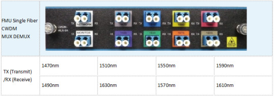
The CWDM technic multiplexes optical signals together on one single fiber. As a universal equipment, it can combine different wavelengths in a CWDM Mux/Demux to achieve this. Coupled with highly reliable passive optics certified for environmentally hardened applications, the CWDM Mux/Demux make operators take full advantage of available fiber bandwidth in local loop and enterprise architectures. CWDM Mux/Demux is a flexible and cost-efficient solution that expand the existing fiber capacity. When there is only one fiber available for network capacity expansion. Then, single fiber CWDM MUX and DEMUX is being used. The single fiber CWDM MUX DEMUX has a simplex line port (shown in the above picture), which is the biggest difference from the bidirectional CWDM MUX DEMUX on the appearance.
Working principle
The single fiber CWDM MUX/DEMUX uses the CWDM wavelengths in a way different from the bidirectional CWDM MUX DEMUX, so it can achieve dual way transmission. Each wavelength in bidirectional CWDM network runs on two opposite directions but just on one direction in single fiber CWDM network. There are two options for you if you want to build a dual way transmission link between two sites. First option is use one wavelength over duplex fiber with dual-fiber CWDM MUX DEMUX, the second option is use two wavelengths (one for TX and the other for RX) over simplex fiber with single fiber CWDM MUX DEMUX.

The picture shown above give us a description of the Use of CWDM Wavelength in Single Fiber CWDM Network. In this network, 16 wavelengths are used to support 8 pairs of dual-way transmission. On site A, there deployed an 8-channel single fiber CWDM MUX DEMUX using 8 wavelengths for transmitting and the other 8 wavelengths for received. On the opposite site B, also a single fiber CWDM MUX and DEMUX is deployed. However, the wavelengths for TX and RX are reversed. For instance, a pair of dual-way signal uses 1270nm for TX and 1290nm for RX on site A, while use 1290nm for TX and 1270nm for RX on site B. This is how the single-fiber CWDM MUX and DEMUX achieving dual-way transmission.
The Ports On CWDM MUX DEMUX
The basic function of the CWDM is to increase the network capacity by combine the data rate of variety wavelengths over the same fiber cable. So the must-have ports for these devices are channel ports supporting different wavelengths or Line port used to connect the WDM MUX/DEMUX.
Channel Port
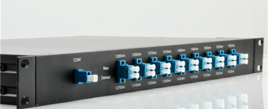
There are 18 type of wavelengths of CWDM in total, from 1270nm to 1610nm with a channel space of 20nm. The following picture shows a CWDM MUX DEMUX with all the 8 CWDM wavelengths: 1470nm, 1490nm, 1510nm, 1530nm, 1550nm, 1570nm, 1590nm, 1610nm.
Line Port
There are two types of line port available for CWDM MUX DEMUX. One is dual fiber line port, and the other is single fiber line port. The selection of the line port depends on applications. If it’s a single-fiber WDM MUX DEMUX, there are only one direction for all the wavelengths to flow in. And the TX port and RX port of every duplex channel port supporting two different wavelengths.
Monitor Port
This port added wto bring more profits to the existing WDM network. A numner of technicians will add a monitor port on CWDM MUX DEMUX for better network monitoring and management. If you choose a single-fiber WDM MUX/DEMUX, the monitor port should be a simplex fiber optic port.

How to Install Your CWDM MUX DEMUX System?
In short, there are four major steps for a CWDM MUX DEMUX system installaltion:
1. Install the Rack-Mount Chassis

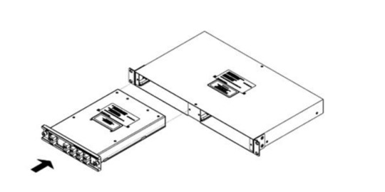
2. Install the CWDM MUX DEMUX Modules
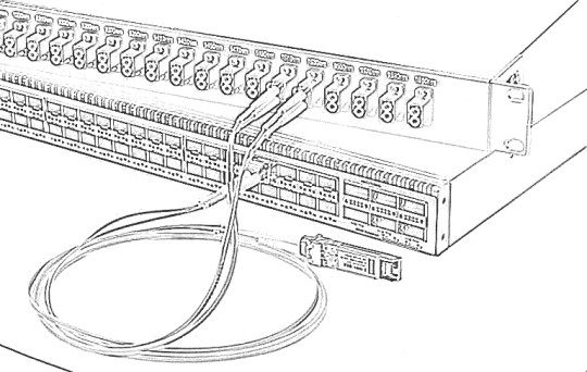
3. Connect the CWDM MUX DEMUX to Switch
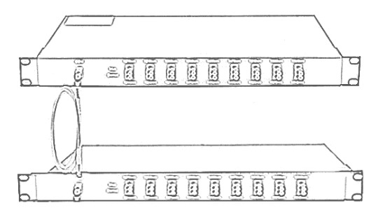
4. Connect the CWDM MUX DEMUX Pairs
How to Select Fiber Optic Transceiver for Single Fiber CWDM MUX and DEMUX
Because of there has two different wavelengths on a duplex channel port, it could be confused when we need to select a CWDM transceivers for the single fiber CWDM network. So how to select it for single fiber CWDM MUX DEMUX? The Key elements is the wavelength for TX. Still take the above example, on site A 1270nm is used for TX, thus, a 1270nm CWDM transceiver should be used. On site B, a 1290nm CWDM transceiver should be used. The fiber optic transceivers used for single fiber CWDM MUX and DEMUX are different on the two sites.
10Gtek Single Fiber CWDM MUX DEMUX Solution
The products for CWDM network mentioned above are available in 10Gtek. 8 Channels Dual LC CWDM MUX/DEMUX are available and the special ports like pass port can be customized. Any interest, please feel free to contact [email protected] for more information.
The following shows 10Gtek Single Fiber 8 Channels Dual LC CWDM MUX/DEMUX channel port details.
0 notes
Text
Can the Hybrid CWDM-DWDM System Work for Higher Capacity?
When facing the capacity-hungry issue, have you ever hesitated over which WDM system should be choose? As the CWDM system is a more economical solution for limited expanding capacity while the expensive DWDM solution enables much higher capacity, which one should be chose is really a tough decision. In order to solve the issue, can we deploy a Hybrid CWDM-DWDM system, for not choosing a wrong solution to increase the network capacity? Thereby, both the bandwidth shortage with CWDM solution or the potential bankruptcy with DWDM solution can be avoided. Let’s seeking the answer.
Can the Hybrid CWDM-DWDM System Work?
Can the Hybrid CWDM-DWDM system work for higher network capacity? The answer is yes. In fact, it is an ideal solution for boosting the network capacity, which is designed with merging DWDM and CWDM traffic seamlessly at the optical layer, taking full use of the WDM technology. In a hybrid CWDM-DWDM system, more channels can be added to deal with the limited capacity and reach in a CWDM system. That’s to say, the hybrid CWDM-DWDM system utilizes the DWDM technology to empower CWDM system, by integrating CWDM and DWDM equipment, which offers true pay-as-you-grow capacity growth and investment protection.
In short, the hybrid CWDM-DWDM system is a simple, plug-and-play option that enables more DWDM channels interleaved with the existing CWDM channels, for transmitting more data signals. It gets the utmost out of CWDM and DWDM technologies in a single system that greatly reduces the cost, simplifies the installation and keeps the system flexibility for bigger network capacity.
How to Build a Hybrid CWDM-DWDM System?
In general, a normal complete optical connection can be simply done by using a length of fiber patch cable to connect two fiber transceivers and then separately inserting the two transceivers into the ports of two switches. While in a hybrid CWDM-DWDM system, both the CWDM Mux Demux and DWDM Mux Demux should be added offering multiple channels to multiplex and demultiplex the signals. Here offers a typical 44 channel hybrid CWDM-DWDM system information for your reference.

From the figure, we can learn that the original CWDM system uses two 8 channel CWDM Mux Demux with wavelengths from 1470 nm to 1610 nm (20nm channel spacing). In order to add more channels for transmitting larger data signals, two pairs of DWDM multi-channel Mux/Demux are deployed separately under the pass band of the existing CWDM filters. In principle, deploying the DWDM multi-channel Mux/Demux in the 1530nm channel can create 25 100 GHz spaced DWDM channels. However, only 19 DWDM channels circled in the following figure are suitable to be added in the hybrid CWDM-DWDM system. It is also the same to the 1550 channel. Hence, this hybrid CWDM-DWDM system totally offers 6 CWDM channels and 38 DWDM channels with less deployment cost but easier installation.

Conclusion
If you come across the capacity-hungry issue and can’t make the decision about which WDM system should be choose for increasing your network capacity, you are highly recommended to deploy a hybrid CWDM-DWDM system. As an economical and future-proofing solution, the hybrid CWDM-DWDM system can completely deal with the issue of bandwidth shortage when building a CWDM system and avoid the potential bankruptcy for a DWDM system. You can just deploy a CWDM system first. Once the capacity the CWDM system offers can’t meet your requirement, you can add DWDM equipment in for more channels to transmit signals. All in all, the hybrid CWDM-DWDM system is an ideal choice that not only costs less for deployment but keeps the flexibility to increase the network capacity.
0 notes
Text
Channel CWDM Mux & DeMux – Features and Applications
Channel CWDM Mux & DeMux – Features and Applications
by http://www.fiber-mart.com
The CWDM are by and large in view of thin coat channel innovation which is the type of item fall under the WDM class. There arrived in a total scope of Class-8 CWDM Mux-Demuxand also OADM that stands for Optical Add Drop Multiplexer units with a specific end goal to meet a wide range of necessities and system arrangements. Likewise, it has across the board…
View On WordPress
0 notes
Text
FS.COM 2017 – A Year Full of Gratitude and Appreciation
2018 is coming. At the end of 2017, Cable Gland with Strain Relief FS.COM has reviewed the whole year and concluded a keyword “innovation and development”. In 2017, we continuously improve product quality and perfect service system to ensure products meet and exceed customer requirements. For instance, FS.COM FMT (multi-service transport) system is engineered to support low-cost 100G DWDM solutions for high-capacity optical links and conducive to save cabinet space. And on the basis of FHD (high-density) cable managing system, we self-developed the FHX system for ultra high-density cabling with easy management of MAC of connections in data centers as simple as plug & play.
In addition, FS.COM has completed the other product system like network switches, 25G transceivers & DAC/AOC, etc. With one year’s hard work, we got many positive comments from industry participants. Here just presents parts of the comments.There is a risk of buying network switches from vendor you haven’t used before or without feedback or recommendations from other people. However, you bought, and FS.COM didn’t let you down. FS.COM offers multiple types of optical transceivers ranging from SFP, SFP+, QSFP+ to 100G QSFP28 optics.
And every transceiver optics is individually tested on corresponding equipment to ensure its full compatibility on your devices. Moreover, we have different types of fiber cables and copper cables to meet various network demands.Last year, we built our USA warehouse to reduce the delivery time and this year, we have built the Germany warehouse and are expanding the European market. The following picture is one of our customers showing the transceiver optics and patch cables on Twitter. CWDM and DWDM Mux/Demux are used to increase the bandwidth of an optical fiber by multiplexing several wavelengths onto it, thus saving valuable optical fibers. We have CWDM Mux/Demux with 4 channels, 8 channels and 18 channels, and DWDM Mux/Demux with 8 channels, 16 channels, 40 channels and 96 channels, which can meet most network demands.
0 notes
Text
CWDM and DWDM Comparison: What’s the Difference?
DWDM (Dense Wavelength Division Multiplexing) is undoubtedly the popular technology in today's optical fiber applications. However, because of its expensive price, many operators without enough money are quite hesitated to use it. Can we use wavelength division multiplexing at a lower cost? Faced with this demand, CWDM (Coarse Wavelength Division Multiplexing) came into being. And in the post, we will take an introduction on the main difference between CWDM and DWDM and which one is your better choice.
CWDM, as the name suggests, is a DWDM close relative. When comparing CWDM vs. DWDM, their differences are mainly two points as follows:
1. CWDM carrier channel spacing is wide, so the same fiber can only reuse 5 to 6 or so wavelength. This is why we call “Dense” and “Coarse”.
2. CWDM modulates laser by using non-cooling laser, but DWDM is used to cooling laser. The cooled laser is thermally tuned and the non-cooled laser is electronically tuned. Since the temperature distribution is very uneven in a wide wavelength range, the temperature tuning is difficult and costly to achieve. CWDM avoids this difficulty, therefore the cost is significantly reduced, the entire cost of CWDM system is only 30% of DWDM.
CWDM provides very high access bandwidth for low cost, and is suitable for popular network structures such as point-to-point, Ethernet, SONET ring, especially for short distance, high bandwidth, and point-intensive communication applications. Building communication between buildings or buildings. In particular, it is worth mentioning that CWDM and PON (passive optical network) with the use. PON is an inexpensive, point-to-multipoint optical fiber communication method. By combining with CWDM, each individual wavelength channel can be used as the virtual optical link of PON to realize the broadband data transmission between the central node and multiple distributed nodes.
At present, several companies are introducing CWDM-related products. Here we mainly introduce CWDM Mux/Demux and DWDM Mux/Demux.
(1). CWDM Mux/Demux Module:
CWDM Mux and CWDM Demux are designed to multiplex multiple CWDM channels into one or two fibers. The core of CWDM Module application is the passive MUX DEMUX unit. The common configuration is 1×4, 1×8, 1×16 channels. Available in 19″ Rack Mount or LGX module package, optional wide band port is available to multiplex with CWDM Channels wavelength.
(2). DWDM Mux/Demux Module:
DWDM Mux and DWDM DeMux are designed to multiplex multiple DWDM channels into one or two fibers. The common configuration is 4, 8, 16 and 40 channels. These modules passively multiplex the optical signal outputs from 4 or more electronic devices, send them over a single optical fiber and then de-multiplex the signals into separate, distinct signals for input into electronic devices at the other end of the fiber optic link.
However, CWDM is the product of cost and performance compromise; inevitably there are some limitations on performance. Industry experts pointed out that CWDM currently exist below the following four points: First, CWDM in a single fiber to support the number of multiplex wavelengths less, resulting in higher cost of expansion in the future; second, multiplexers, multiplexers, etc. The cost of the equipment should be further reduced, these devices can not only DWDM corresponding equipment, a simple modification; Third, CWDM does not apply to metropolitan area networks, metro nodes between the shorter distance, operators in the CWDM equipment expansion on the money can Used to lay more fiber optic cable, get better results; Fourth, CWDM has not yet formed a standard.
From the CWDM and DWDM comparison above, we can know both the benefits and drawbacks of CWDM and DWDM. If the transmission distance is short and cost is low, then CWDM may be your first choice. On the contrary, you can consider DWDM. For more information about CWDM and DWDM, you can visit: Gigalight.
0 notes
Text
CWDM Mux & DeMux - Features and Applications
CWDM Mux & DeMux – Features and Applications
The CWDM are by and large in view of thin coat channel innovation which is the type of item fall under the WDM class. There arrived in a total scope of Class-8 CWDM Mux-Demux and also OADM that stands for Optical Add Drop Multiplexer units with a specific end goal to meet a wide range of necessities and system arrangements.
Likewise, it has across the board applications that require the Channel…
View On WordPress
0 notes
Text
How to Realize 16 Channels Transmission in DWDM Network?
DWDM MUX/DEMUX plays a critical in WDM network building. 16 channels transmission is very common in DWDM networks. How to realize it in a simple way? This article intends to introduce two solutions to achieve 16 channels with different types of components. Which one is more cost-effective and competitive? The comparison between the them also will be explored. Hope it will help you when choosing fiber mux for your DWDM networks.
Solutions to Achieve 16 Channels Transmission in DWDM Network
In order to illustrate the solution more clearly, I take two types of DWDM MUX/DEMUX as an example. One is the traditional 16 channels dual fiber DWDM MUX/DEMUX. Another is two FMU 8 channels dual fiber DWDM MUX/DEMUX. The latter has an expansion port.
Solution One: Using Traditional 16 Channels DWDM MUX/DEMUX
The 16 channel DWDM MUX/DEMUX is a passive optical multiplexer designed for metro access applications. It’s built fiber mux and demux in one unit and can multiplex 16 channels on a fiber pair. In addition, this type of fiber mux also can be added some functional ports like expansion port, monitor port and 1310nm port, which make it possible to increase network capacity easily. The following is a simple graph showing the 16 channels transmission with this traditional DWDM MUX/DEMUX.
Solution Two: Using Two FMU 8 Channels DWDM MUX/DEMUX Modules
The FMU 8 channels DWDM MUX/DEMUX provide 8 bidirectional channels on a dual strand of fiber. Usually they are used together. Unlike the 16 channels DWDM MUX/DEMUX, this FMU 8 channels one has a more compact size, for it only occupies half space in a 1U rack. Put two FMU 8 channels DWDM MUX/DEMUX modules into one 1U two-slot rack mount chassis. two 8 channels DWDM MUX/DEMUX with different wavelengths are connected through the expansion port to realize 16 channels transmission in a DWDM network. Here is a graph showing how to achieve 16 channels DWDM transmission with these two 8m channels fiber muxes. As shown in the figure, two 8 channels DWDM MUX/DEMUX with different wavelengths are connected through the expansion port to realize 16 channels transmission in a DWDM network.
16CH DWDM MUX and Two FMU 8CH DWDM MUX: What’s the Difference When Deployed?
From the content above, we can see both solutions can realize the 16 channels transmission in a DWDM network. Then, are there differences between them? Or which is more competitive? Here is a simple analysis of the two solutions.
Firstly, comparing the two graphs above, the FMU 8 channels DWDM MUX/DEMUX are connected together by an expansion port, that’s why it can deliver 16 channels services like the traditional one. Except for connecting 8 channels DWDM MUX/DEMUX, the FMU fiber mux with expansion port also can be combined with other channels fiber mux like 2 channels, 4 channels or other channels, which offer more flexibility for optical network deployment and upgrade. And you can add DWDM into CWDM networks at some specific wavelengths with FS.COM FMU fiber mux.
Secondly, DWDM MUX/DEMUX price is always an important point that many network operators pay attention to. Therefore, when buying a fiber mux, the cost is a critical point to consider. If you search on Google, you will find the lowest price is $1100 in FS.COM. And the cost of using two 8 channels MUX/DEMUX is the same as the deployment of one 16 channels MUX/DEMUX. However, compared with the 16 channels DWDM MUX/DEMUX, the FMU 8 channels fiber mux provides a competitive solution for small networks which needn’t to buy a full-channel fiber mux that supports all 16 channels or more channels.
Conclusion
From the comparison above, the FMU 8 channels DWDM MUX/DEMUX is more flexible and cost-effective when deployed in WDM networks. How to choose is based on the requirements of your networks. FS.COM supplies two different types of these WDM MUX/DEMUX. Here is a simple datasheet of them. If you have more requirements for additional wavelengths, welcome to visit www.fs.com for more detailed information.
Sources:http://www.fiber-optic-tutorial.com/16-channels-dwdm-mux-demux-in-dwdm-network.html
0 notes
Text
How to Extend 40G Connection up to 80 km?
As 40G connectivity is accelerating, many data centers prepare to migrate from 10G to 40G. But the link distance between 10G and 40G switches is a big challenge. This article can help you extend 40G connection distance.
Current 40G QSFP+ Connection—Max 10 km
As we know, 40GBASE-SR4 QSFP+ is designed for short distance of up to 150m connection. 40GBASE-PLR4 QSFP+ can support long distance link of up to 10 km. Both 40G QSFP+ modules are interfaced with 12-fiber MTP/MPO and can break out into 4x10G connection. To build 10G-40G connection, for instance, using singlemode 8-fiber MTP-LC harness cable to connect 40GBASE-PLR4 QSFP+ and 4x10G SFP+ modules. As the direct connection distance between two 40GBASE-PLR4 QSFP+ optics can reach at most 10km, it’s easy to understand that the connection between 10G and 40G may be shorter. However, we provide a method to extend 40G connection to 80km distance. Continue to read this article and find the answer.

Equipment for Extending 40G QSFP+ Connection
To extend 40G QSFP+ connection distance, we have to use WDM transponder OEO (Optical-Electrical-Optical) repeater. OEO repeater allows connection between fiber to fiber Ethernet equipment, serving as fiber mode converter, or as fiber repeater for long distance transmission. It can also function as CWDM/DWDM optical wavelength conversion. Now we will use a multi-service transport system, including a hot-swappable plug-in OEO card which only occupies 1 slot. The other space can be left for holding more cards such as DCM, EDFA, OLP. On the left side, there is a card for centralized network management.

This is a 4-channel multi-rate WDM transponder with an OEO-10G card containing 8 SFP/SFP+ slots and can support up to 11.3G rate. The OEO card can convert 1G~11.3 Gbps Ethernet signals into a corresponding wavelength in CWDM and DWDM network infrastructures. Transmission distance can reach 80 km.
Except WDM transponder OEO repeater, we still need DWDM Mux/Demux and DWDM SFP+ to extend the distance to 80 km. DWDM Mux/Demux is to combine 4x10G signals of different wavelengths on one single fiber so that it’s the best solution to increase network capacity and save cost. Here we use 40-channel C21-C60 dual fiber DWDM Mux/Demux. So we can choose suitable 10G DWDM SFP+ modules 80km transceiver between the wavelengths of C21 and C60.
For your reference, the equipment for 40G connection extension mentioned above are from FS.COM. You can select those of other specifications according to your own needs.

Extend 40G QSFP+ Connection to 80 km
Install 40GBASE-PLR4 QSFP+ into QSFP+ port of a switch and 4 10GBASE-LR SFP+ into the Ethernet ports of the WDM transponder OEO repeater. Then plug a singlemode 8-fiber MTP-LC harness cable to connect 40GBASE-PLR4 QSFP+ and 4 SFP+ modules. Because of the OEO repeater function, 4x10G Ethernet signals are converted into corresponding wavelengths in DWDM network infrastructure. Then install 4 x 10G DWDM SFP+ transceivers into other four ports of OEO repeater. Next step is to connect DWDM SFP+ modules on the OEO repeater and DWDM Mux/Demux by using LC duplex patch cables. In this way, 40G QSFP+ distance can be extend up to 80 km.

Conclusion
10 km transmission distance is not the limit of 40G connection. From this article, you can extend 40Q QSFP+ to 80 km by mainly applying WDM transponder OEO repeater, DWDM Mux/Demux and 10G DWDM SFP+. If need to break your network distance limit, please visit our site www.fs.com or contact us via [email protected].
Originally published at: http://www.fiber-optic-equipment.com.
0 notes
Text
Hybrid CWDM-DWDM System Boosts Your Network Capacity
Should I choose a medium capacity but more cost-effective CWDM solution, or to adopt the cost-prohibitive DWDM approach with comparably enhanced capacity? This is a problem that consistently faced by WDM technology users. The wrong decision, however, may inevitably lead to bandwidth shortage or even potential bankruptcy derived from unnecessary capacity investment. This article introduces the hybrid CWDM-DWDM solution that combines both CWDM and DWDM technologies within a single system, helping decrease costs and simplify installation while maintain the flexibility to upgrade.
Hybrid CWDM-DWDM System Explanation
Hybrid CWDM-DWDM system utilizes the technology to merge DWDM and CWDM traffic seamlessly at the optical layer. Which allows carriers to add many channels to networks originally designed for the more limited CWDM capacity and reach. In other words, hybrid CWDM-DWDM system is used to empower CWDM system by integrating CWDM and DWDM equipment. Hybrid CWDM-DWDM system deliver true pay-as-you-grow capacity growth and investment protection. It offers a simple, plug-and-play option for creating hybrid system of DWDM channels interleaved with existing CWDM channel plans.
Benefits of Hybrid CWDM-DWDM System
Hybrid CWDM-DWDM system typically provides three benefits for carriers and users:
Reduced Cost: CWDM is more cost-effective than DWDM due to the lower cost of lasers and the filters used in CWDM modules. This cost saving becomes quite significant for large deployments.
Pay-As-You-Grow: Adding one new channels at a time allows for on-demand service introduction with minimal initial investment—a critical feature in terms of reduced OPEX and CAPEX spending.
Investment Protection: Carriers and end-users need always to bear the future growth in mind. With hybrid CWDM-DWDM system, carriers no longer have to choose between CWDM and DWDM—both options can be deployed simultaneously or as part of future growth. This module can be used in either CWDM or DWDM system. Current capital investment can always be used in the upgraded network.
How to Deploy Hybrid CWDM-DWDM System
The CWDM wavelength grid typically has 16 channels spacing at 20 nm intervals, with 8 channels (1470 nm-1610 nm) of them are most commonly used. Within the pass band of these channels, it is capable of adding 25 100 GHz spaced DWDM channels under the 1530nm envelope and 25 more under the 1550nm envelope. However, it is not so practical to add 25 DWDM channels in the pass-band of both the 1530nm and 1550nm CWDM channels. DWDM filter technology does allow 38 additional channels to clear the CWDM archway, which is shown as following.

To add more DWDM channels to the MUX side of the conventional CWDM system, one need to plug in a DWDM MUX with the appropriate channels under the pass band of the existing CWDM filters. The picture below illustrates the configuration of a CWDM system upgraded with 38 additional 100 GHz spaced DWDM channels. This hybrid CWDM-DWDM system consists of 38 DWDM channels and the existing 6 CWDM channels. The equipment required to go from the first architecture to the second are 2 DWDM MUX/DEMUXs, as well as the additional transmitter and receiver pairs. The additional loss incurred by the upgrade is equal to the additional loss of the DWDM elements and the additional connection points.

Flexible Hybrid CWDM-DWDM System Solution by FS.COM
The most vital elements concerning hybrid CWDM-DWDM system are the CWDM MUX/DEMUX and DWDM MUX/DEMUX. FS.COM developed and introduces FMU series products to facilitate installation and operation of WDM MUX/DEMUX. The prominent feature of this series products is that they combine the MUX/DEMUX into half-U plug-in modules, which can be installed in a 1U rack. As for hybrid CWDM-DWDM system, a FMU CWDM MUX/DEMUX and a DWDM half-U plug-in module can be installed together in a FMU 1U rack chassis, facilitating connections of these two modules while allowing for better cable management and network operation in hybrid CWDM-DWDM system.

Conclusion
Hybrid CWDM-DWDM system generally offers a cost-effective and future-proofing approach for service providers and end-users, by overcoming the obstacles faced by users of WDM technology today, providing a starting platform that scales smoothly and protecting the investment. A user can commence with the more cost-effective CWDM technology and then later add DWDM in the when the capacity is required. FS.COM FMU series WDM solution makes the process even easier and more flexible. For more information, please visit www.fs.com or contact [email protected].
Source: http://www.fiber-optic-solutions.com/hybrid-cwdm-dwdm-boost-network-capacity.html
0 notes
Text
Analysis of Power Budget and Link Distance in CWDM System
It can’t be denied that CWDM technology is a cost effective method to increase the capacity in the existing system, which can give different wavelengths to multiple optical signals and multiplex them for transmission through only one single fiber. Different from the DWDM system, the network using CWDM technology are deployed by passive components like passive CWDM Mux Demux, without the need of additional power, which makes CWDM system more commonly used. Do you also plan to build a CWDM system? If yes, you can check the following information for reference, which mainly analyzes the optical power budget in a CWDM system and calculates the CWDM link distance according to the power budget for smoothly deploying a CWDM system.
What’s Optical Power Budget?
Before deploying an optical network, it is very essential to calculate the optical power budget for better deployment. What’s optical power budget? It is just the amount of light available to make a successful fiber connection which can be calculated by analyzing the original output power of the transmitter and the required input power of the receiver. In details, we should firstly learn the optical power that is emitted by the source (also referred to Transmit Power) and the required power of the detector (also called Receiver Sensitivity). Using the first data to subtract the second one, you’ll get the data of the optical power budget which greatly determines the performance of the whole network link.
Here is the equation: Optical Power Budget = Transmit Power - Receiver Sensitivity.
How to Get the Optical Power Budget in a CWDM System?
To estimate the link distance supported by a CWDM system, the optical power budget should be calculated first, which can greatly determine the CWDM link distance. Here will show you a basic CWDM system under an ideal condition to clearly illustrate how to get the optical power budget. In this basic CWDM system, there is a optical transmitter which transmit power is -2 dBm and a optical receiver with -25 dBm receiver sensitivity. Hence, the optical power budget is 23 dB, as shown in the following equation.
Optical Power Budget = Tx Power - Rx Sensitivity = -2 dBm - (-25 dBm) = 23 dB
However, the mentioned CWDM system is just under an ideal condition without loss caused by the signal transmission. In a normal CWDM system, there are many components like passive CWDM Mux Demux, CWDM transceiver inserted. All these components cause insertion loss once they are inserted into the CWDM link. Therefore, when doing the optical power budget, all the loss should be taken into account for calculating the power budget exactly.
Here is more exact equation: Power Budget = Tx Power - Rx Sensitivity - Loss
To get the real power budget of a CWDM system, here offers a simple CWDM link which uses the -2 dBm optical transmitter, -25 dBm optical receiver and four passive CWDM Mux Demux with low insertion loss. Both the stable 4 channel CWDM Mux and stable 4 channel CWDM Demux in the link have 2.0 dB insertion loss, and other two are 8 channel ones feature 2.5dB insertion loss separately, as shown in the figure below. As a result, the total loss caused by the four passive CWDM Mux Demux is 9 dB, resulted from 2.5 dB + 2.0 dB+2.5 dB + 2.0 dB. Then we can get the total power budget, 14 dB. The calculation process is: Power Budget = Tx Power - Rx Sensitivity - Loss = -2 dBm - (-25 dBm) - 9 dB = 14 dB

How to Calculate the Link Distance in the CWDM System?
After knowing the optical power budget, let’s calculate the link distance of the CWDM system according to the following equation: Link Distance = Optical Power Budget/Fiber Attenuation. As there may be some other power loss caused by the factors that we didn’t consider like fiber aging, temperature and poor splice, we often subtract 2 dB buffer from the total optical power budget. Meanwhile, the fiber attenuation is changeable according to the wavelength, usually varying from 0.2 to 0.35 dB/km. In this case, we’ll use 0.35 dB/km as a typical data. Then we can get the link distance is about 34 km. The calculation process is Link Distance = Optical Power Budget/Fiber Attenuation = (14 dB- 2 dB)/0.35 dB/km.
Conclusion
This paper intends to illustrate how to calculate the optical power budget and estimate the link distance of a CWDM system according to the optical power budget, which allows for better budget of deploying the CWDM system and eliminates the unwanted or unnecessary issues which may happen in the system deployment. Besides, if you want to make a cost effective CWDM system, you are suggested to buy CWDM components like cheap passive CWDM Mux Demux, CWDM transceivers from FS.COM, which are of good price and quality.
0 notes
Text
Channel CWDM Mux & DeMux – Features and Applications
Channel CWDM Mux & DeMux – Features and Applications
by http://www.fiber-mart.com
The CWDM are by and large in view of thin coat channel innovation which is the type of item fall under the WDM class. There arrived in a total scope of Class-8 CWDM Mux-Demuxand also OADM that stands for Optical Add Drop Multiplexer units with a specific end goal to meet a wide range of necessities and system arrangements. Likewise, it has across the board…
View On WordPress
0 notes