#CWDM Multiplexer MUX/DEMUX Modules
Explore tagged Tumblr posts
Visit Tumblr Blog
Explore Tumblr blogs with no restrictions, modern design and the best experience.
Last Seen Tumblr Blogs


Fun Fact
The Tumblr office adopted Tommy, an 11-year-old Pomeranian.
Photo

www.10giga.com.cn,45M homes passed with pre-connectorized #FTTHSolution using #Corning #Fiber,But,at #SoarTelecom factory plant,#CWDM,#MPO,#MTP,#DWDM,#PatchCable,#ADSS,#OutdoorCableproduct assembling,You know what, #Corning,Our Core #BareFiber Material supplying ,Stop by asking more about business purposing,contact freely #Cell,(86)13692286535
0 notes
Text
Uses for an optical isolator

Rotators Difference between an Optical Circulator & Isolator & RotatorĪn optical circulator is used to route the incoming light signals from port 1 to port 2 in a way that if some of the emitted light is reflected back to the circulator, it doesn’t exit from port 1 but from port 3. This rotator is used for amplitude modulation of light and is an integral part of optical isolators and optical circulators. What is an optical rotator?Īn optical rotator is typically an in-line Faraday rotator that is designed to rotate the polarization of the input light by 45 degrees. This is what makes it possible to achieve higher isolation. Hence, it adds to the total of 90 degrees when light travels in the forward direction and then the same in the backward direction. It happens because of the change in the relative magnetic field direction, positive one way, and negative the other way. It means that the rotation is positive 45 degrees in the forward direction and negative 45 degrees in the reverse direction. The polarization rotation caused by the Faraday rotator always remains in the same relative direction. Its main component is the Faraday rotator which ensures non-reciprocal rotation while maintaining linear polarization. What is an optical isolator?Īlso known as an optical diode, an optical isolator is an optical passive component that allows the light to travel in only one direction. While some circulators are three-port devices, there are also four-port circulators. In short, it is designed such that the light coming from one port exits from the next port. What is an optical circulator?Īn optical circulator is a high-performance light-wave component that is designed to route the incoming light signals from Port 1 to Port 2 and the incoming light signals from Port 2 to Port 3. Circulator & Isolator & RotatorĪs we are discussing specifically optical passive components, you will learn here about optical circulators, optical isolators, and optical rotators rather than their electronic counterparts. So, if you are curious to know about these little yet important optical passive components, read the blog till the end. We will first talk about what these components exactly are and then share what makes them different from each other. Today, we will discuss three different optical passive components, namely circulator & isolator & rotator. What is a polarization maintaining filter coupler?.A Concise Selection Guide for In-Line Polarizers.What is the importance of 80um PM fiber components?.The Growing Demand for PM Fiber Components in 2023 and Beyond.Why Should Polarization Maintaining Filter Coupler Feature High Extinction Ratio?.Polarizing Beam combiners/splitters (2).High Power Faraday Rotator and Isolator (1).(6+1)X1 Pump and Signal Combiner 2+1X1 Pump Combiner 8CH CWDM Module 16CH CWDM Module 19" rack mount chassis CWDM 1060nm Cladding Power Stripper 1064nm Band-pass Filter 1064nm Components 1064nm Fiber Collimator 1064nm High Power Isolator ABS plastic box Cladding Power Stripper Collimator Compact CWDM Module CWDM CWDM Multiplexer CWDM Mux/Demux CWDM MUX/DEMUX Module DWDM DWDM Multiplexer fiber optica connector fiber optic coupler FTTX Fused Coupler fused wdm FWDM High Power Fused Coupler High power isolator Isolator LGX CWDM Module Mini Size CWDM Mini Size Fused WDM Multimode High Power Isolator OADM optical circulator optical coupler Optical fiber communication optical isolator PLC Splitter pm circulator PM Components pm isolator pump combiner Pump Laser Protector WDM DK Categories
0 notes
Text
arkoptics.com
A passive multiplexer in most networks consists of a mux and demux optical component. The mux combines, or multiplexes, wavelengths onto a fiber. The demux on the other end of the connection splits, or de-multiplexes, the connections.
In DWDM system, DWDM mux demux is two indispensable modules. Mux (Multiplexer) is a module at the transmitter end that brings several data signals together for transporting over a single fiber, while Demux (Demultiplexer) is a module at the receiver end that separates the signals that come together and passes each channel to an optical receiver.
CWDM mux demux (Coarse Wavelength Division Multiplexer/Demultiplexer) is a flexible, low-cost solution that enables the expansion of existing fiber capacity. CWDM multiplexer is for combining signals together, while demultiplexer is for splitting signals apart.
A polarization-maintaining (PM) WDM filter is a small device used to multiplex PM signals while maintaining the output polarization. When you are using highly efficient systems, PM fibers and PM signals play a very critical role in ensuring the desired efficiency.
Fiber Patch Cord & Cable Assembly, often called fiber patch cable, fiber jumper, or fiber patch lead, is a length of fiber cable that terminated with fiber optic connectors (LC, SC, MTRJ, ST and etc.) at each end. The connectors allow fiber optic patch cord to be rapidly connected to an optical switch or other telecommunications/computer device.
Fiber loopback is widely used for various applications. In terms of telecommunication, loopback is a hardware or software method to feed a received signal or data back to the sender. It is very useful for solving physical connection problems.
Fiber terminators(Plug-in type or Build-out type) are used to terminate unused fiber connector ports in fiber optic systems so optical terminators unwanted reflections are not introduced back into the system. It is used in the fiber-optic networks to install on possibly unused ports.
Fiber optic isolator is a passive component used for fiber optic communications. As a magneto-optic device, the purpose of optical isolator is to allow light to be transmitted in only one direction. An optical isolator is a device that is designed to allow the optical signal travel in the forward direction while block reflections that would travel in the backward direction. Optical isolators are critically important in many applications in optical systems.
FBT splitter(fused biconical taper) is the traditional technology in which two fibers are placed closely together, typically twisted around each other and fused together by applying heat while the assembly is being elongated and tapered. A signal source controls the desired coupling ratio. The fused fibers are protected by a glass substrate and then protected by a stainless steel tube, typically 3 mm diameter by 54 mm long. FBT splitters are widely accepted and used in passive optical networks.
The PLC splitters are used to separate or combine optical signals. A PLC (planar lightwave circuit) is a micro-optical component based on planar lightwave circuit technology and provides a low-cost light distribution solution with small form factor and high reliability. PLCs are manufactured using silica glass waveguide circuits that are aligned with a v-groove fiber array chip that uses ribbon fiber. Once everything is aligned and bonded, it is then packaged inside a miniature housing. PLC splitters have high quality performance, such as low insertion loss, low PDL, high return loss, etc.
1 note
·
View note
Text
How to Realize 100KM DWDM Network With FMT 4000E
Nowadays, DWDM technology has been one of the most commonly used technology in optical transport network (OTN) applications due to the increasing bandwidth need of telecommunication providers. Faced with unpredictable traffic requirements and increasing bandwidth demands, FS has developed a new standardized optical transport solution, which called FMT WDM transport platform. And this FMT WDM transport platform is divided into four specific series according to different transmission distance, including CWDM solution FMT 1800, DWDM solution FMT 1600E, 4000E, 9600E. In this post, we will take FMT 4000E optical transport platform as an example to illustrate how does this transport platform realizes 100km network connections and its advantages.
What Is FMT 4000E DWDM Network Transport Platform?
As mentioned above, FMT 4000E DWDM network transport platform is one type of the FMT WDM transport platform series. This optical transport platform is a 4U managed chassis. It is equipped with 16 full-size slots and optical layer modules and a wide range of intelligent services modules can be installed in these slots. Equipped optical devices in FMT 4000E will be illustrated in detail in the following part.


Currently, FS has developed two versions FMT 4000E, but these two versions has different transmission. One version can support 160km transmission, while another can support 100km transmission. And this post will focus on FMT 4000E for 100km. This platform can achieve 100km end-to-end dual fiber bidirectional transport and support up to 40 wavelengths from C21-C60 at 100GHz. In addition, this optical transport platform can be applied in metro/regional networks, such as CATV, FTTH/PON, xDSL triple play services, GSM/3G mobile services, business customers storage services and so on.

How Does the DWDM Network Work By Using FMT 4000E

From the above topology, we can find that the optical signal from the switch will be sent to 40CH DWDM MUX DEMUX at Site A for wavelength division multiplexing. And then the optical power will be lowered by using optical attenuator. And the dispersion will be compensated by DCM. When this process is finished, the booster amplifier (BA) will improve the optical power and extend the transmission distance. After 100km fiber transmission, we need to amplify the signal by using pre-amplifier (PA) and then the optical signal will be compensated by DCM again. At this time, the optical signal will be sent to 40CH DWDM MUX DEMUX at Site B for demultiplexing again. Finally, the optical signal will be sent to the switch.
Why Choose This FMT 4000E DWDM Transport Platform?
This FMT 4000E DWDM transport platform has flexible networking because it is equipped with intelligent DWDM MUX/DEMUX, integrated with DWDM EDFA and DCF-based DCM system management. This platform has high channel density because it has up to 40 DWDM channels. And this platform can achieve 100km end-to-end dual fiber bidirectional transport when the fiber link loss is 0.25dB/km and the fiber type is G.652D. In addition, this platform has monitor online management software, which can allow operators and administrators to monitor the performance of the whole network. When the urgent accident occurs, this network management system can notify the user so as to ensure the safety of the network. This system can also provide real-time management for local and remote network. Besides, it will send email to inform you of the performance of the network.

Conclusion
This FMT 4000E optical transport platform will be a cost-effective option for l00km transmission due to its better network performance and centralized network management. And FS is always striving for meeting your specific needs and this product is customized for each customer. If you are interested in this product, please contact us via [email protected].
0 notes
Text
Single Fiber CWDM MUX and DEMUX Tutorial
Understand Single Fiber CWDM MUX and DEMUX
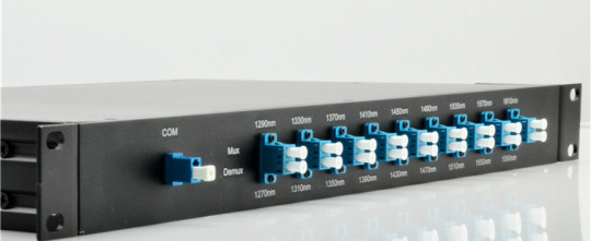
The CWDM technic multiplexes optical signals together on one single fiber. As a universal equipment, it can combine different wavelengths in a CWDM Mux/Demux to achieve this. Coupled with highly reliable passive optics certified for environmentally hardened applications, the CWDM Mux/Demux make operators take full advantage of available fiber bandwidth in local loop and enterprise architectures. CWDM Mux/Demux is a flexible and cost-efficient solution that expand the existing fiber capacity. When there is only one fiber available for network capacity expansion. Then, single fiber CWDM MUX and DEMUX is being used. The single fiber CWDM MUX DEMUX has a simplex line port (shown in the above picture), which is the biggest difference from the bidirectional CWDM MUX DEMUX on the appearance.
Working principle
The single fiber CWDM MUX/DEMUX uses the CWDM wavelengths in a way different from the bidirectional CWDM MUX DEMUX, so it can achieve dual way transmission. Each wavelength in bidirectional CWDM network runs on two opposite directions but just on one direction in single fiber CWDM network. There are two options for you if you want to build a dual way transmission link between two sites. First option is use one wavelength over duplex fiber with dual-fiber CWDM MUX DEMUX, the second option is use two wavelengths (one for TX and the other for RX) over simplex fiber with single fiber CWDM MUX DEMUX.

The picture shown above give us a description of the Use of CWDM Wavelength in Single Fiber CWDM Network. In this network, 16 wavelengths are used to support 8 pairs of dual-way transmission. On site A, there deployed an 8-channel single fiber CWDM MUX DEMUX using 8 wavelengths for transmitting and the other 8 wavelengths for received. On the opposite site B, also a single fiber CWDM MUX and DEMUX is deployed. However, the wavelengths for TX and RX are reversed. For instance, a pair of dual-way signal uses 1270nm for TX and 1290nm for RX on site A, while use 1290nm for TX and 1270nm for RX on site B. This is how the single-fiber CWDM MUX and DEMUX achieving dual-way transmission.
The Ports On CWDM MUX DEMUX
The basic function of the CWDM is to increase the network capacity by combine the data rate of variety wavelengths over the same fiber cable. So the must-have ports for these devices are channel ports supporting different wavelengths or Line port used to connect the WDM MUX/DEMUX.
Channel Port
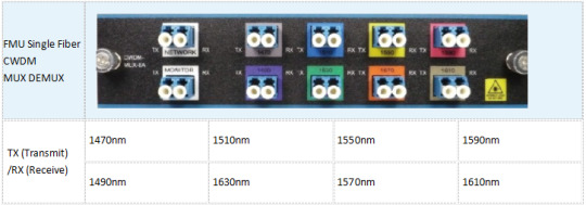
There are 18 type of wavelengths of CWDM in total, from 1270nm to 1610nm with a channel space of 20nm. The following picture shows a CWDM MUX DEMUX with all the 8 CWDM wavelengths: 1470nm, 1490nm, 1510nm, 1530nm, 1550nm, 1570nm, 1590nm, 1610nm.
Line Port
There are two types of line port available for CWDM MUX DEMUX. One is dual fiber line port, and the other is single fiber line port. The selection of the line port depends on applications. If it’s a single-fiber WDM MUX DEMUX, there are only one direction for all the wavelengths to flow in. And the TX port and RX port of every duplex channel port supporting two different wavelengths.
Monitor Port
This port added wto bring more profits to the existing WDM network. A numner of technicians will add a monitor port on CWDM MUX DEMUX for better network monitoring and management. If you choose a single-fiber WDM MUX/DEMUX, the monitor port should be a simplex fiber optic port.

How to Install Your CWDM MUX DEMUX System?
In short, there are four major steps for a CWDM MUX DEMUX system installaltion:
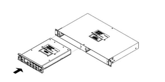
1. Install the Rack-Mount Chassis

2. Install the CWDM MUX DEMUX Modules
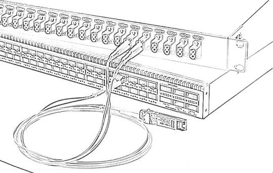
3. Connect the CWDM MUX DEMUX to Switch
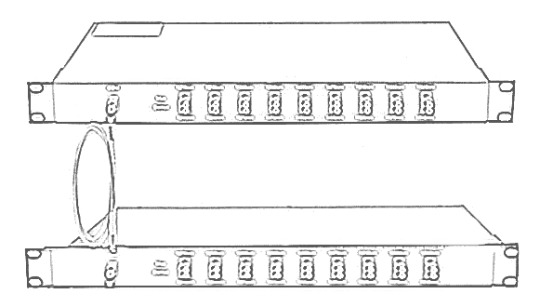
4. Connect the CWDM MUX DEMUX Pairs
How to Select Fiber Optic Transceiver for Single Fiber CWDM MUX and DEMUX
Because of there has two different wavelengths on a duplex channel port, it could be confused when we need to select a CWDM transceivers for the single fiber CWDM network. So how to select it for single fiber CWDM MUX DEMUX? The Key elements is the wavelength for TX. Still take the above example, on site A 1270nm is used for TX, thus, a 1270nm CWDM transceiver should be used. On site B, a 1290nm CWDM transceiver should be used. The fiber optic transceivers used for single fiber CWDM MUX and DEMUX are different on the two sites.
10Gtek Single Fiber CWDM MUX DEMUX Solution
The products for CWDM network mentioned above are available in 10Gtek. 8 Channels Dual LC CWDM MUX/DEMUX are available and the special ports like pass port can be customized. Any interest, please feel free to contact [email protected] for more information.
The following shows 10Gtek Single Fiber 8 Channels Dual LC CWDM MUX/DEMUX channel port details.
0 notes
Text
Different Ports on WDM Mux/Demux
Different Ports on WDM Mux/Demux
In the WDM (wavelength-division multiplexing) system, CWDM (coarse wavelength-division multiplexing) and DWDM (dense wavelength-division multiplexing) Mux/Demux (multiplexer/demultiplexer) modules are often deployed to join multiple wavelengths onto a single fiber. Multiplexer is for combining signals together, while demultiplexer is for splitting signals apart. On a WDM Mux/Demux, there are many…
View On WordPress
0 notes
Photo

www.10giga.com.cn | #CWDM Multiplexer #MUX/#DEMUX #Modules, Why #CWDM,#DWDM,#CWDM,#MPO,#MTP as cost-effective choosing at mulitservice #Fiber Network,? no doublt,Hurry up for RFQ requested to [email protected]
0 notes
Text
The Arrival of 25G CWDM SFP28
With the ever-increasing demands for faster speed and higher density, SFP transceiver modules have undergone several generations of upgrade for signal speed capability and port density updates, from the original SFP to SFP+ and then to the new SFP28 type. 10GbE has encountered bottlenecks due to the surge in demand for high bandwidth. 25G Ethernet becomes the new standard that provides significant density, cost, and power advantages for server switching links. Today we will come to know the CWDM SFP28 with 25G Gigabit Ethernet.
What Is 25G CWDM SFP28?
CWDM SFP28 transceiver operates on four wavelengths (1270, 1290, 1310, and 1330 nm), which combine to be suitable for 100G in data center networks through course wavelength division multiplexing (CWDM). It is an enhanced version of SFP+ designed for 25G signal transmission. The maximum reach is 10 kilometers. The physical structure of the SFP28 is the same as the popular SFP module and SFP+ module, but the electrical interface is upgraded to 25Gbps per channel. The optical connection of CWDM SFP28 is duplex LC fiber patch cables, and the CWDM SFP28 shall be backward compatible with the traditional 10G SFP + pluggable. 25G CWDM SFP28 is a dual directional device with a transmitter, a receiver and a control management interface (2-wire interface) in the same physical package. The 2-wire interface is used for serial ID, digital diagnostics and module control functions. This module provides very high functionality and integration and is accessible via a two-wire serial interface.

What Is the Difference Between CWDM SFP28 and CWDM SFP+?
We know that SFP+ is made to operate at 10Gb/s. SFP28 uses the same common form factor as SFP+, but the electrical interface is upgraded to 25Gbps per channel. CWDM SFP+ transceiver often operates at a nominal wavelength of CWDM wavelength. To be specific, CWDM SFP+ transceiver can support 18 wavelengths from 1270nm to 1610nm, and its transmission distance is from 20km to 80km. While CWDM SFP28 has four main wavelengths of 1270nm, 1290nm, 1310nm, and 1330nm. And its maximum transmission distance is 10km. Compared to SFP+ solutions, SFP28 has higher bandwidth, superior impedance control, and less crosstalk. A report once said the price of per unit of 10G bandwidth for 25G server Ethernet adapters is much lower. 25G SFP28 provides 2.5 times the bandwidth, but the price is not 2.5 times. All in all, the main advantages of SFP28 over SFP+ can be summarized into two points: lower cost and higher bandwidth.
Advantages of Using 25G CWDM SFP28
Compared to 4G, the spectrum bandwidth used by 5G has increased rapidly. 4G uses a maximum spectrum bandwidth of 20MHz, while 5G low-frequency band uses 100MHz bandwidth, and 5G high-frequency band (millimeter wave) uses 800MHz bandwidth with an upper limit of 1GHz. At present, there is still some difficulty in data processing and transmission of 5G high-frequency band (millimeter wave) and large bandwidth. Considering the smooth evolution of 5G equipment and the development of the industry chain, 25G CWDM SFP28 solution can well solve the current 5G millimeter wave pre-transmission problem. In this case, one 100G QSFP28 optical module is used on the antenna side and four 25G CWDM SFP28 optical modules are used on the baseband side. The construction of a 5G millimeter wave pre-transmission bearer network can be completed with only one MUX/DeMUX bridge connection. There is no need for devices to add an additional shunt function to perform rate matching on both ends. In all, 25G CWDM SFP28 can cost-effectively upgrade network bandwidth to support next-generation 50G (2x25G ), 100G (4X25G) and storage solutions for cloud and web-scale data center environments.
Conclusion
SFP28 assembly solution supports a new generation of high-density 25G Ethernet switches that facilitate server connectivity in data centers and provide a cost-effective upgrade path for enterprises deploying 10G Ethernet links in the future. If you are considering to build a 25 Gigabit Ethernet network, you can visit FS.COM, which offers a variety of CWDM SFP28 with famous compatible brands.
Original Source:
http://www.fiber-optical-networking.com/arrival-25g-cwdm-sfp28.html
0 notes
Text
CWDM and DWDM Comparison: What’s the Difference?
DWDM (Dense Wavelength Division Multiplexing) is undoubtedly the popular technology in today's optical fiber applications. However, because of its expensive price, many operators without enough money are quite hesitated to use it. Can we use wavelength division multiplexing at a lower cost? Faced with this demand, CWDM (Coarse Wavelength Division Multiplexing) came into being. And in the post, we will take an introduction on the main difference between CWDM and DWDM and which one is your better choice.
CWDM, as the name suggests, is a DWDM close relative. When comparing CWDM vs. DWDM, their differences are mainly two points as follows:
1. CWDM carrier channel spacing is wide, so the same fiber can only reuse 5 to 6 or so wavelength. This is why we call “Dense” and “Coarse”.
2. CWDM modulates laser by using non-cooling laser, but DWDM is used to cooling laser. The cooled laser is thermally tuned and the non-cooled laser is electronically tuned. Since the temperature distribution is very uneven in a wide wavelength range, the temperature tuning is difficult and costly to achieve. CWDM avoids this difficulty, therefore the cost is significantly reduced, the entire cost of CWDM system is only 30% of DWDM.
CWDM provides very high access bandwidth for low cost, and is suitable for popular network structures such as point-to-point, Ethernet, SONET ring, especially for short distance, high bandwidth, and point-intensive communication applications. Building communication between buildings or buildings. In particular, it is worth mentioning that CWDM and PON (passive optical network) with the use. PON is an inexpensive, point-to-multipoint optical fiber communication method. By combining with CWDM, each individual wavelength channel can be used as the virtual optical link of PON to realize the broadband data transmission between the central node and multiple distributed nodes.
At present, several companies are introducing CWDM-related products. Here we mainly introduce CWDM Mux/Demux and DWDM Mux/Demux.
(1). CWDM Mux/Demux Module:
CWDM Mux and CWDM Demux are designed to multiplex multiple CWDM channels into one or two fibers. The core of CWDM Module application is the passive MUX DEMUX unit. The common configuration is 1×4, 1×8, 1×16 channels. Available in 19″ Rack Mount or LGX module package, optional wide band port is available to multiplex with CWDM Channels wavelength.
(2). DWDM Mux/Demux Module:
DWDM Mux and DWDM DeMux are designed to multiplex multiple DWDM channels into one or two fibers. The common configuration is 4, 8, 16 and 40 channels. These modules passively multiplex the optical signal outputs from 4 or more electronic devices, send them over a single optical fiber and then de-multiplex the signals into separate, distinct signals for input into electronic devices at the other end of the fiber optic link.
However, CWDM is the product of cost and performance compromise; inevitably there are some limitations on performance. Industry experts pointed out that CWDM currently exist below the following four points: First, CWDM in a single fiber to support the number of multiplex wavelengths less, resulting in higher cost of expansion in the future; second, multiplexers, multiplexers, etc. The cost of the equipment should be further reduced, these devices can not only DWDM corresponding equipment, a simple modification; Third, CWDM does not apply to metropolitan area networks, metro nodes between the shorter distance, operators in the CWDM equipment expansion on the money can Used to lay more fiber optic cable, get better results; Fourth, CWDM has not yet formed a standard.
From the CWDM and DWDM comparison above, we can know both the benefits and drawbacks of CWDM and DWDM. If the transmission distance is short and cost is low, then CWDM may be your first choice. On the contrary, you can consider DWDM. For more information about CWDM and DWDM, you can visit: Gigalight.
0 notes
Text
10-Year Forecast – Fiber Optic Sensors
According to ElectroniCast, the combined use of Distributed and Point fiber optics sensors are forecast to reach $5.98 Billion in 2026…
ElectroniCast Consultants, a leading market/technology forecast consultancy, today announced the release of their market forecast and analysis of the global consumption of Fiber Optic Sensors.
According to the study, the combined use of Distributed and Point (local) fiber optics sensors reached $3.38 Billion last year (2016), and the worldwide value is forecast to reach $5.98 Billion in 10-years (2026). Market forecast data in this study report refers to consumption (use) for a particular calendar year; therefore, this data is not cumulative data.
Both the American region and the EMEA region held similar market share in the overall (distributed- and point-types) fiber optic sensor value last year. The Europe, Middle East, Africa region (EMEA) held a very slight lead in relative market (value) share last year; however, the Asia Pacific region (APAC) is projected to take-over the leadership position during the forecast period.
The EMEA region is forecast to have a strong role in the use of distributed fiber optic systems, driven by the region’s use of systems in aviation, as well as in the
Petrochemical, Natural Resources, Energy/Utility application categories.
In terms of fiber optic point sensors, the American region is forecast to maintain the market share lead throughout the 1st-half of the forecast period (2016-2021), mostly led by the use of Fiber Optic Gyros (FOGs) in the Military/Aerospace application category. The consumption values are based on the end-user application and the end-user region.
FOGs held a 65 percent market share of the worldwide Point fiber optic sensor consumption value in 2016. “All regions, thanks mainly to increases in the use in aviation and military critical mission applications (Unmanned Aerial Vehicle/UAV and missile guidance, navigation, north finding/tracking, robotics, aviation and aeronautics and other) are forecast to show impressive increase consumption quantity (volumes) and values for the FOG systems,” said Stephen Montgomery, Director of the Fiber Optics Components group at ElectroniCast Consultants.
The market forecast of the Distributed Sensors is segmented by the following applications:
Manufacturing Process/Factory
Civil Engineering/Construction (buildings, bridges, tunnels, etc)
Military/Aerospace/Security
Petrochemical/Energy/Utilities/Natural Resources
Biomedical/Science
The Fiber Optic Point Sensor Forecast further segmented by the following sensing/measuring quantity (measurand) types:
Mechanical Strain
Temperature
Pressure
Chemical, Gas, Liquid
Vibration, Acoustic, Seismic
Displacement, Acceleration, Proximity
Electric, Current and Magnetic Field - Fiber Optic Sensors
Rotation (such as Fiber Optic Gyroscopes: FOGs)
“ElectroniCast counts each Point fiber optic sensor as one unit; however, the volume/quantity (number of units) of Distributed fiber optic sensors is based on a complete optical fiber line/link, which we classify as a system. Since a distributed optical fiber line (system) may have 100s of sensing elements in a continuous-line, it is important to note that we count all of those sensing elements in a distributed system as one (system) unit – only. Distributed fiber optic sensor systems involve the optic fiber with the sensors embedded with the fiber; also included is the optoelectronic transmitter/receiver, connectors, optical fiber, cable (fiber jacket) the sensor elements, and other related components,” Montgomery added.
According to ElectroniCast, the combined use of Distributed and Point fiber optics sensors reached $3.38 Billion in 2016…
Continuous Distributed and Point Fiber Optic Sensor
Global Consumption ($3.38 Billion in 2016)
Source: ElectroniCast Consultants
Tags: CWDM Multiplexer, DWDM Multiplexer,19" rack mount chassis CWDM, CWDM MUX/DEMUX Module, LGX CWDM Module,8CH CWDM Module, 16CH CWDM Module, 100GHz DWDM Mux/Demux, 200GHz DWDM Mux/Demux
DK Photonics – www.dkphotonics.com specializes in designing and manufacturing of high quality optical passive components mainly for telecommunication, fiber sensor and fiber laser applications,such as 1064nm High Power Isolator,1064nm Components, PM Components, (2+1)x1 Pump Combiner,Pump Laser Protector,Mini-size CWDM,100GHz DWDM,Optical Circulator,PM Circulator,PM Isolator,Fused Coupler,Mini Size Fused WDM.
0 notes
Link
: CWDM Mux and Demux Modules are available in 4, 8 and 16 channel configurations. These modules passively multiplex the optical signal outputs from 4 or more electronic devices, send them over a single optical fiber and then de-multiplex the signals into separate, distinct signals for input into electronic devices at the other end of the fiber optic link.
0 notes
Text
How to Realize 16 Channels Transmission in DWDM Network?
DWDM MUX/DEMUX plays a critical in WDM network building. 16 channels transmission is very common in DWDM networks. How to realize it in a simple way? This article intends to introduce two solutions to achieve 16 channels with different types of components. Which one is more cost-effective and competitive? The comparison between the them also will be explored. Hope it will help you when choosing fiber mux for your DWDM networks.
Solutions to Achieve 16 Channels Transmission in DWDM Network
In order to illustrate the solution more clearly, I take two types of DWDM MUX/DEMUX as an example. One is the traditional 16 channels dual fiber DWDM MUX/DEMUX. Another is two FMU 8 channels dual fiber DWDM MUX/DEMUX. The latter has an expansion port.
Solution One: Using Traditional 16 Channels DWDM MUX/DEMUX
The 16 channel DWDM MUX/DEMUX is a passive optical multiplexer designed for metro access applications. It’s built fiber mux and demux in one unit and can multiplex 16 channels on a fiber pair. In addition, this type of fiber mux also can be added some functional ports like expansion port, monitor port and 1310nm port, which make it possible to increase network capacity easily. The following is a simple graph showing the 16 channels transmission with this traditional DWDM MUX/DEMUX.
Solution Two: Using Two FMU 8 Channels DWDM MUX/DEMUX Modules
The FMU 8 channels DWDM MUX/DEMUX provide 8 bidirectional channels on a dual strand of fiber. Usually they are used together. Unlike the 16 channels DWDM MUX/DEMUX, this FMU 8 channels one has a more compact size, for it only occupies half space in a 1U rack. Put two FMU 8 channels DWDM MUX/DEMUX modules into one 1U two-slot rack mount chassis. two 8 channels DWDM MUX/DEMUX with different wavelengths are connected through the expansion port to realize 16 channels transmission in a DWDM network. Here is a graph showing how to achieve 16 channels DWDM transmission with these two 8m channels fiber muxes. As shown in the figure, two 8 channels DWDM MUX/DEMUX with different wavelengths are connected through the expansion port to realize 16 channels transmission in a DWDM network.
16CH DWDM MUX and Two FMU 8CH DWDM MUX: What’s the Difference When Deployed?
From the content above, we can see both solutions can realize the 16 channels transmission in a DWDM network. Then, are there differences between them? Or which is more competitive? Here is a simple analysis of the two solutions.
Firstly, comparing the two graphs above, the FMU 8 channels DWDM MUX/DEMUX are connected together by an expansion port, that’s why it can deliver 16 channels services like the traditional one. Except for connecting 8 channels DWDM MUX/DEMUX, the FMU fiber mux with expansion port also can be combined with other channels fiber mux like 2 channels, 4 channels or other channels, which offer more flexibility for optical network deployment and upgrade. And you can add DWDM into CWDM networks at some specific wavelengths with FS.COM FMU fiber mux.
Secondly, DWDM MUX/DEMUX price is always an important point that many network operators pay attention to. Therefore, when buying a fiber mux, the cost is a critical point to consider. If you search on Google, you will find the lowest price is $1100 in FS.COM. And the cost of using two 8 channels MUX/DEMUX is the same as the deployment of one 16 channels MUX/DEMUX. However, compared with the 16 channels DWDM MUX/DEMUX, the FMU 8 channels fiber mux provides a competitive solution for small networks which needn’t to buy a full-channel fiber mux that supports all 16 channels or more channels.
Conclusion
From the comparison above, the FMU 8 channels DWDM MUX/DEMUX is more flexible and cost-effective when deployed in WDM networks. How to choose is based on the requirements of your networks. FS.COM supplies two different types of these WDM MUX/DEMUX. Here is a simple datasheet of them. If you have more requirements for additional wavelengths, welcome to visit www.fs.com for more detailed information.
Sources:http://www.fiber-optic-tutorial.com/16-channels-dwdm-mux-demux-in-dwdm-network.html
0 notes
Text
Comparison Between CWDM & DWDM Technology
by Fiber-MART.COM
For a better signal transmission in fiber-optic communication, different kinds of technologies are applied to the industry. Wavelength-division multiplexing (WDM) is one of the commonly used technologies which multiplexes a number of optical carrier signals onto a single optic fiber by using different wavelengths of laser light. That is to say, WDM enables two or more than two wavelength signals to transmit through different optical channels in the same optical fiber at the same time.
In the WDM system, there are two types of divisions –
CWDM
(coarse wavelength division multiplexing) and DWDM (dense wavelength division multiplexing). They are both using multiple wavelengths of laser light for signal transmission on a single fiber. However, from the aspects of channel spacing, transmission reach, modulation laser and cost, CWDM and DWDM still have a lot of differences. This article will focus on these distinctions and hope you can have a general understanding about CWDM and
DWDM
technology. Channel SpacingAs their names suggest, the words “coarse” and “dense” reveal the difference in channel spacing. CWDM has a wider spacing than DWDM. It is able to transport up to 16 wavelengths with a channel spacing of 20 nm in the spectrum grid from 1270 nm to 1610 nm. But DWDM can carry 40, 80 or up to 160 wavelengths with a narrower spacing of 0.8 nm, 0.4 nm or 0.2 nm from the wavelengths of 1525 nm to 1565 nm (C band) or 1570 nm to 1610 nm (L band). It is no doubt that DWDM has a higher performance for transmitting a greater number of multiple wavelengths on a single fiber. Transmission ReachSince the wavelengths are highly integrated in the fiber during light transmission, DWDM is able to reach a longer distance than CWDM. The amplified wavelengths provide DWDM with the ability of suffering less interference over long-haul cables. Unlike DWDM system, CWDM is unable to travel unlimited distance. The maximum reach of CWDM is about 160 kilometers but an amplified DWDM system can go much further as the signal strength is boosted periodically throughout the run. Modulation LaserCWDM system uses the uncooled laser while DWDM system uses the cooling laser. Laser cooling refers to a number of techniques in which atomic and molecular samples are cooled down to near absolute zero through the interaction with one or more laser fields. Cooling laser adopts temperature tuning which ensures better performance, higher safety and longer life span of DWDM system. But it also consumes more power than the electronic tuning uncooled laser used by CWDM system. CostBecause the range of temperature distribution is nonuniform in a very wide wavelength, so the temperature tuning is very difficult to realize, thus using the cooling laser technique increases the cost of DWDM system. Typically, DWDM equipment is four or five times more expensive than CWDM equipment. ConclusionCWDM and DWDM are both coming from the WDM technology that is capable of conveying multiple wavelengths in a single fiber. But with different characteristics, people should think twice before choosing the CWDM or DWDM system. CWDM usually costs less but its performance is far behind DWDM. Both your requirements and budget need to be taken into consideration. Moreover, the WDM products including CWDM mux/demux module, DWDM mux/demux module and
optical splitter
are highly welcome in the market.
0 notes
Text
Economical Solutions for 10G to 40G Connection
With the accelerated development of optical network, there exist more and more capacity-hungry applications in 10G networks today. To solve this problem, experts put forward the 10G to 40G connection as an ideal solution. However, due to the high migration cost, we are prevented from making the migration. Do you also meet this issue? In this paper, it will offer several solutions for making 10G to 40G connections with less cost. Hope you can find one that suits your network.

Economical Solutions for 10G to 40G Short Connection
How to make a short link between 10G and 40G switches? You can choose the 40GBASE-SR4 QSFP+ module that supports the 40G network at length up to 150 m. Meanwhile, four 10GBASE-SR SFP+ modules are required. So is the MTP-LC harness cable for connecting QSFP+ and four SFP+ modules. In details, FS.COM offers OM3 MTP-LC harness cable supporting 40G connection up to 100 m and OM4 up to150 m. All these equipment mentioned above are available at FS.COM with good prices. For the details, you can learn from the following table.

If the link distance is longer than 150 m in your network, 40GBASE-CSR4 QSFP+ module may be a better choice. It can transmit the 40G signals longer, up to 400 m. As for the fiber patch cable, you can still chosse OM3 or OM4 MTP-LC harness cable. In general, the OM3 provided by FS.COM enables the connection up to 300 m, while OM4 up to 400 m. When making a short 10G to 40G migration, you can just choose FS.COM as an ideal fiber optical manufacturer. It offers all the equipment your network needs, including 10G and 40G switches, SFP+ and QSFP+ module and MTP-LC patch cable.
Economical Solutions for 10G to 40G Long Connection
Do you need to make a long 10G to 40G migration? FS.COM also offers several cost effective solutions. For example, up to 1km, 10km, 40km or even 80km 10G to 40G connection solutions. Let’s talk about the detail information of these solutions.
Spending Less for up to 40km 10G to 40G Connection
You can use the 40GBASE-PLRL4 QSFP+ and 10GBASE-LR SFP+ modules to support the 10G to 40G migration up to 1 km. The 40GBASE-LRL4 QSFP+ is also a good choice. As for the fiber patch cable, you can choose the 8 fibers single mode MTP-LC harness cable. Once the distance is longer than 1 km, your are suggested to use the 40GBASE-LR4 QSFP+ and 40GBASE-PLR4 QSFP+ modules. These two kinds of fiber transceiver modules enable the connection at lengths up to 10 km. It the link distance is up to 40 km, then you can use the 40GBASE-ER4 QSFP+ module. Here are the related equipment offered by FS.COM.

Spending Less for up to 80km 10G to 40G Connection
Have you ever felt puzzled about whether the 10G to 40G connection can be extended to 80 km? Here you’ll find the answer is yes. How to deploy 80km 10G to 40G connection? You should add the extra equipment, including two DWDM Mux Demux, two WDM transponder OEO (Optical-Electrical-Optical) repeaters and several DWDM SFP+ modules, to your network.
In order to make a smooth 80km 10G to 40G migration, we should add the WDM transponder OEO repeater into the 10G to 40G link. It can not only act as fiber repeater for long distance transmission, but also CWDM/DWDM optical wavelength converter. When the 10G signals pass through the WDM transponder OEO repeater, it will be converted into several DWDM singals. Then you should use the DWDM Mux Demux to multiplex, transmit and demultiplex them. And finally another WDM transponder OEO repeater is required to convert the DWDM singals into 10G signals again. Hence, you can finally achieve the up to 80km 10G to 40G connection. As for the equipment the network requires, you can also order them from FS.COM with good prices.

Conclusion
FS.COM is an ideal fiber optical manufacturer that offers very cost effective solutions for 10G to 40G connection. These solution can support not only the short 10G to 40G migration at lengths up to 400 m, but also the long migration with reach 1km, 10km or even up to 40km. Moreover, if you want to extend the 10G to 40G connection up to 80 km, you can order the extra equipment like DWDM Mux Demux, WDM transponder OEO repeaters and DWDM SFP+ modules from FS.COM with good price. All the equipment mentioned above have been tested to assure 100% compatibility.
Original source: http://www.chinacablesbuy.com/economical-solutions-for-10g-to-40g-connection.html
0 notes
Text
Optical Transponder (O-E-O) Used in WDM Network
WDM technology is commonly used in today’s optical network. It basically assigns each service (10G LAN, SONET/SDH, Fiber Channel, etc) an independent dedicated wavelength—which then is multiplexed into one single fiber. Eliminating the use of multiple fibers while increasing fiber capacity, WDM system is beneficial to both service providers and end users. Optical transponder, also referred to as O-E-O (optical-electrical-optical), serves as an integrated part of WDM system and it is critical for signal transmission in the whole system. This article will guide you through how optical transponder operates in a WDM network.
Basics of Optical Transponder (O-E-O)
The optical transponder (O-E-O) works as a re-generator which converts an optical input signal into electrical form, then generates a logical copy of an input signal and uses this signal to drive a transmitter to generate an optical signal at the new wavelength (optical-electrical-optical). Its most prominent feature is that it automatically receives, amplifies, and then re-transmits a signal on a different wavelength without altering the data/signal content. Clients can be electrical or optical (1310 or 1550 nm), co-located or some distance away. Line side interfaces can be fiber, CWDM or DWDM with a variety of reaches supported.

Common Applications of Optical Transponder (O-E-O)
Optical transponder is widely accepted in WDM networking and many other applications. let’s go through some commonly used ones.
1. Multimode to single-mode conversion
Some optical transponders can convert from multimode to single-mode fiber, short reach to long reach lasers, and/or 850/1310 nm to 1550 nm wavelengths. Each optical transponder module is protocol transparent and operates fully independent of the adjacent channels.

2. Redundant fiber path
Each optical transponder module can also include a redundant fiber path option for extra protection. The redundant fiber option transmits the source signal over two different optical paths to two redundant receivers at the other end. If the primary path is lost, the backup receiver is switched on. Since this is done electronically, it is much faster and more reliable.

3. Repeater
As an optical repeater, some optical transponders effectively extend an optical signal to cover the desired distance. With the clock recovery option, a degraded signal can be dejittered and retransmitted to optimize signal quality.

4. Mode Conversion
Mode conversion is one of the quickest and simplest ways of extending multimode optical signals over greater distances on signal-mode fiber optics. And most receivers are capable of receiving both multimode and single-mode optical signals.

5. Wavelength Conversion
Wavelength conversion in commercial networks today is only carried out by optical transponder. We know that optical network equipment with conventional fiber interfaces like LC, SC, ST, etc operates over legacy wavelength of 850 nm, 1310 nm, and 1550 nm. Which means they must be converted to CWDM or DWDM wavelength to fit in the system, and this is what WDM transponders used for—converse wavelength by automatically receiving, amplifying, and re-transmitting a signal on a different wavelength without altering the data/signal content. The following picture depicts the conversion process: a 10G switch (with signal output of 1310 nm) is to be linked to a CWDM Mux/Demux channel port (1610 nm). An optical transponder with a standard SMF SFP+ and a 1610nm CWDM SFP+ is adopted between the switch and CWDM Mux/Demux, thus the wavelength conversion is realized by the optical transponder.

Network Structure with Optical Transponder
Then how exactly optical transponder benefits your network system? Here we provide two possible configurations of network over WDM ring which deploys optical transponder.
For line network over a WDM ring
The line network consists basically of two point-to-point links between A-B and B-C, each requiring transponders at the endpoints. If node B fails, communication between A and C should still be possible, because B can be bypassed by the two adjacent optical transponders. For this the protection in/outputs of the transponders are connected by a bypass link. If node B fails, S1 in both transponders switch to the protection connection.

For star network over a WDM ring
As for a star network over a WDM ring, where the nodes A, C and D are connected to the star node B. Node B has a backup node B’ for redundancy. Here the protection in/outputs of the transponders are used to connect the nodes A, C and D to node B’ if node B failed.

Conclusion
Optical transponder holds a critical position in WDM networking system and cannot simply be underestimate. We have illustrated the functionality and applications of optical transponder, as well as presenting possible configurations of network over WDM rings. Hope that may help you to have a better understanding of the optical transponder.
Source: http://www.fiber-optic-solutions.com/optical-transponder-o-e-o-wdm-network.html
0 notes