#Cabletesting
Explore tagged Tumblr posts
Visit Tumblr Blog
Explore Tumblr blogs with no restrictions, modern design and the best experience.
Last Seen Tumblr Blogs


Fun Fact
Tumblr.com is the 103rd most visited website in the world.
Text
USB C + HDMI combo panel-mount cable sample 🔌🖥️
We got this nifty panel-mount cable with a combo action: both USB C and DVI/HDMI connectors on both ends. This could be handy for single-board computers like Raspberry Pi's or our RP2040/RP2350 boards with DVI outputs
Since we're testing our Metro RP2350 with HSTX/DVI output anyway, this is a good time to test the cable out - some things we test with USB C cables: verify it enumerates in all 4 orientations (ya never know) and check it with a USB PD sink that requests various voltages. So far, so good; we'll get some of these into the shop in the next few weeks.
#usb#usbc#hdmi#dviconnectors#panelmount#raspberrypi#rp2040#rp2350#singleboardcomputer#dvicables#usbcables#techinnovation#cabletesting#electronics#makerspace#hardwaredesign#techgear#embeddedengineering#techtesting#cableaccessories#productdesign#diyelectronics#techdevelopment#embeddedprojects#techgadgets#cablemanagement#futuretech#hardwarehacks#electronicsdesign#techupgrades
8 notes
·
View notes
Text

Dive into the next era of electrical inspections with SMART Infrared Windows!
Wondering how to combine cutting-edge technology with proven safety measures?
Our IR window boast a resilient design, 1/4 turn locking system, and an embedded RFID chip, ensuring a smarter and safer inspection experience.
Ready to elevate your maintenance game?
#Relaytesting#Relayrepairing#Breakerservicing#Circuitbreaker#Breakerrepairing#Breakeroverhauling#ACB#VCB#SF6breaker#Cabletesting#Siemensrelay#Kyoritsu#ABBrelay#ABBbreaker#Schneiderrelay#Schneiderbreaker#Arevabreaker#Switchyardtesting
0 notes
Text
Reflectometers for metal cables: noise filtering, propagation coefficient, and its determination methods
Let's see how the cables measure influence the range of the reflectometer. How do the noise filtering mode and methods for determining the unknown propagation coefficient affect the measurement accuracy?
KEY FACTORS FOR CABLES
The reflectometer's detection range depends on the cross-section of the cable cores, the overall quality of the cable, as well as on the way the reflectometer is connected to the cable being tested. The larger the cross-section of the cable cores, the less attenuation the electrical pulse supplied by the reflectometer to this cable undergoes and the longer the distance it covers. Old or defective cables may have reduced insulation resistance or increased attenuation. This significantly reduces the ability of the cable cores to conduct electrical signals and, as a result, reduces the maximum distance. The connection of the reflectometer to the cable must be done so that a pulse with the maximum possible amount of energy is emitted from the reflectometer to the cable.
NOISE FILTERING
I want to eliminate the noise in more detail, as it is on any cable. Many reflectometers have a digital noise filtering mode that obliterates the noise from 50 Hz to 1 GHz. This mode is designed primarily for lineworkers dealing with cables near sources of strong electromagnetic interference (for example, railway contact networks, power lines, or antenna poles). The operator can select a filter type with the required characteristics for each test to ensure the acceptable quality of the resulting reflectogram. Suppose an unexpected random voltage value appears in the line during the measurement. In that case, the noise-filtering mode gets turned on automatically. A multi-level and multifunctional filtering system allows one to check antennas and cellular nodes with some received signal interference.

In some cases, the noise-filtering subsystem may slow down the OTDR operation to such an extent that the display becomes unusable. A good example is filtering the noise the power supply induces (60 Hz). One period of alternating current with a frequency of 60 Hz is 16.7 ms. Therefore, it also takes 16.7 ms to generate one point on the reflectometer display. It will take no less than 5.12 seconds to refresh all the 256 image pixels on the display. One way to compensate for this delay is to store the denoised reflectogram. Writing data to the device memory will take some time, but subsequent operations will be as fast as if the filter were turned off. The "averaging" mode, often provided by the manufacturer to eliminate interference at maximum gain, is no exception. This mode also decreases the refresh rate of the display. Four times less noise means the screen is refreshed sixteen times slower. When the image refresh speed is reduced significantly, it becomes difficult to work with the display, so this mode should be used only when necessary. One more thing to mention: cables for digital data transmission should be tested using short pulses with a duration of 2, 10, or, in extreme cases, 100 ns. They do not affect nearby pairs under load, so the data transmission devices' error detection system will not flag them as such.
PROPAGATION COEFFICIENT AND METHODS FOR ITS DETERMINATION
As already mentioned, the reflectometer determines the distance to the abnormal spot based on the signal propagation speed in the cable and the time it takes to reach the point in question and return. In most cases, speed is expressed as a unitless coefficient, the ratio of the signal propagation speed in a given cable to the speed of light. It is an empirically determined value. Reflectometers from different manufacturers require one to set the wave propagation speed, called the Velocity of Propagation (VOP) or Velocity Factor (VF). Typically, this parameter is expressed as a fraction of the speed of light and can have a value from 0.3 to 1. A cable with a VOP value of 0.66 allows an electrical signal to be transmitted at 66% of the speed of light. Some manufacturers express this parameter in terms of actual speed, and then it can range from 45 to 150 m/ms. The choice of the VOP (VF) parameter significantly impacts the accuracy of any measurement made. Therefore, to obtain the most correct results possible, it is necessary to learn the methods for determining the propagation factor for each specific cable.
VOP DETERMINATION METHODS UNDER DIFFERENT CONDITIONS
Suppose the pulse propagation coefficient for the cable is unknown. In that case, an experiment can either calculate or determine it.
1. The insulating material's dielectric constant (ε) is a known value.
VOP=1/√(ε),
where ε is the relative dielectric constant for a given cable. For example, for polyethylene, ε = 2.25. Therefore, VOP = 1/√2.25 = 0.667.
2. For the first experiment, one needs a short cable of the same type as the tested cable. Connect the reflectometer to the cable section and adjust it so that the pulse reflected from the end of the section is clearly visible on the display. Move the cursor to the beginning of the pulse and start changing the VOP coefficient until the measured distance to the end of the cable is equal to its actual length (mind the length of the leads). The longer the cable, the more accurate the obtained VOP value will be.
3. A similar experiment occurs when the cable length is known, and it has a non-defective pair. Connect the reflectometer to the pair and adjust VOP until you get the cable length you already know on the screen. Again, account for the probing leads. Suppose this technique is applied to thick multi-pair cables. In that case, ensuring that the reference and tested pairs belong to the same cable layer is necessary. The length of a pair of outer layers significantly exceeds the length of a pair of inner ones.
4. If the cable length is known, but there is no suitable pair for comparison, then it is necessary to have access to the cable from both sides.
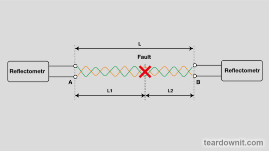
Roughly pick a VOP value and determine the approximate distance (L1) to the fault on side A. Using the same VOP value, determine the approximate distance (L2) to the fault on side B. The exact distance to the damage can be calculated with L1 and L2.
From side A, according to the formula: (L1/(L1 + L2)) x L, where L is the known cable length. From side B, according to the formula: (L2/(L1 + L2)) x L, where L is the known cable length.
0 notes
Text
#cabletester#cable#cableassembly#cableinstallation#cablemanagement#cableindustry#cabletestermarketreport#cabletestermarketresearch#cabletestermarketsize#cabletestermarketshare#cabletestermarketgrowth#grandresearchstore
0 notes
Text
Network Cable Tester Market 🔌📈 – Doubling from $1.2B to $2.4B by 2034! 7.2% CAGR ahead!
Network Cable Tester Market is projected to grow from $1.2 billion in 2024 to $2.4 billion by 2034, at a CAGR of 7.2%. As the demand for efficient network infrastructure and seamless connectivity rises, cable testers are becoming indispensable in IT, telecommunications, and industrial automation.
To Request Sample Report : https://www.globalinsightservices.com/request-sample/?id=GIS23007 &utm_source=SnehaPatil&utm_medium=Article
Market Insights & Growth Trends
Top Segments:
Copper cable testers lead the market (45% share), valued for their cost-effectiveness in traditional network setups.
Fiber optic testers follow (35% share), driven by increasing fiber optic deployments for high-speed internet and data centers.
Coaxial testers account for 20% of the market, supporting broadcast and surveillance networks.
Regional Overview:
North America dominates with strong technological infrastructure and heavy investments in network expansion.
Europe follows, with stringent regulations and rising fiber optic adoption fueling growth.
Asia-Pacific is an emerging hotspot, led by rapid industrialization, urbanization, and smart city initiatives in countries like China and India.
Key Players: Fluke Networks, Ideal Industries, and Klein Tools are at the forefront, focusing on advanced testing technologies, automation, and connectivity solutions.
Future Market Outlook
By 2028, market volume is expected to grow from 12 million to 20 million units, propelled by IoT, smart technologies, and increasing data consumption. Advanced digital, wireless, and automated testers are set to transform network infrastructure testing.
#networkcabletester #telecomindustry #fiberoptictesting #itnetworking #connectivitysolutions #cabletesting #datacenters #networkexpansion #highspeedinternet #coppercable #fiberoptic #wirelessnetworking #networktools #itprofessionals #telecomsolutions #smartcities #industrialautomation #networkanalyzer #digitaltesting #telecomtech #broadband #wirelesstechnology #techinnovation #networkinstallation #iot #cybersecurity #datacenterinfrastructure #cabletester #businessconnectivity #enterpriseit #testingtools #futureofconnectivity #networkreliability #cloudcomputing #internetinfrastructure #networktroubleshooting #fiberdeployment #networksolutions #digitaltransformation #broadbandexpansion #connectivitysolutions #advancedtechnology #itmanagement #networkengineer #signaltesting
0 notes
Video
tumblr
everything you need to know about 10kw/h battery comprehensive test everything you need to know about 10kw/h battery comprehensive test In this video, I’ll show you everything you need to know about 10kw/h battery comprehensive test. Enjoy and subscribe this video! BE MY FRIEND: Add me on Facebook: https://www.facebook.com/113939161676454 Add me on Youtube: https://www.youtube.com/channel/UCE7Oz5AMt8SZdLEFvicR36Q Add me on Blogger: http://ajpower2022.blogspot.com/ Add me on Tiktokapp: https://www.tiktok.com/@ajpowerleesa Add me on Twitterapp: https://twitter.com/@AjpowerLee80204 everything you need to know about 10kw/h battery comprehensive test please contact us immediately if you are interested in. #everything #need #know #10kw/h #battery #comprehensive #test #Ajpower #Leesa #AjpowerLeesa #2017jeepcherokeebatteryreplacement #ACwithoutBatteryWapda #12vsolarpanelbatterycharger #amazingideafor18650battery #12vbatteryprice #ampedoutdoorsbattery #agmbattery #BeautifulAndFastestStoneStaircase- #18650batterydiedfix #cabletester
0 notes
Text
#etekcables#ethernetcables#usa#cat5ecables#cat5eplenum#installation#voip phone#voipservices#structuredcabling
0 notes
Photo

Tan delta/ partial discharge cable testing on a 28kv feeder #substation #cabletesting #highvoltage #PD #electricity @highvoltage_industries Posted by @substation_electrical4 https://www.instagram.com/p/CeSPRCBrt-9/?igshid=NGJjMDIxMWI=
0 notes
Video
instagram
Happy Thursday. Found cables in a box. So continuity testing before putting them in another box! 😉 Video links in the Bio 😉 #tmtgcommunity #themusictechguyuk #musictechguyuk #musician #vintagekeyboard #vintagesynthesiser #studiotester #cabletesting https://www.instagram.com/p/CRWdXZlqRbA/?utm_medium=tumblr
#tmtgcommunity#themusictechguyuk#musictechguyuk#musician#vintagekeyboard#vintagesynthesiser#studiotester#cabletesting
0 notes
Text

Question of the day
#Relaytesting#Relayrepairing#Breakerservicing#Circuitbreaker#Breakerrepairing#Breakeroverhauling#ACB#VCB#SF6breaker#Cabletesting#Siemensrelay#Kyoritsu#ABBrelay#ABBbreaker#Schneiderrelay#Schneiderbreaker#Arevabreaker#Switchyardtesting
0 notes
Text
Reflectometer's characteristics: sensitivity, accuracy, resolution, working distance
The reflectometer's capabilities in terms of maximum distance and damage detection accuracy are determined by the sensitivity of the amplifier and some other important parameters.
Amplifier sensitivity
The sensitivity of the reflectometer, along with the pulse amplitude, is one of its most essential characteristics. It determines the maximum operating range of the device. It is crucial if you're going to check cables with high signal attenuation. Technical documentation often skips this parameter or describes it very vaguely. In an ideal scenario, sensitivity should be characterized as the input voltage when the waveform on the instrument display is contained between the top and bottom edges of the screen (i.e., “x mV for full-screen deviation”). Vertical sensitivity is sometimes measured in decibels. The decibel value is relative and has no meaning unless given a reference level of 0 dB. With this data, the amplifier's sensitivity can be calculated, as each 6 dB step doubles the gain. Based on the parameters mentioned above—pulse amplitude and amplifier sensitivity—it is possible to calculate the maximum overlapped line attenuation, which also serves as a criterion for assessing the quality of TDR. The maximum overlapped attenuation (amax) is defined as the line attenuation when the deviation of the vertical beam is at least one-eighth of the full screen. In this case, amax is calculated using the formula:
Amax = 20 lg8 + 20 lg(Upuls/ampl), - Amax is the maximum attenuation, - Upuls — pulse amplitude under load Zo, - Vampl — amplifier sensitivity for full-screen deviation.
It should be mentioned that this method can only be used to compare reflectometers from different manufacturers. It will be impossible to accurately calculate the maximum attenuation overlapped by the reflectometer using this method since the attenuation in metal cables is frequency-dependent. Therefore, different duration pulses will correspond to different Amax values. The covered method for estimating overlapped attenuation better suits optical TDRs. Optical fibers have frequency-independent attenuation, and therefore, in optical time domain reflectometers (OTDR), the pulse amplitude and sensitivity of the photodetector are usually not taken into account; they are "integral" parameters of the device. A parameter called "dynamic range" is introduced instead, i.e., the insertion loss of the line, at which the signal-to-noise ratio SNR = 1 for a certain duration of the probing pulse. To widen the dynamic range of OTDR, one needs an increase in probing pulse power and the receiver's sensitivity, as well as a very specific set of digital processing algorithms developed by the manufacturer.
Resolution and accuracy

[illustration from viavisolutions.com]
Before discussing the issues related to resolution and accuracy, some basic concepts should be defined. Display resolution is the interval between two consecutive dots on the screen. Fault detection resolution is the minimum distance between two consecutive faults to be visible as separate faults on the reflectometer display. Sampling precision is just the precision with which samples are carried out. The term "fault localization precision" also speaks for itself.
Fault localization precision
The accuracy of finding the fault in the vast majority of real-world cases is limited by the availability of reliable information for the cable being tested and not by the sampling precision or display resolution of the reflectometer. Firstly, the pulse propagation coefficient can only be known with an accuracy of a few percent, and on top of that, it is affected by temperature changes. A 1% error in setting the pulse propagation coefficient leads to a 1% error in determining the distance. Secondly, the limited information on the actual cable route, in turn, limits the user’s ability to find a point along the cable trace marked by the reflectometer as the location of the fault. After all, when tracing a cable to localize the damaged spot, it is nearly impossible to account for all the peculiarities like safety loops, different laying levels, specific terrain, etc. The resolution of fault detection is also influenced by the pulse duration.
Sampling precision and display resolution
Sampling precision and display resolution are not the same thing. The device may have a high level of sampling accuracy, but its display may have poor resolution, and vice versa. For example, consider a device with a display resolution of 100 ns. It can detect damage with an accuracy of +100 ns, regardless of the precision of the sampling generation every 100 ns. Similarly, the device may have a display with a very high resolution (say 0.1 ns). Still, if the sampling precision is insufficient, then in this case, it won't be possible to accurately determine the location of the fault. One should remember that when searching for a fault location with a reflectometer, high display resolution, and sampling precision are not always necessary. Even if the reflectometer allows one to find the damage locations within 1 cm, due to the cable routing environment, this level of accuracy is not enough for fault localization; you simply won't be able to find them on a real cable. Thanks to modern clock generation techniques, many OTDRs have sufficient accuracy and resolution of sampling that they can be used in most real-world applications. A few other important characteristics are tied to the parameters we've covered. We are talking about measurement limits (maximum and minimum distance) and the possibility of scale adjustment.
Maximum distance
Modern technologies make it easy for manufacturers to achieve an almost unlimited range for their devices. However, the sensitivity of the device does not guarantee actual detection of damage at the specified maximum distance. The best way to determine the range of a device is to test it with a cable. The OTDR's distance measurement range and cable length should be gradually increased until a critical point is reached, i.e., a state when the OTDR cannot detect the open end of the cable. When comparing different reflectometers in such a way, it is necessary to use pulses of the same duration.
Minimum distance
Suppose a minimum operating distance of 10 m is specified for one device and 20 m for another. In that case, one shouldn't immediately jump to conclusions. Both devices likely have the same display resolution. Still, the second one has a physically larger display or is less capable of adjusting to the same resolution. Therefore, the key characteristic is the minimum display resolution, not the minimum working distance.
Scaling
Some manufacturers include a scaling function in their reflectometers, allowing them to increase the display's resolution at any distance. In practice, this function has certain limitations when testing long cables. The reflected pulse tends to be "stretched", which leads to losing all advantages in locating the exact point of failure. Typically, only scaling levels no higher than 4× or 8× make practical sense.
1 note
·
View note
Photo

Ever wonder how to test your Eurorack power cables? Concerned about bad patch cables? Check out our build of the @Horstronic Cable Tester Kit assembled by @synthcube. Our build features music provided by @surachais! Link is below and in the bio! #horstronic #cable #tester #horstroniccabletester #eurorack #eurorackpower #synthDIY #synthDIYguy #modularDIY #tools #utility #modulartool #synthtool #horse #horsetronic #cabletester #patch cables #cables #timelapsevideo #gallery #timelapse #fiN #fiNStudios #finstudios . . . https://finstudios.com/horstronic-cable-tester-diy-build/ (at fiN Studios) https://www.instagram.com/p/B_ZCw86BmSr/?igshid=ydyxguf98qvv
#horstronic#cable#tester#horstroniccabletester#eurorack#eurorackpower#synthdiy#synthdiyguy#modulardiy#tools#utility#modulartool#synthtool#horse#horsetronic#cabletester#patch#cables#timelapsevideo#gallery#timelapse#fin#finstudios
0 notes
Photo

#Mackie Mtest-1 #cabletester #audio #tool #ctaudio https://www.instagram.com/p/B79qKcBBvMw/?igshid=ru1w31nq29ky
0 notes
Text
#etekcables#ethernetcables#cat5ecables#cat5eplenum#usa#teledata#voip phone#voipservices#installation#structuredcabling
0 notes
Photo

collect your gear #cabletester #audioguy https://www.instagram.com/p/B4i9XWfgJUU/?igshid=hj7c1em2ilco
0 notes
Photo

#อุปกรณ์ทดสอบสายแลน #CableTester ราคา@350บาท ไม่รวมถ่าน (ต้องการถ่าน/แบตเตอรี่9V) โปรดระบุ ค่าจัดส่งด่วน 50฿ . ยี่ห้อ Glink รุ่น GLT-104 สี Blue ใช้สำหรับทดสอบ. RJ45, LAN นำหนักื0.139kg . #สนใจสั่งซื้อสินค้าID:aoonservice #อุปกรณ์��ดสอบสายสัญญาน #GLT104 #TesterLAN #CableTester (ที่ เซียร์ รังสิต Zeer Rangsit) https://www.instagram.com/p/B2lDeIQg8IG/?igshid=fz62355sz6fm
0 notes