#hardwarehacks
Explore tagged Tumblr posts
Visit Tumblr Blog
Explore Tumblr blogs with no restrictions, modern design and the best experience.
Last Seen Tumblr Blogs


Fun Fact
Celebrities use Tumblr as well.
Text
Testing Dark Castle with audio on the RP2350 Fruit Jam 🕹️🏰
Jepler spent a bunch of time this week working on getting audio working on the pico-umac port https://github.com/jepler/pico-mac/tree/rp2350-fruitjam to Fruit Jam
. Audio on the hardware we're emulating is pretty straightforward: every scanline of the video generator also pops out one byte of PWM data. We have 370 horizontal lines—352 visible and 18 during the vsync—and a 60.15 Hz refresh rate for 22.255 KHz audio approximately. That data is written to $1FD00 http://www.mac.linux-m68k.org/devel/plushw.php . That data is being piped over I2S to the MAX98357
and to a speaker for now.
So, of course, the first thing we have to try out is Dark Castle
: famous for great audio and being a surprisingly hard game to play! The audio sounds really good though :)
#darkcastle#fruitjam#retrogaming#macemulator#pico#rp2350#audiohack#i2saudio#pwm#gameaudio#vintagesound#embeddedprojects#micropython#circuithub#adafruit#max98357#classicmac#macintosh#engineering#programming#linux#python#java#software engineering#coding#oldschoolgaming#diytech#techthrowback#emulatorlife#hardwarehacks
27 notes
·
View notes
Text

You can purchase the Arduino Leonardo R3 board for just Rs. 652.00 exclusively on quartzcomponents.com. This offer provides an affordable opportunity to acquire this versatile microcontroller board for your electronics and programming projects. Don't miss out on this budget-friendly deal!
#arduinoleonardo#leonardo#microcontroller#makerspace#electronicsprojects#programminglife#diyelectronics#embeddedsystems#hardwarehacking#stem#digitalprototyping#techinnovation#circuitdesign#opensourcehardware#creativecoding#electronicaccessories
4 notes
·
View notes
Text
Arduino, in an era of rapidly changing technology, has excelled and revolutionized do-it-yourself electronics. Arduino is active, versatile, and accessible, inspiring creators, hobbyists, and innovators to turn their imaginative ideas into real-life working gadgets. In this paper, we will look at Arduino in detail including its general explanation of what it is, classification types, simulation tools for virtual experimentations, sensor and sensors of Arduino-based projects. This is a voyage of discovery and creation learn more.
#Arduino #electronics #technology #Arduino #DIYElectronics #Innovation #MakerCommunity #TechRevolution #ElectronicsProjects #VirtualSimulation #Sensors #InnovativeIdeas #Creativity #STEMEducation #IoT #TechExploration #HardwareHacking #Prototyping
7 notes
·
View notes
Video
youtube
Boost Your Code: Energy-Efficient Computing Hacks!#sciencefather #Energy...
Discover the future of energy-efficient computing in scientific programming with our quick dive into hardware and software solutions! unlock powerful hacks that can reduce energy consumption while enhancing your coding efficiency. From optimizing your algorithms to leveraging advanced hardware, we’ll guide you through the essentials to boost your code while being eco-friendly.
#sciencefather #EnergyEfficiency #ScientificProgramming #EcoFriendlyCoding #SoftwareSolutions #HardwareHacks #TSG#LabTechnician, #ResearchCoordinator, #PrincipalInvestigator, #ClinicalResearchCoordinator, #GrantWriter, #R&DManager, #PolicyAnalyst, #TechnicalWriter, #MarketResearchAnalyst, #EnvironmentalScientist, #SocialScientist, #EconomicResearcher, #PublicHealthResearche#YoungScientistAward, #OutstandingResearcherAward, #DistinguishedEducatorAward, #ExcellenceInTeachingAward, #InnovationInEducationAward, #BestThesisAward, #ExcellenceInMentoringAward, #leadershipineducationaward
The Scientist Global Awards
Website link : thescientists.net
NominationLink :https://thescientists.net/award-nomination/?ecategory=Awards&rcategory=Awardee
Contact Us : [email protected] ___________________________________
Social Media:
Twitter : https://x.com/ScientistS59906
Linkedin : https://www.linkedin.com/in/scientist-scientist-08838b358/
Pinterest : https://in.pinterest.com/scientists2025/_profile/
Tumblr : https://www.tumblr.com/blog/thescientistglobalawards
FaceBook : https://www.facebook.com/profile.php?id=61574662138238
0 notes
Text
Well, this is rather fascinating! Some mad genius hacked a Nokia Lumia 1020 to run #Apple’s #iOS for #iPhone. The trick? Inside the Lumia is an iPhone SE 3!! Still pretty damned cool, if I do say so myself. #retrocomputing #hardwarehacks #tech www.macworld.com/article/2…
0 notes
Text

Check out this amazing #HardwareHack: A #Tesla car🏎️owner integrated an intelligent garage 🚪door opener into his car's built-in touchscreen with the help of a Particle Monitor One 😍👍
#IoT #technology #tendingTech #CloudComputing
#maker
Know More - https://tinyurl.com/8y676rpk
0 notes
Text
オペアンプを作る
オペアンプはさまざまなオーディオ回路で使われていますが、なかなか必要な特性の(もしくは好みの)オペアンプを見つけられないことがあります。ということで、オペアンプを自作してみました。
バッテリーで動作する回路などにおいては、消費電力を少なくすることが求められることがあります。しかし、多くのオペアンプは信号が入力されていない場合でも一定の電力を消費します。TL062などの低消費電力型オペアンプもありますが、試したところ雑音がそれなりに多いという印象です。
オペアンプが無信号時にも電力を消費するのは、オペアンプ内にカレントミラー回路を使った定電流回路が存在するためです。つまり、定電流回路に流す電流を絞ることでオペアンプの消費電力を下げることが可能です。また、以前の記事で紹介したNJM4580オペアンプは差動増幅回路の後ろにダーリントン接続のエミッタ接地増幅回路やAB級増幅回路を接続することで増幅率向上と出力インピーダンスの低減を行なっていますが、高い出力インピーダンスが不要というケースもあります。その場合、出力段の回路を簡略化でき、またそれによって消費電力を削減できるかもしれません。
ということで、オペアンプ回路を設計して自作してみました。
必要要件とシミュレーション
必要となる要件ですが、オーディオ用途なのでせいぜい20〜30kHzまでの信号を増幅できれば問題ありません。また、反転増幅回路もしくは非反転増幅回路、ボルテージフォロワ等、基本的にフィードバックをかけての使用を想定します。そのため、開ループでの増幅率はそこまで大きくなくても大丈夫でしょう。入力信号の振幅は最大でも±3V程度で、出力側に接続する負荷抵抗は数十kΩ程度を想定します。消費電力は1mA以下、できれば0.5mA以下に抑えたいところです。入力インピーダンスは高い方が好ましいですが、少なくともトランジスタに直結する形になるため、勝手にある程度高いものになってくれると想定します。出力オフセット電圧や入力オフセット電流/電圧等のパラメータも(入出力にカップリングコンデンサを入れるのが前提なので)あまり気にしません。
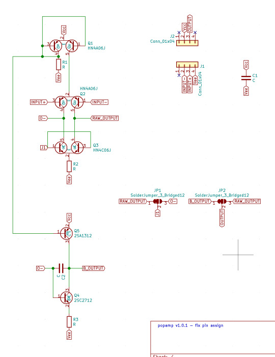
この要件を目指してNJM4580の等価回路を元にシミュレーションで検討を行ったところ、差動増幅回路の後ろにエミッタ接地増幅回路+定電流回路を使った能動負荷という構成で十分に達成できることが分かりました。次の回路図がシミュレーションに使用したものです。

ここでは電源電圧を±9Vとし、入力信号として振幅±0.1mV(100μV)の三角波を入力しています。このときの出力波形の振幅は負荷抵抗が100kΩ時でおよそ±3.9V、10kΩ時でおよそ±450mV、1kΩ時には±45mVとなりました。増幅率としてはそれぞれ39000倍、4500倍、450倍となります。
この回路でボルテージフォロワ回路を構成すると、入力信号の振幅が±3Vの場合は40kΩ程度までの負荷抵抗なら問題なく動作するようです。負荷抵抗を10kΩとすると、入力信号の振幅は±0.8V程度が限界のようでした。また、消費電力は0.205mA程度でした。
なお、この回路では後段のエミッタ接地回路部分に流す電流を大きくすることで、出力電流を増やすことができ、より小さい負荷抵抗でも動作させることができます。これは、カレントミラー回路に接続されている抵抗(回路図ではR3)の値を小さくするだけで対応できます。たとえばR3を10分の1の値である10kΩに変更すると、負荷抵抗10kΩ、入力信号の振幅±3Vでもボルテージフォロワとして正しく動作します。ただしそうすると消費電流は単純に10倍、約2mAに増加します。
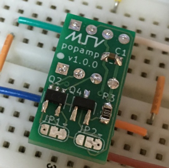
実装
回路構成が見えてきたので、これを実際の基板に起こしていきます。カレントミラー回路や差動増幅回路では、使用するトランジスタのペアの特性が揃っている必要があります。これは、1素子に2つのトランジスタが封入されているデュアルトランジスタを利用することで簡単に解決できます。今回はPNPトランジスタとしてHN4A06J、NPNトランジスタとしてHN4C06Jを使用しました。
特性が揃っていることが重要なので、増幅率(ランク)はどれでも問題ありません。また、エミッタ接地増幅回路側の定電流回路にはHN4A06Jとなんとなく特性が似ていそうな2SA1312を、増幅用トランジスタには2SC2712を使用しました。増幅用トランジスタは2SC3324等、適当なものでも問題ないと思います。
出力端子は1回路入りオペアンプで一般的に使われている配置と同じに設定しました。また、さらに消費電力を減らしたい場合に向け、ハンダジャンパ端子(JP1とJP2)を設置して、簡単な加工でエミッタ設置増幅回路をバイパスできるようにしています。具体的にはQ5を接続せず、JP1、2の1-2間配線をカットして2-3間をハンダでショートさせることで、差動増幅回路の出力をそのまま取り出せるようになります(ただ、この構成では取り出せる電流がさらに小さくなるため、かなり限定された回路でしか使えなくなるかと思います)。
最終的な回路は次のようになっています。
この回路を本物の1回路入りオペアンプと同じサイズに実装したかったのですが、チップ部品を使っているとはいえ流石にそれは難しく、最終的には約2倍の面積の11×21mmサイズの基板に収める形にしました。ピン間隔はオペアンプと同じなので、既存製品との差し替えも周囲にスペースがある限りは容易です。

基板発注
基板の製造はおなじみElecrowに発注しました。製造できる基板の最小サイズについては記載がなかったので若干心配ではありましたが、何事もなく製造されて届きました。基板の切断面を見たところ、Elecrow側で面付けして製造されたようです。表面実装部品を使っていますが、0.95mmピッチなので半田付けも難しくはありません。一番面倒くさかったのは足となるリードフレームの半田付けでした。これどうやって半田付けするのが正解なんでしょうね……。
そんなわけで完成したものが、こちらのものになります。
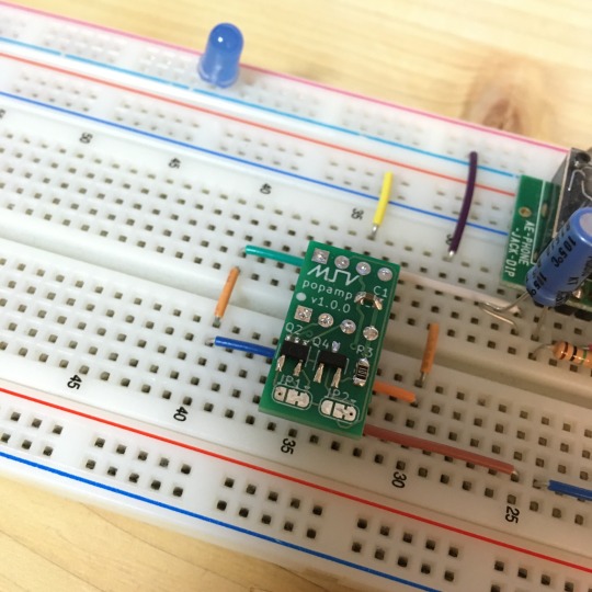
特性チェック
これで本当にオペアンプとして動作しているのか、ボルテージフォロワを使ったバッファ回路を作って簡単にチェックしてみました。電源電圧は9Vの単電源で、入力信号に対しコンデンサを挟んで分圧した電圧(4.5V)を加えて増幅し、出力段にもコンデンサを挟んで直流成分をカットするというよくある回路です。

設計的にはラインレベルの信号であれば問題なく���ッファできるはずなので、まずはAbleton LiveのIR Measurement DeviceとSpectrumメータを使って正弦波のスイープを行い、簡単に周波数特性をチェックしてみました。また、比較対象としてADA4084-1ARZを使った回路でも同じように測定を行なっています。次の上のグラフが自作オペアンプの測定結果、真ん中のグラフがADA4084の測定結果で、下のグラフがAbleton Liveからの出力です。

スイープする周波数は一定速度で変わっていくため、見かけ上高域ほど強度が下がるように見えますが、Ableton Liveからの出力と、バッファ回路からの出力でほぼ同じ変化になっているため、少なくとも22kHz程度までの範囲であればほぼフラットな周波数特性になっていると思われます。
ノイズレベルに関しては調査が難しいのですが、オーディオインターフェイスのLINE入力ゲインを最大にした状態で、入力をGNDに落とした状態での出力を測定することで簡易的に見てみました。次の上のグラフが自作オペアンプの測定結果、真ん中のグラフがADA4084の測定結果です。

どちらも100Hz以上のノイズ成分は最大-84dB程度で、あまり違いは見られません。50Hzや100Hzにピークがあるのは家庭用交流電源が発する電磁波を拾っているものと思われるため、このあたりのノイズ成分の評価は難しいところです。
また、PC接続型のオシロスコープ+ファンクションジェネレータを使い、三角波をこのバッファ回路に入れた際の出力をチェックしてみました。図は緑が入力、赤が出力で、100Hzの信号を入力した際の結果です。入力と出力がほぼ一致していることが分かります。周波数を変えていくつか試してみましたが、いずれも入力とほぼ同じ波形が出力されました。

ちなみに、消費電流は0.075mAほどでした。
耳で評価は難しい
ということで作ってみたオペアンプですが、小信号のバッファ回路で使用する場合、少なくとも自分の耳では今のところ違いが分かりません。思っていた以上に良くできていて我ながらびっくりです。前述のように限られた条件下でのみ動作するものなので、汎用性では一般的なオペアンプには及ばないとは思いますが、皆様もオペアンプを作って楽しんでみてはいかがでしょうか。
6 notes
·
View notes
Text
Casio DG-10 MIDI out mod
Should’ve blogged this years ago. People email me about once a month asking for details and I reply with the following - don’t really have time to rewrite it or nicely format it right now, so I’ll just paste it as-is:

If you check the last comment on this Instagram post ( https://instagram.com/p/xjomIjq_pq/ ), that should get you started - if you reached me via Tumblr, you might not've seen those comments... But I never got around to doing a full Tumblr post about it, so thanks for reminding me! It'll be a while yet before I find the time to make some diagrams, take some photos etc, but if you feel comfortable cracking open your DG-10 and poking around, you'll find that everything's fairly clearly laid out. You'll need to carefully unpack all the circuitboards and cardboard insulation layers, and the CPU's quite a fanny-on to access, but this doc will tell you exactly which one you should be looking for: http://www.warningwillrobinson.com.au/manuals/Casio%20DG10%20DG20%20service%20manual.pdf It's worth having a multimeter handy so you can double-check my instructions: the gist is that when you're playing notes on the guitar (which'll involve a bit of precarious finger acrobatics - I recommend laying the sections of the guitar on your lap for this) you should get corresponding spikes on the multimeter when it's touching pins 17 and GND. I crashed the DG-10 a few times by raking the wrong pins while confirming the info in the manual, but I found that pin 17 has to be counted from pin 1 on the top right going downwards. They then go from 32 on the bottom left up to 64 at the top. This is from the BACK of the CPU's board, where the soldered points are - and up/down are relative to the orientation of the board when you've got the guitar strings-down on your knees with the neck pointed out to your left, and the exposed board lifted up so it's accessible. Might not've explained that very well, but the worst I was able to do was crash the thing and have to replace the batteries to start it again. So once you've found the right pins, and ideally checked them by attaching some alligator clips/similar to a DIN-5 MIDI cable (be careful you don't short anything and wreck your MIDI interface! Most are pretty well protected and I've never ruined one, but there's a first time for everything - I accept no responsibility blah blah blah :), you're ready to solder a DIN-5 jack. MIDI is a unidirectional serial signal, so at its bare minimum it only needs two contacts - data and ground. DIN-5 MIDI normally just uses 2 or 3 of the available pins. Now...it's been a while, and I can't remember which two I soldered to on the jack...but I do remember that I found a bunch of conflicting pinout diagrams (most of which don't make much effort to specify whether they're showing the pins as viewed from the front or back of a jack) and had to resolder and swap the wires until I got it right. A few miniutes' googling will probably set you straight, though. Beyond that, it was just a case of Dremelling the hole and screwing in the jack's mounting plate as you can see here: https://instagram.com/p/xp_Z7Zq_oG/ Another caveat: proper MIDI circuits have various types of spike/ground-loop protection, with diodes and things in, but I don't really know much about that... This is a bit rough and ready, but I haven't experienced any problems and it's thus far been solid enough for occasional studio use either into a DAW or controlling a hardware synth directly. -------------------------- As for other mods, the only one I did was hijacking the 'string mute' button for an always-on option with a switch - also visible in that last pic. It's not much use, to be honest. I *was* a bit miffed to discover that while the DG-10's internals are almost identical to those of the DG-20, I couldn't find a way of accessing those basic synth parameter options detailed in the PDF on the DG-10 despite extensive probing. If you discover anything yourself, I'd be keen to hear about it! -------------------------- I've just realised that I complicated matters by saying you only use two pins; of course, you use the three pins that you've listed :) +5 from 64, ground from wherever you find it (though I used 32), and MIDI from 17. Other tantalising pins on that CPU purport to control chorus, chorus speed, chorus depth, and distortion, and one says it switches between DG-10 and DG-20 mode, but I couldn't get them to do anything... Having built-in chorus on this would be amazing, though, and the only hardware difference I've been able to establish between the 10 and the 20 is the MIDI output assembly, the membrane patch control and the drum pads on the top. Frustrating to know the potential is there...maybe I can persuade a more technically-adept friend to look into it for me. I'll let you know if I find anything! As for wiring those 3 pins, let's number the MIDI jack pins from 1-5 where 1 is the uppermost in these photos - ie on the far left if you were inside the case looking out through the jack hole: GND goes from pin 32 on CPU to pin 2 on the rear of the MIDI jack (black in the photos) MIDI goes from pin 17 on CPU to pin 3 on the rear of the MIDI jack (red in the photos) +5v goes from pin 64 to on CPU to pin 4 on rear of MIDI jack (also black in photos - I only had red and black wire)
#casio#casiodg10#dg10#casioguitar#electronicguitar#midiguitar#keytar#80s#synth#guitarsynth#synthesizer#diy#hardwarehacking
9 notes
·
View notes
Text

mini Sparkle Motion prototype - a tiny, fully-featured WLED board ✨🔌📏💡🌈
We're doing a lot of serious testing with our WLED mega-board, code-name Sparkle Motion .
While doing some holiday lighting projects, we also wanted something slim enough to slip into any design. It still uses an ESP32 for the best support, with USB-serial programming, 5A fuse, 5V level shifting + 100 ohm series resistors for pixel drivers, user/reset buttons, a user LED and onboard neopixel, JST SH analog/digital connector, QT I2C connector, 4 GPIO plus power/ground breakouts, and USB type C power/data input.
However, this version is made simpler and less expensive by dropping the DC jack and USB PD support: it's only for 5V strips if you want to power them directly (you could still drive 12V or 24V pixels, but you'll need separate power for them). Instead of a full set of terminal blocks for 3 signals, we only have two outputs, and they have to share the power and ground pins. It could also be used for a single two-pin dotstar LED setup. We kept the built-in I2S mic but dropped the on-board IR sensor - if you want an IR sensor, you'll be able to plug it into the JST SH port with a simple cable or solder it into the breakout pads.
The trade-off is that it's much smaller and slimmer, especially when no terminal blocks are soldered in by default: only 1.2" long x 0.785" wide (~1 sq in) x 0.3" thick vs. the original's 2" x 1.3" (2.6 sq in) x 0.55". To get it that small, we went 4-layer to give us a nice big ground and 5V plane in the middle and double-sided assembly. Coming soon.
#sparklemotion#wled#esp32#neopixel#holidaylighting#ledprojects#makers#electronics#prototyping#hardwaredesign#usbtypec#qtconnector#gpio#micromaker#slimdesign#techinnovation#ledcontroller#openhardware#adafruit#diylighting#iotprojects#esp32projects#compactdesign#ledenthusiast#holidaydecor#iotmaker#makercommunity#hardwarehacks#tinytech#ledlights
30 notes
·
View notes
Text
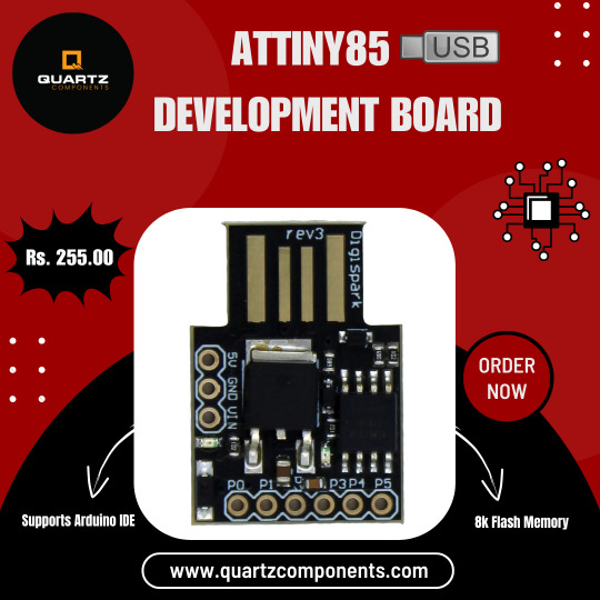
You can purchase the ATTINY85 USB Development Board for just Rs. 255.00 on quartzcomponents.com. This affordable and versatile development board is perfect for your microcontroller projects. It features an ATTINY85 microcontroller and USB connectivity, making it a cost-effective choice for DIY electronics enthusiasts and hobbyists. Don't miss out on this great deal for your electronics projects!
#attiny85#usb#developmentboard#microcontrollerprojects#diyelectronics#makercommunity#embeddedsystems#hardwarehacking#opensourcehardware#arduinoprojects#embeddedprogramming#circuitdesign#techinnovation#gadgetgeek#prototyping#electroniccomponents#electricalsky#electricalprojects#electricalwires#electricalengineers
2 notes
·
View notes
Text
Introduction
Khanu India is one of the largest IT distributors in India and one of the best sellers in India. We are able to provide IT related things like Desktops, Laptops, Printers, TV’s and other IT Related Components with stunning cheap price comparatively then others.
We have good knowledge and experience and have been doing this almost 18 years locally without any negative feedback. Now we are entering into the digital world and doing very well. Our Company started in 2003 at Tirupur as a small startup at the time we are supplying IT Products to the IT Companies Then a small idea to turn this into an E-Commerce Company and has a good move. We are growing like a rocket into the sky.
Now we have a Large Warehouse and Distributing Office with almost 10 employers working here now. With your grace we will grow more and give most spectacular offers ever you seen before
Our Best

We are authorized as a highly Professional E-commerce Company and we perfectly do Wholesale, Retail, Marketing, and distributing to sub dealers and retail shops. We highly follow strict rules for considering “Quality”.
We believe Quality is the best thing to serve to the customers and we make sure that’s keep going in any situation. Wants to make sure people have a full satisfaction with their products and give a simple service and guarantees to make a pleasant relationship with them. That’s the point to take our Business into making a Potential impact in Indian E-Commerce market.
Mission
Make Sure Our Customers are Satisfied to buy our product and build a relationship with them lifelong and give quality material to the working environment so we need to make sure ourselves not a problem for IT companies.
Furthermore, Wanna develop a market in this niche to make sure our good quality goanna reaches each and every person who needs a perfect IT Equipment in the overall country.
Provide Excellent Marketing Services to the customer never seen before in any other companies that could be a good reflection to our company at most we think.

Looking for a close environment for the sub dealers and retailers to make sure we can give a good proposal for their investment and give good content to the people as end users because we know the end user’s reaction when they receive low quality products and don't get satisfied with their shop. Our Main achievement is to prevent that from gonna happen.
Vision
Giving a good purchasing experience to the customers is our main goal. We will not compromise with quality things. Another thing is to get a good experience as an E-Commerce company from Provider to customer.
Our idea to get ground level experience for sales and marketing for those products to develop ourselves as well as so. Keep seeking for the best product available in the market to satisfy people to buy a good product on their budget price so they don’t get scammed by any other poor products.

#hardware#hardwarestore#hardwarestores#hardwarewallet#hardwareonly#hardwarekomputer#hardwarejakarta#hardwaresociete#hardwaredesign#hardwarelane#hardwareporn#hardwareengineering#hardwares#hardwarehacker#hardwareux#hardwaremusic#hardwareelectronicmusic#hardwaregallery#hardwarecrush#hardwarestorefinds#hardwarehacking#hardwarecity#hardwarerepair#hardwareinstall#hardwareunboxed#HardwareDeveloper#hardwarerender#hardwareshop#HardwarePlus#hardwarequality
0 notes
Photo

Install from repository @bernadsuper #pentester #kalilinux #ethicalhacker #hardwarehacker #codinglife #python #ubuntu #ubuntumaniac #hacking #hacker #programmer #Programming #coding #coder #computer #penetrationtesting #setup (at DKI Jakarta, Indonesia) https://www.instagram.com/p/CACkMm3B5RG/?igshid=2f614nxqhxw9
#pentester#kalilinux#ethicalhacker#hardwarehacker#codinglife#python#ubuntu#ubuntumaniac#hacking#hacker#programmer#programming#coding#coder#computer#penetrationtesting#setup
0 notes
Photo

Testing... #synth #diy #sdiy #analogsynth #synthdiy #circuitbending #electronics #hardwarehacking #ekkoflok #noteurorack #exsoso #soundart #contemporaryart — view on Instagram https://ift.tt/36WZMjR
3 notes
·
View notes
Photo

Power delivery circuit inside the light panel #diy #tech #hardware #hardwarehacking #reverseengineering #lighting #videoproduction #electronics #makersgonnamake #nerdlife
#videoproduction#lighting#hardware#diy#hardwarehacking#makersgonnamake#electronics#nerdlife#reverseengineering#tech
2 notes
·
View notes
Photo

I2C Sniffing - András Tevesz shows How to Listen to Your Arduino’s I2C Bus 😍👍👏 #HardwareHack #Arduino #Coding #Electronics
Know More - https://bit.ly/3DXKyNx
1 note
·
View note
Text
スイッチ付きボリュームポット(可変抵抗器)の研究と改造
音響機材関係でぼちぼち使われる部品として、スイッチ付きのボリュームポット(可変抵抗器)というものがあります。ポットとスイッチが一体化されており、軸部分を押したり引いたりすることでスイッチをON/OFFできるというものです。これを分解して抵抗部分の容量を変えてみる工作をしてみました。

スイッチ付きボリュームポットにはいくつかの種類がありますが、エレキギター/ベースで一般的に使われているのは上の写真のようなものです。一般的なボリュームポットの下側にスイッチがくっついており、軸の先がスイッチ部分に接続されている構造となっています。
こういったボリュームポット自体は比較的容易に購入できますが、抵抗値の選択肢は限られており、500Kもしくは250KのAカーブもしくはBカーブ以外のものはあまり流通していないようです。
��かし、ここで見て分かるとおり、上側(ポット部分)は一般的なポットと同じ形をしています。そこで、この部分を別のものに差し替えることで抵抗値を別の物に変えることができないか調べてみました。
まずはスイッチ部分とポット部分の分離作業ですが、こちらは曲がったツメの部分を伸ばしてやるだけで簡単に行えます。

スイッチ部分には溝があり、ここにポットの軸を入れる形になっているので簡単に取り外せます。

また、ポット部分は同様に軸側のツメを伸ばしてやることでこちらも簡単に分解できます。ちなみに自分はこの作業に写真のgoot製のピンセット(TS-13)を使いました。

分解後、上側の基板を別途調達したALPHA製の同型ポットの基板と比較したのがこの写真です。上側がALPHAのポットの基板、下側がスイッチ付きポットの基板です。見て分かるとおり、穴の径が違います……。そのため、これらを単純に差し替えるだけではうまく軸が回りませんでした。

一方、LINKMAN製のポットの基板はは形状や穴の径が(完全に同じではないですが)似ています(写真右)。こちらに差し替えたところ、多少ガリは出るもののボリュームポットとして動作することを確認できました。

ちなみに、後日ALPHAの刻印入りのスイッチ付きポット(下の写真の真ん中のもの)を入手して比較してみたところ、こちらはALPHA製のポットと完全に基板サイズが同じで差し替えが可能になっていました。

最初に分解したものもALPHA製とうたわれていたのですが、本体にはALPHAのロゴはありませんし、ALPHAの製品一覧からも見つかりませんでした。ALPHAロゴ入りのもののほうが次の写真のように部品点数がちょっとだけ多く、コストがかかっているような感じがするので、ロゴなしのほうは旧版なのか、廉価版なのかもしれません。

1 note
·
View note