#Can arduino be used to control a forward and reverse motor
Explore tagged Tumblr posts
Visit Tumblr Blog
Explore Tumblr blogs with no restrictions, modern design and the best experience.
Last Seen Tumblr Blogs


Fun Fact
US Tumblr user growth rate is estimated to slow down to 4.1%.
Text
Can arduino be used to control a forward and reverse motor

#Can arduino be used to control a forward and reverse motor how to
#Can arduino be used to control a forward and reverse motor driver
#Can arduino be used to control a forward and reverse motor pro
Our priority is making something that works, so we are using rubber bands to fix the motor. The motor and driveshaft can be connected directly. Pic 4: Setting the pinion gear onto the LEGO gear We want to keep the motor as small as possible, so let’s keep trying! If you have a LEGO motor, that may work too. This is a DC motor, but there was an article about making a motor and a LEGO gear by yourself using a Pinion gear from Mini-4WD, so we will use this method to connect the motor with a LEGO gear. The steering part is done, so let’s go into the drive shaft. Pic 3: Steering parts (left: backside/right: without tires)Ĭreating the Drive Shaft for the Forward/Backward Movement Today, we want to keep it as small as possible, so here is what we made.
#Can arduino be used to control a forward and reverse motor how to
If you search “LEGO steering”, there are many pages showing how to mount a LEGO steering. So, today, let’s use LEGO blocks to fulfill “The body should be easy to build”. Let’s think about what we need for a steering system and try them out. I’d like to say, “We’re going to make a realistic one using a 3D printer!”, but at this point that is too difficult. Now that we have the circuit ready and that we are able to control the angle of the motor with a servo motor, let’s create the steering for the car. Next, let’s make it so that we can control it based on the input from the controller. In this example, we set the delay at (1500), so the steering and driveshaft will move every 1.5 seconds. Pic 2: Controlling a servo motor with Arduinoįigure 3: Arduino circuit for servo motor We will control the servo motor using this servo library. When using a servo motor with Arduino, there is a library of useful materials (set program with pre-made process). Let’s create a circuit to control the servo motor. The servo motor we will be using today can control the angle from 0 to 180. What Is a Servo Motor?Ī servo motor is like the other motors we’ve used before with an additional circuit that controls angles. If we use a DC motor, can we make it turn by 30 degrees to the right? Maybe we should rotate the motor for just a little bit and move the motor 30 degrees? Sounds pretty difficult. Let’s think about mounting the steering to make the car turn left and right. We can use the same idea to make the RC car go forward and backward. In the circuit in figure 2 (see article “ Use Arduino to Control a Motor Part 2“), we can rotate and reverse the motor by outputting signals from Arduino #9 and #10, one after the other. We went over forward/backward motor movement in the article “Use Arduino to Control a Motor Part 2”.
#Can arduino be used to control a forward and reverse motor driver
Going forward and backward using a motor driver First, we will design the heart of an RC car, the circuit for “Basic movements are forward, backward, and steering mount.” Today, we will learn about many new concepts. > If we use infrared or XBEE wireless module, it may be possible, but it will be quite difficult. Let’s think about making the battery small too. > The Arduino UNO is pretty big to begin with, so maybe we should use a different Arduino. > We can use LEGO blocks, so that it will be easily to modify it. > We need 2 motors, one for going forward and backward, and one for the steering. Now, let’s see what kind of technology we need to use to make these things possible… Basic movements are forward, backward, and steering mount.Deciding the Specs of the RC Carīefore we get started, let’s decide the overall specs for the RC car. We will go over how all these parts work and how to customize them using actual demonstrations. In other words, if you fulfill these functions, you can call it an RC car. Today, we will try to make the basic parts of an RC car by ourselves and study basics about electronic circuits, steering, and engine movements.įigure 1: Structure of a radio-controlled carįigure 1 shows a rough breakdown of the functions found in an RC car.
#Can arduino be used to control a forward and reverse motor pro
Today Electronic’s RecipeĪrduino Pro mini (Arduino Pro Mini 328 5V 16MHz)īox for AA batteries (series circuit for 4) Just like when we made the Stevenson Screen, we will decide the specs of the radio-controlled car before getting started. Today, we will look at the motor driver in more detail and make our own radio-controlled car using a motor driver. In the article “ Use Arduino to Control a Motor Part 2“, we went over how to use a motor driver.
0 notes
Text
4-Wheel Arduino-Controlled Robot
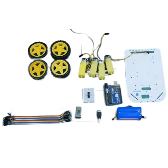
Dabble-controlled 4-wheel robot — an easy-to-build and easy-to-control robot that can be controlled via Bluetooth using Dabble, an indigenously developed mobile application. An Arduino Uno board,4WD Four Wheel Drive Kit — A Smart Robot Car with Chassis and other accessories and tools are all you need to build your robot. To control it, download Dabble from Google Play and pair it with Bluetooth; then your robot is ready to go!
Components Required:
4WD Four Wheel Drive Kit — A Smart Robot Car with Chassis Arduino UNO Breadboard HC-05 Bluetooth Module Jumper wires Motor driver DC Terminal Block Motor Mounts
Connection:
To begin, we will construct the body of the 4 Wheel Robot.
Take the chassis and flip it over. Mount four motor mounts to this chassis with M3 bolts and nuts. M2 Nuts and Bolts are used to secure the DC Motors to the motor mounts. Attach wheels to the DC Motor’s shafts. As a result of flipping the assembly, your body is created. The microcontroller we’ll be using is the Arduino Uno. We will make all of the connections on it, but we will also use a breadboard to make the connections.
Make the connection shown in the diagram below.
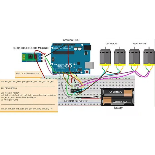
Because the Arduino Uno does not have enough power to run four motors, we will use motor drivers. As a result of adding the motor driver, we will be able to provide the robot’s needed energy.
The left two motors are connected in parallel. Similarly, the right two motors are too connected in parallel. The connections are made as follows:
Enable Pins — Digital Pin 10 and 11
VCC — Arduino 5V
m1_dir1, m1_dir2, m2_dir1, m2_dir2 — Digital Pin 4, 5, 6, and 7
VC — External Battery
GND — GND of Arduino and Battery make sure we connect all the GND wires.
Then we need to add a module that will connect your robot to the Dabble App on your smartphone.
We’re using the Bluetooth HC05 Module. Connect it
Our robot will require an additional power source. In addition, we will use a DC Terminal Block or a DC Jack to connect the Arduino Uno to the battery.
Arduino Code
Upload the following code: code for arduino
Working
Using Dabble, we can easily connect our robot to our Smartphone.
You must connect the Bluetooth that you are working on before you can work with any of the modules.
There are numerous modules available in the App for additional functionality.
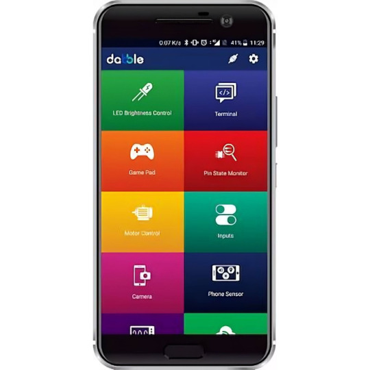
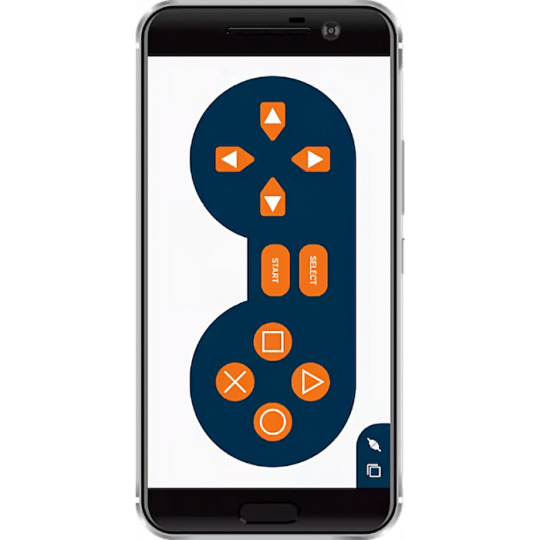
We’ll be working with the Gamepad Module today.
And we’ll be using the buttons on the left:
Move Forward — Move Up Down — Reverse Direction Left — Turn Left Right — Turn Right
Your DIY Dabble-controlled 4wheel robot is now ready for action!
0 notes
Video
tumblr
Lets get some code on this thing
So now we have the electronics sorted, lets have a look at the code. I’m borrowing heavily from this resource. I chose to use this code since the project was very well documented with some nice videos. The code also uses the same gyroscope as me. One downside is that this code is designed for stepper motors and I’m using cheap DC motors.
Before I jumped into the main code, I created a quick script just to check the motors were working. I created a few functions and ran them to ensure the motors moved correctly. If you look at this code you can also see how I am using the input pins of the motor driver to set direction and the enable pin with PWM to set the speed.
/* * Drive Motors with an Arduino Mini Pro using an L239D 'H' bridge * Keith Ellis * July 2018 * */ #define motor_left_A 2 // Motor Left Pin A - High = forward #define motor_left_B 4 // Motor Left Pin B - High = reverse #define motor_left_En 3 // Motor Left Enable Pin, PWM on this pin will control speed #define motor_right_A 5 // Motor Right Pin A - High = forward #define motor_right_B 7 // Motor Right Pin B - High = reverse #define motor_right_En 6 // Motor Right Enable Pin, PWM on this pin will control speed void setup() { pinMode(motor_left_A, OUTPUT); pinMode(motor_left_B, OUTPUT); pinMode(motor_left_En, OUTPUT); pinMode(motor_right_A, OUTPUT); pinMode(motor_right_B, OUTPUT); pinMode(motor_right_En, OUTPUT); } void loop() { AllMotorsFwd(127); // Speed from 0 - 255 delay(100); AllMotorsRev(255); delay(75); AllMotorsFwd(127); delay(100); AllMotorsRev(255); delay(120); AllMotorsFwd(127); delay(50); AllMotorsRev(255); delay(75); AllMotorsFwd(127); delay(100); AllMotorsRev(127); delay(125); } void LeftMotorFwd(int speed){ //Speed is int from 0 - 255 digitalWrite(motor_left_A, HIGH); digitalWrite(motor_left_B, LOW); analogWrite(motor_left_En, speed); } void LeftMotorRev(int speed){ //Speed is int from 0 - 255 digitalWrite(motor_left_A, LOW); digitalWrite(motor_left_B, HIGH); analogWrite(motor_left_En, speed); } void RightMotorFwd(int speed){ //Speed is int from 0 - 255 digitalWrite(motor_right_A, HIGH); digitalWrite(motor_right_B, LOW); analogWrite(motor_right_En, speed); } void RightMotorRev(int speed){ //Speed is int from 0 - 255 digitalWrite(motor_right_A, LOW); digitalWrite(motor_right_B, HIGH); analogWrite(motor_right_En, speed); } void AllMotorsFwd(int speed){ //Speed is int from 0 - 255 LeftMotorFwd(speed); RightMotorFwd(speed); } void AllMotorsRev(int speed){ //Speed is int from 0 - 255 LeftMotorRev(speed); RightMotorRev(speed); } void LeftMotorStop(void){ digitalWrite(motor_left_A, LOW); digitalWrite(motor_left_B, LOW); digitalWrite(motor_left_En, LOW); } void RightMotorStop(void){ digitalWrite(motor_right_A, LOW); digitalWrite(motor_right_B, LOW); digitalWrite(motor_right_En, LOW); } void AllMotorsStop(void){ LeftMotorStop(); RightMotorStop(); }
This worked as planned, you can download this code here
After editing the Balance Bot code to take out references to the stepped motors and copying in my motor functions I ended up with the code here.
Before running this code, the balance point of the robot needs to be determined. This can be done by running the calibration code here Balnce the robot upright and open the serial console. Make a note of the Balance value and paste it into the variable acc_calibration_value on line 17 of the main Balance_robot.ino code.
After messing about with the PID variables I managed to get the robot balancing of sorts as seen above. To tune the PID values I used this video here. I was well chuffed, but it is far from perfect. I’ll leave this post here for now, my next post will run through PID tuning and weight placement.
5 notes
·
View notes
Text
L298N Set-up with Arduino Hardware --- Robotics
Completed the set-up of a L298N chip and its interface with an Arduino Uno board.
The layout is quite simple: ENA and ENB are both connected to two analog ports in Arduino. These ports receive Pulse-Width Modulated signal from the board and adjusts the electrical signals in OUT1 ~ 4 accordingly. If I’m ever going to control them with a joystick or potentiometer, I’ll have to map the input range of these additional peripherals to the standard of these PWM ports. By placing Arduino in between the potentiometer, connected to on-board ground and 5V output, I should be able to modulate the speed of the motors.
Now that the PWM ports are out of the way, I continued to work on ports that control the direction of motors.
Basically, each motor is assigned two IN ports whose pattern of currents controls the direction: IN1 ~ HIGH and IN2 ~ LOW can be forward while IN1 ~ LOW and IN2 ~ HIGH can be backward. The principle behind this is the H-bridge pattern within L298N: the upper portion of the “I” in the left side of “H” and the lower portion of the “I” on the right side of “H”, connected in the middle by the “-” portion of “H” create a pattern with, let’s say, a low voltage on the left side and a high voltage on the right(depending on the direction of the current). Reversing this pattern can cause the voltage to be high on the right side and low on the left side. This allows L298N to control the motor’s direction.
That’s where Arduino fits in, since it allows the board to output a certain pattern of electrical signals, controlled by the programmer. Thus, I used jump wires to connect four Arduino pins with the IN ports, from IN1 to IN4. I’m unable to find a way to force Uno to receive commands from the keyboard without modifying it. But a potential way to do so is to utilize HID libraries on Github to rewrite the board and forcefully insert a renewed binary(which, essentially, forces Uno to behave like Leopard and can possibly weak havoc). Thus, I’ll use a Bluetooth module instead and connect it to a custom virtual joystick on my cell phone.

Then comes the motors, the most essential part of this project. I plan to use at least two 6~9V TT DC motors for a functioning robot. In addition, most industry-level motors are 12V+, which means that external power source is necessary. Recall that Arduino Uno only supports a voltage of 5V-, and each pin can only support a maximum of 50MA with a total limit of 200MA for all pins. So what we often do is to attach a battery box’s power wire to the VCC terminal in L298N, while the ground wire connects to the GND terminal along with another wire that’s connected to Arduino’s GND pin.

Then comes the code. To summarize, I set every connected pin’s mode to OUTPUT, including IN1 ~ 4 and ENA/B, and then created a function that alters the pins’ values according to the intended direction of movement. I will probably publish the code once the whole project is done.
The next steps:
Connect the Bluetooth module to the circuit
Finish the custom app(aka the virtual joystick)
Finish the vessel’s main body with cardboard materials
Add support for app and Bluetooth in the code
Ground trial!
0 notes
Text
OBSTACLE AVOIDING ROBOT

INTRODUCTION :
An Obstacle Avoiding Robot is a type of autonomous mobile robot that avoids collision with unexpected obstacles. In this project, an Obstacle Avoiding Robot is designed. It is an Arduino based robot that uses Ultrasonic range finder sensors to avoid collisions.
MATERIALS REQUIRED:
· Arduino NANO or Uno (any version)
· HC-SR04 Ultrasonic Sensor.
· LM298N Motor Driver Module.
· 4 BO Motors.
· Battery.
· Wheels.
· Chassis.
· Jumper Wires.
· Servo motor
BRIEF DESCRIPTION ON THE PROJECT:
In the above figure, Arduino is the main processing unit of the robot. Out of the 14 available digital I/O pins, 7 pins are used in this project design.
The ultrasonic sensor has 4 pins: Vcc, Trig, Echo and Gnd. Vcc and Gnd are connected to the +5v and GND pins of the Arduino. Trig (Trigger) is connected to the 9th pin and Echo is connected to 8th pin of the Arduino UNO respectively.
A Servo Motor is used to rotate the Ultrasonic Sensor to scan for obstacles. It has three pins namely Control, VCC and GND. The Servo Control Pin is connected to pin 11 of Arduino while the VCC and GND are connected to +5V and GND.
L293D is a 16 pin IC. Pins 1 and 9 are the enable pins. These pins are connected to +5V. Pins 2 and 7 are control inputs from microcontroller for first motor. They are connected to pins 6 and 7 of Arduino respectively.
Similarly, pins 10 and 15 are control inputs from microcontroller for second motor. They are connected to pins 5 and 4 of Arduino. Pins 4, 5, 12 and 13 of L293D are ground pins and are connected to Gnd.
First motor (consider this as the motor for left wheel) is connected across the pins 3 and 6 of L293D. The second motor, which acts as the right wheel motor, is connected to 11 and 14 pins of L293D.
The 16th pin of L293D is Vcc1. This is connected to +5V. The 8th pins is Vcc2. This is the motor supply voltage. This can be connected anywhere between 4.7V and 36V. In this project, pin 8 if L293D is connected to +5V supply.
WORKING PRINCIPLE:
Before going to working of the project, it is important to understand how the ultrasonic sensor works. The basic principle behind the working of ultrasonic sensor is as follows:
Using an external trigger signal, the Trig pin on ultrasonic sensor is made logic high for at least 10µs. A sonic burst from the transmitter module is sent. This consists of 8 pulses of 40 KHz.
The signals return back after hitting a surface and the receiver detects this signal. The Echo pin is high from the time of sending the signal and receiving it. This time can be converted to distance using appropriate calculations.
The aim of this project is to implement an obstacle avoiding robot using ultrasonic sensor and Arduino. All the connections are made as per the circuit diagram. The working of the project is explained below.
When the robot is powered on, both the motors of the robot will run normally and the robot moves forward. During this time, the ultrasonic sensor continuously calculates the distance between the robot and the reflective surface.
This information is processed by the Arduino. If the distance between the robot and the obstacle is less than 15cm, the Robot stops and scans in left and right directions for new distance using Servo Motor and Ultrasonic Sensor. If the distance towards the left side is more than that of the right side, the robot will prepare for a left turn. But first, it backs up a little bit and then activates the Left Wheel Motor in reversed in direction.
Similarly, if the right distance is more than that of the left distance, the Robot prepares right rotation. This process continues forever and the robot keeps on moving without hitting any obstacle.
APPLICATION OF THIS CONCEPT:
· Obstacle avoiding robots can be used in almost all mobile robot navigation systems.
· They can be used for household work like automatic vacuum cleaning.
· They can also be used in dangerous environments, where human penetration could be fatal
0 notes
Text
The Arduino Hits The Rails
Tweet
Certain hobbies come in clusters. It isn’t uncommon to see, for example, ham radio operators that are private pilots. Programmers who are musicians. Electronics people who build model trains. This last seems like a great fit since you can do lots of interesting things with simple electronics and small-scale trains. [Jimmy] at the aptly-named DIY and Digital Railroad channel has several videos on integrating railroad setups with Arduino. These range from building a DCC system for about $45 (see below) to a crossing signal.
There are actually quite a few basic Arduino videos on the channel, although most of them are aimed at beginners. However, the DCC — Digital Command and Control — might be new to you if you are a train neophyte. DCC is a standard defined by the National Model Railroad Association.
Model trains pick up electrical power from the rails. DCC allows digital messages to also ride the rail. The signal shifts from positive to negative to indicate marks and spaces. By diode switching the electrical signal, the train or other equipment can get a constant supply of current. However, equipment monitoring the line ahead of the diodes can read the data and interpret it as commands.
To accommodate old equipment, you can stretch the high or low values to make the average voltage either positive (forward) or negative (reverse). This can heat up DC motors, though, so it may shorten the life of the legacy equipment.
The build uses an available Arduino library, so if you want to get into the protocol you’ll have to work through that code. We had to wonder if there were other places where passing power and data on the same lines might be useful. There are other ways to do that, of course, but this would be a reasonable place to start if you needed that capability.
If you want to use an mBed system instead of an Arduino, there’s a great tutorial for that. Either way, it is just the thing for your next coffee table.
youtube
Bookmark It
Hide Sites
$$('div.d').each( function(e) { e.visualEffect('slide_up',{duration:0.5}) });
The Arduino Hits The Rails was originally published on PlanetArduino
0 notes
Video
tumblr


Voice Control Car
Description of Project
The aim of this project is simply to design voice control car via Bluetooth. However, there are several commands in this project such as “go ahead”, “go back”, “turn left”, “turn right” and “stop” commands. But, I have only managed to get “Turn left” command work so far. In the beginning of this project I have managed to operate all the commands, but then it stopped working for some reasons. From my understanding I used wrong type of power and I may have burnt something in this project. So, this might be why it stopped working. On the other side, the parts that I have used for this project can be replace with some new ones and make it work properly.
Codes
#include <SoftwareSerial.h>
#include <AFMotor.h> //Adafruit Motor Shield Library. First you must download and install AFMotor library
String voice;
SoftwareSerial BT(0, 1); //TX, RX respetively
AF_DCMotor motor1 (1, MOTOR12_1KHZ); //create motor #1 using M1 output on Motor Drive Shield, set to 1kHz PWM frequency
AF_DCMotor motor2 (2, MOTOR12_1KHZ); //create motor #2 using M2 output on Motor Drive Shield, set to 1kHz PWM frequency
void setup()
{
BT.begin(9600);
Serial.begin(9600); //start serial communication
}
void loop()
{
while (BT.available()){ //Check if there is an available byte to read
delay(10); //Delay added to make thing stable
char c = BT.read(); //Conduct a serial read
voice += c; //build the string- "forward", "reverse", "left" and "right"
}
if (voice.length() > 0) {
Serial.println(voice);
if(voice == "go ahead"){
motor1.run(FORWARD);
motor1.setSpeed(1000);
motor2.run(FORWARD);
motor2.setSpeed(1000);
delay(5000);
motor1.run(RELEASE);
motor2.run(RELEASE);
}
else if(voice == "go back"){
motor1.run(BACKWARD);
motor1.setSpeed(1000);
motor2.run(BACKWARD);
motor2.setSpeed(1000);
delay(5000);
motor1.run(RELEASE);
motor2.run(RELEASE);
}
else if(voice == "turn right") {
motor1.run(FORWARD);
motor1.setSpeed(1000);
motor2.run(BACKWARD);
motor2.setSpeed(1000);
delay(3000);
motor1.run(RELEASE);
motor2.run(RELEASE);
}
else if(voice == "turn left") {
motor1.run(BACKWARD);
motor1.setSpeed(1000);
motor2.run(FORWARD);
motor2.setSpeed(1000);
delay(3000);
motor1.run(RELEASE);
motor2.run(RELEASE);
}
else if(voice == "stop") {
motor1.run(RELEASE);
motor2.run(RELEASE);
}
voice=""; //Reset the variable after initiating
}
}
Components
· Arduino optional board
· Motor shield
· 2 motors
· Wires
· Bluetooth module
· Tyres
· Car case
· 220-ohm Resistor
Improvements
This project has significant amount of capacity for improvements. we can add anything that we want the car to do. for instance, we can add lights to the car and once you say “turn lights on” then it can do it for you.
References
Voice Control car (2018) https://drive.google.com/drive/folders/0BwsV1jJYW9dndjZKaTBwakJuOFk
Motor Shield (2018) https://learn.adafruit.com/adafruit-motor-shield/af-dcmotor-class
Accessed on 15/05/18
0 notes
Text
Cube robot car kit
Construct a two-wheel Block shaped Cellular car with driving Capacities
Wirelessly Dominate the Vehicle using mobile devices (Mobile or iOS) with the Microduino mRobots Program
Employs the Microduino Series modules
Customizable Open Source code
Includes all required electronics and enclosure materials
1x Microduino Core (328p)
1x Microduino USBTTL-C
1x Microduino Bluetooth (BLE) Module
1x Shield Robot
2x Motor
2x Motor Mounts
2x Wheel — 47mm
1x Steel Ball Caster Wheel
1x Li-ion (1S) Battery, 850 mAH
1x MicroUSB Cable
2x Motor Cable (red/black, Two Snare)
1x Flathead Screwdriver
1x Phillipshead Screwdriver
4x Screw — M3X8
4x Nut — M3
4x Nylon Laps — M2x6+5
4x Nylon Screw — M2x6
4x Nylon Nut — M2
1x Cube Car Enclosure Sheets
A Mobile Cube Car
The Microduino Cube Car is two-wheeled block car kit. The kit is intended to be fun and easy to build. Meanwhile, research about various modules and their purposes to make a cell car.
Wireless Control
The Bluetooth Low Energy (BLE) processor (included) adds wireless communication into the Microduino Cube Car. The car may be remotely controlled by mobile devices running Android or iOS utilizing the Microduino mRobots app. Control in the app allows for forward, reverse and left / right steering.
Microduino Collection Modules
This kit comprises Microduino Series modules. The Microduino Series is a set of modules that are Arduino compatible, have a small form factor, stack-able, modular, and re-usable. The modules were intended for hobbyists and tinkers to quickly produce and prototype projects.
A Whole Kit
The kit contains everything required to generate the Microduino Cube Car. Electronic hardware in the embedded chip (Core module) into the motor controls and wheels are all included. Also contained are the precision laser cut enclosure pieces to house the digital hardware. A recharge-able battery can be included that may be recharged by way of a MicroUSB Cable into the bottom board. The Open Source code is provided and could be modified for individual customization.
Microduino Series For Your Committed Maker
The Microduino series is a 100 percent Arduino compatible open source hardware, yet compatible with all the Arduino IDE development environment and existing Arduino sketches.
For the novice developers searching for an alternate to text-based programming, both drag and drop programming in Scratch and Mixly are both encouraged by the Microduino collection.
Smart, flexible, and compatible with all the Arduino ecosystem, designers have everything that they need to construct their own software!
Stack modules and upload the program
Follow the diagram to Make the outer display
Done! Share your creativity with other people
The post <p>Cube robot car kit</p> appeared first on Machines.
from Machines http://www.millermachine.net/cube-robot-car-kit/
0 notes
Text
Final Project
It is so hard to travel to a different place and this place is completely different in culture, lifestyle, and language. I have been traveled from middle east to the USA and it wasn’t easy to participate in a new community and there are many different things in this new life.
I am working as a volunteer in some places in Syracuse to translate from The Arabic language to English and from English to Arabic. I went before a month to translate and help a family that came from Syria to the USA and they arrived at that week. I gave them a help with everything as much as I can because I feel what they feel at this time.
They have three children, one of them was just smiling with me, he is four years old. I asked him if he needs anything and he told me that he needs a car because he hadn’t had one for more than 3 years.
I told him that I will give him two cars, one of them I will buy for him and the other I will make it. he was surprised that I can make one and he told me that he will be so happy if I taught him how to make it and all the connections inside it.
I decided to work with Arduino, I got all the items that I am going to use and I got ready and interested to start to build my robot.This is the tools and parts that I used in my project:


I will explain in this part how to start put the pieces together. This is how I start designing my car, the first pics is the diagram of the work. the first part is how to Install UNO R3 Board and Motors on Chassis:
1- I Connected the 4 motors on lower chassis:


In this part,I did these steps:
-I Installed Arduino on upper chassis.
-I Installed Battery Box on upper chassis.
- I Installed Voltage meter on upper chassis.


In this part, I Connect Voltage Meter to the motor driver moudle :
GND----GND VCC-----12V Vt-----V0

And then,I Connected Arduino to model x motor driver module:
D2----IN1 D4----IN2 D5---ENA D6---ENB D7---IN3 D8---IN4

And the final part is to connect the upper and the lower part together:


The software part is easier than the hardware part. I used this two codes in this project.
I uploaded these codes to Arduino through the IDE Arduino software.
This is the first code:
#include "configuration.h"
/*motor control*/ void go_Advance(void) //Forward { digitalWrite(dir1PinL, HIGH); digitalWrite(dir2PinL,LOW); digitalWrite(dir1PinR,HIGH); digitalWrite(dir2PinR,LOW); } void go_Left(void) //Turn left { digitalWrite(dir1PinL, HIGH); digitalWrite(dir2PinL,LOW); digitalWrite(dir1PinR,LOW); digitalWrite(dir2PinR,HIGH); } void go_Right(void) //Turn right { digitalWrite(dir1PinL, LOW); digitalWrite(dir2PinL,HIGH); digitalWrite(dir1PinR,HIGH); digitalWrite(dir2PinR,LOW); } void go_Back(void) //Reverse { digitalWrite(dir1PinL, LOW); digitalWrite(dir2PinL,HIGH); digitalWrite(dir1PinR,LOW); digitalWrite(dir2PinR,HIGH); } void stop_Stop() //Stop { digitalWrite(dir1PinL, LOW); digitalWrite(dir2PinL,LOW); digitalWrite(dir1PinR,LOW); digitalWrite(dir2PinR,LOW); }
/*set motor speed */ void set_Motorspeed(int speed_L,int speed_R) { analogWrite(speedPinL,speed_L); analogWrite(speedPinR,speed_R); }
//Pins initialize void init_GPIO() { pinMode(dir1PinL, OUTPUT); pinMode(dir2PinL, OUTPUT); pinMode(speedPinL, OUTPUT);
pinMode(dir1PinR, OUTPUT); pinMode(dir2PinR, OUTPUT); pinMode(speedPinR, OUTPUT); stop_Stop(); }
void setup() { init_GPIO(); go_Advance();//Forward set_Motorspeed(255,255); delay(5000);
go_Back();//Reverse set_Motorspeed(255,255); delay(5000);
go_Left();//Turn left set_Motorspeed(255,255); delay(5000);
go_Right();//Turn right set_Motorspeed(255,255); delay(5000);
stop_Stop();//Stop
}
void loop(){ }
The second code is the code for the remote control and I installed IRremote library into Arduino IDE and this is the code:
#include <IRremote.h> #include "configuration.h"
IRrecv IR(IR_PIN); // IRrecv object IR get code from IR remoter decode_results IRresults;
/***************motor control***************/ void go_Advance(void) //Forward { digitalWrite(dir1PinL, HIGH); digitalWrite(dir2PinL,LOW); digitalWrite(dir1PinR,HIGH); digitalWrite(dir2PinR,LOW); analogWrite(speedPinL,255); analogWrite(speedPinR,255); } void go_Left(int t=0) //Turn left { digitalWrite(dir1PinL, HIGH); digitalWrite(dir2PinL,LOW); digitalWrite(dir1PinR,LOW); digitalWrite(dir2PinR,HIGH); analogWrite(speedPinL,200); analogWrite(speedPinR,200); delay(t); } void go_Right(int t=0) //Turn right { digitalWrite(dir1PinL, LOW); digitalWrite(dir2PinL,HIGH); digitalWrite(dir1PinR,HIGH); digitalWrite(dir2PinR,LOW); analogWrite(speedPinL,200); analogWrite(speedPinR,200); delay(t); } void go_Back(int t=0) //Reverse { digitalWrite(dir1PinL, LOW); digitalWrite(dir2PinL,HIGH); digitalWrite(dir1PinR,LOW); digitalWrite(dir2PinR,HIGH); analogWrite(speedPinL,255); analogWrite(speedPinR,255); delay(t); } void stop_Stop() //Stop { digitalWrite(dir1PinL, LOW); digitalWrite(dir2PinL,LOW); digitalWrite(dir1PinR,LOW); digitalWrite(dir2PinR,LOW); }
/**************detect IR code***************/ void do_IR_Tick() { if(IR.decode(&IRresults)) { if(IRresults.value==IR_ADVANCE) { Drive_Num=GO_ADVANCE; } else if(IRresults.value==IR_RIGHT) { Drive_Num=GO_RIGHT; } else if(IRresults.value==IR_LEFT) { Drive_Num=GO_LEFT; } else if(IRresults.value==IR_BACK) { Drive_Num=GO_BACK; } else if(IRresults.value==IR_STOP) { Drive_Num=STOP_STOP; } IRresults.value = 0; IR.resume(); } }
/**************car control**************/ void do_Drive_Tick() { switch (Drive_Num) { case GO_ADVANCE:go_Advance();JogFlag = true;JogTimeCnt = 1;JogTime=millis();break;//if GO_ADVANCE code is detected, then go advance case GO_LEFT: go_Left();JogFlag = true;JogTimeCnt = 1;JogTime=millis();break;//if GO_LEFT code is detected, then turn left case GO_RIGHT: go_Right();JogFlag = true;JogTimeCnt = 1;JogTime=millis();break;//if GO_RIGHT code is detected, then turn right case GO_BACK: go_Back();JogFlag = true;JogTimeCnt = 1;JogTime=millis();break;//if GO_BACK code is detected, then backward case STOP_STOP: stop_Stop();JogTime = 0;break;//stop default:break; } Drive_Num=DEF; //keep current moving mode for 200 millis seconds if(millis()-JogTime>=200) { JogTime=millis(); if(JogFlag == true) { stopFlag = false; if(JogTimeCnt <= 0) { JogFlag = false; stopFlag = true; } JogTimeCnt--; } if(stopFlag == true) { JogTimeCnt=0; stop_Stop(); } } }
void setup() { pinMode(dir1PinL, OUTPUT); pinMode(dir2PinL, OUTPUT); pinMode(speedPinL, OUTPUT); pinMode(dir1PinR, OUTPUT); pinMode(dir2PinR, OUTPUT); pinMode(speedPinR, OUTPUT); stop_Stop();
pinMode(IR_PIN, INPUT); digitalWrite(IR_PIN, HIGH); IR.enableIRIn(); }
void loop() { do_IR_Tick(); do_Drive_Tick(); }
Right now, I have a car that can go forward and back and turn around to both side. I will submit a video when I got the battery.
Right now, we are going to the art part of the car. I choose the car to be white because the white refers to peace and that child need to see something like that in this hard part of his life.
I used the foam papers in my design and just a little sparkling pieces to make it more beautiful.
This is my car looks like:


Right now, we are going to see how it is working in these videos:
youtube
youtube
### FINAL PRESENTATION ###
The presentation day was the most important day in this semester or any other day in my college life. It is the first project that reflects important events in my life, it is the first project that I can talk about my feelings and thoughts with my friends and my professor in the class.
I felt that everyone in the class was interested in my story and they feel what I feel when I said my story. I saw the tears in everyone eyes and I am happy that I did the best that I can to let everybody feel and like my story.
The feedback was great, my professor, the visitor, and my friends liked my project.
The most important part of my project was to go to Zaid’s house and give him the car. he was happy, and surprised that I can build a car for real. He asked me to explain everything to him and show him how to build a car. he told me that he will do as much as he can to be a robot designer.


Finally, I am happy that I got the point that I worked for. I made Zaid happy and I made his sad face shiny. I got also the idea of making a robot and this is just my start, I will go forward in that way and I will build something that no one thought about it before.
0 notes