#Coarse Wave Division Multiplexing (CWDM)
Explore tagged Tumblr posts
Visit Tumblr Blog
Explore Tumblr blogs with no restrictions, modern design and the best experience.
Last Seen Tumblr Blogs


Fun Fact
Premium Tumblr themes are available from anywhere between $9 to $49.
Text
How to Future-Proof Your Telecommunications Network in 2025

In today's rapidly evolving digital landscape, telecommunications networks face unprecedented demands. With the explosion of IoT devices, cloud services, and bandwidth-intensive applications, organizations must plan for tomorrow's requirements today. Future-proofing your network isn't just a technical necessity—it's a strategic business imperative that can spell the difference between leading your industry or struggling to keep pace.
Understanding Today's Telecommunications Challenges
Before diving into solutions, let's examine the challenges modern networks face:
Exponential data growth: Global data creation is projected to exceed 180 zettabytes by 2025, more than triple the amount from 2020.
Increasing connectivity demands: Remote work, smart buildings, and connected devices are straining existing infrastructure.
Security vulnerabilities: As networks expand, potential attack surfaces grow proportionally.
Operational efficiency: Maintaining complex systems requires significant resources unless properly designed.
"Most organizations are still operating with infrastructure designed for yesterday's requirements," notes telecommunications expert Mark Chen. "The coming wave of applications will overwhelm unprepared networks."
Key Strategies for Future-Proofing Your Network
1. Embrace Scalable Infrastructure Design
Future-ready networks prioritize scalability from the ground up. This means implementing modular systems that can expand without requiring complete redesigns. Modern infrastructure approaches include:
Disaggregated network architecture: Separating hardware and software components allows for independent upgrades.
Software-defined networking (SDN): Centralizing network control and programmability enables rapid adaptation to changing requirements.
Network virtualization: Creating virtual versions of physical network resources improves flexibility and resource allocation.
These approaches provide the foundation necessary to accommodate growth without disruptive overhauls.
2. Upgrade to High-Capacity Fiber Backbones
Fiber optics remain the gold standard for telecommunications backbones. When upgrading your infrastructure, consider:
Higher-density cabling systems: Modern fiber optic patch cords support greater bandwidth in smaller physical footprints.
Advanced connector technologies: Latest-generation fiber optic adapters reduce signal loss and improve reliability.
Pre-terminated solutions: Factory-terminated assemblies ensure consistent performance and faster deployment.
The migration from copper to fiber—and from older fiber to newer specifications—delivers significant performance improvements while future-proofing your physical layer.
3. Implement Wavelength Division Multiplexing Technologies
Wavelength division multiplexing (WDM) technologies dramatically increase the capacity of existing fiber infrastructure by transmitting multiple data channels simultaneously over the same fiber. Consider implementing:
CWDM (Coarse Wavelength Division Multiplexing): Cost-effective solution for modest bandwidth increases, using widely spaced wavelengths.
DWDM (Dense Wavelength Division Multiplexing): Higher-capacity solution supporting up to 96 channels on a single fiber.
FWDM (Filtered Wavelength Division Multiplexing): Specialized multiplexing for specific applications with unique wavelength requirements.
These technologies allow organizations to multiply fiber capacity without laying additional cables—an essential strategy for urban environments or facilities with limited pathways.
4. Adopt MPO/MTP Technology for High-Density Environments
Multi-fiber Push-On/Mechanical Transfer Push-on (MPO/MTP) connectors are revolutionizing high-density environments:
Simplified cable management: A single MPO connector can replace up to 24 traditional fiber connections.
Migration path to higher speeds: MPO/MTP infrastructure supports seamless transitions from 10G to 40G, 100G, and beyond.
Reduced footprint: High-density connectivity in data centers and telecommunications rooms maximizes space efficiency.
"Organizations implementing MPO/MTP technology today are positioning themselves for tomorrow's multi-terabit applications," explains telecommunications architect Sarah Johnson.
5. Build Intelligence Into Your Network
Smart networks allow for proactive management rather than reactive troubleshooting:
Automated monitoring systems: Continuous performance tracking identifies potential issues before they affect service.
Artificial intelligence analytics: Pattern recognition helps predict and prevent network failures.
Self-healing configurations: Advanced networks can reroute traffic around problems automatically.
Intelligent networks reduce downtime and maintenance costs while improving overall reliability—critical factors in competitive environments.
Implementation Roadmap: A Phased Approach
Future-proofing doesn't happen overnight. Consider this realistic implementation timeline:
Assessment (1-2 months): Document current infrastructure and identify gaps between current capabilities and future requirements.
Design (2-3 months): Develop a comprehensive architecture incorporating the technologies discussed above.
Pilot implementation (3-4 months): Test new technologies in controlled environments before full deployment.
Phased rollout (6-18 months): Gradually implement changes to minimize disruption to operations.
Continuous improvement: Establish regular review cycles to identify emerging technologies and evolving requirements.
Cost Considerations and ROI
While future-proofing requires investment, the returns typically justify the expenditure:
Avoided replacement costs: Building properly the first time eliminates costly rip-and-replace projects.
Reduced downtime: Reliable networks minimize productivity losses and customer impacts.
Competitive advantage: Organizations with superior connectivity can deploy new services faster than competitors.
Energy efficiency: Modern equipment typically consumes less power while delivering higher performance.
A telecommunications consultancy recently found that organizations investing in future-proofed infrastructure saved an average of 32% on five-year total cost of ownership compared to those making incremental upgrades.
Conclusion: The Time to Act Is Now
As we navigate through 2025, the telecommunications landscape will continue evolving at unprecedented speeds. Organizations that prepare today for tomorrow's requirements will maintain competitive advantages, operational efficiency, and the agility needed to adopt emerging technologies.
Future-proofing your telecommunications network isn't simply about installing the latest equipment—it's about creating a flexible, scalable foundation that can adapt to changing requirements without requiring wholesale replacement. By implementing the strategies outlined above, you'll position your organization for success regardless of how the technological landscape evolves.
Remember: The most successful networks are those designed not just for today's requirements, but tomorrow's possibilities.
Looking to upgrade your telecommunications infrastructure? Our team of experts specializes in future-ready network design and implementation. Contact us to discuss your specific requirements and discover how our solutions can help you build a network prepared for whatever the future brings.
0 notes
Text
Introduction to 40GBASE QSFP+ Optical Modules
40GBASE Optical modules are different from optical handsets with a 40Gbps transmission rate, in which the QSFP is the primary structure factor. Also, the 40G QSFP+ Modules are the most extensively applied optical handsets. In this article, 10Gtek will present distinctive organization arrangements of the most overall 40G QSFP+ handsets to assist you with having a simpler understanding and better determination of the modules.
Highlights and Benefits of 40G QSFP+ Transceiver
Hot-pluggable to 40G Ethernet QSFP+ port
QSFP+ MSA consistent and interoperable with other IEEE-agreeable 40G interfaces
RoHS affirmed and checked unrivaled execution, solidness, and dependability
Rapid electrical interface dependent on IEEE 802.3ba agreeable
4 Parallel paths plan of SR4, ESR4, PSM LR4, and PSM IR4
4 CWDM paths MUX plan of LR4, IR4, and ER4
Low force utilization under 3.5W
40G QSFP+ SR4 and 40G QSFP+ ESR4 Transceivers
The signs' conveyance of 40G QSFP+ SR4 handset is sent through four autonomous full-duplex channels. MPO/MTP Connector is a basis applied to the Transceiver in 40G information transmission, and MMF(Multi-Mode Fiber) is needed to work over inside the handset. At the point when it's running over the OM3 optical fiber jumper the transmission separation is 100m, while the scope can be 150m when it's running over the OM4 optical fiber jumper.

40G QSFP+ ESR4 is a similar working rule as 40G QSFP+ SR4 however with an advanced separation of transmission up to 300m over OM4 optical fiber jumper. It tends to be considered as an updated form of 40G QSFP+ SR4 handset.
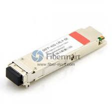
40G QSFP+ BIDI Transceiver
The QSFP+ BIDI handset is created to address the difficulties of fiber foundation by giving the capacity to send full-duplex 40G traffic more than one duplex MMF link with LC connectors(Figure 2). At the end of the day, this handset upholds 40G association more than one sets of MMF links while permitting 40G to be sent utilizing a similar foundation as 10G (10GBASE-SR) without the need to include any strands.
Examination of 40G QSFP+ BIDI and 40G QSFP+ SR4
40GBASE-SR BIDI handset eliminates 40G cabling cost hindrances in server farm organizations. It gives colossal investment funds and effortlessness contrasted with other 40G QSFP+(MMF) transceiver(QSFP+ SR4). Additionally, it permits associations to move the current 10G cabling framework to 40G at no expense and to grow the foundation with low capital speculation.

40G QSFP+ PSM IR4 and 40G QSFP+ PSM LR4 Transceivers
QSFP+ PSM IR4/LR4 is an exceptionally coordinated four-channel optical handset with the benefits of the high thickness of port and lower cost. The optical port embraces a PSM(Parallel Single Mode) innovation and a four-way equal plan MPO/MTP interface which empowers the transmission separation up to 1.4km of IR4 and 10km of LR4. It has been planned with structure factor, optical/electrical association, and computerized analytic interface consistent with MSA(Multi-Source Agreement), these highlights are very attainable to meet the harshest outer working conditions including temperature, moistness, and EMI interface.
The handset can run through the I2C two-wire sequential interface which is accessible to send and get more intricate control signals and to get computerized symptomatic data. By correlation with 40G QSFP+ SR4, they are both similarly of working yet QSFP+ PSM IR4/LR4 is working over SMF(Single Mode Fiber) that is the equal optical signs are conveyed through eight single-mode strands.
40G QSFP+ CWDM LX4/LR4 Lite/LR4/ER4 Transceiver
Recognized from DWDM for example Thick Wavelength Division Multiplex, CWDM known as Coarse Wavelength Division Multiplex is an inventive innovation for moving a lot of information between locales. It builds transfer speed by permitting distinctive information streams to be sent all the while over a solitary optical fiber organization. Thusly, WDM amplifies the use of fiber and assists with streamlining network speculations.
QSFP+ LX4 is an optical module planned particularly for working over both SMF and MMF with transmission separation of up to 150m on OM4 MMF and 2km on SMF. The focal frequencies of the 4 CWDM channels are 1271nm, 1291nm, 1311nm, and 1331nm as individuals from the CWDM frequency framework characterized in ITU-T G.694.2. There is a duplex LC connector for the optical interface and a 148-pin connector for the electrical interface. For applications over SMF, the handset is utilized as a QSFP+ LR4 Lite module and SMF links are legitimately associated with the LC connectors of the module.
QSFP+ LR4 Lite/LR4/ER4 Module bolsters the connection length of up to 2km, 10km, and 30km individually by working over a standard pair of G.652 SMF with duplex LC connector. Inside the gadget, the 40G Ethernet signals are sent more than four frequencies which are figured out how to multiplex and demultiplex. There are 4 information channels to send flags simultaneously. At the sending side, the 4 channels of optical signs are consolidated together by multiplexer while at getting end there is a breakdown handled into 4 channels of optical signals by the demultiplexer. The module includes high thickness, minimal effort, rapid, huge limit, and low force utilization.
CWDM versus PSM, What's The Difference?
From an optical handset module structure perspective, PSM appears to be more financially savvy since it utilizes a solitary uncooled CW (ceaseless wave) laser which parts its yield power into four incorporated silicon modulators. Additionally, its exhibit fiber coupling to an MTP connector is generally less complex. Nonetheless, from a framework perspective, PSM would be more costly when the connection separation is long, basically because of the way that PSM utilizes 8 optical single-mode filaments while CWDM utilizes just 2 optical single-mode strands.
Tantamount with Third-Party QSFP+
All 10Gtek's 40G QSFP+ Transceiver is benevolently viable with outsider QSFP+ gadget, for example, Cisco, Extreme, Brocade, Juniper, HP, Dell, Arista, Huawei, and other known brands. Our 40G QSFP+ handset will give you a phenomenal answer for set up network association without costly expense.
2 notes
·
View notes
Link
C-RAN indicates Cloud Radio Access Netword, which is a centralized cloud computing– an arrangement that architecture concerning radio access networks (RAN) that facilitates the large-scale deployment, collaborative radio technology assistance, including real-time virtualization capabilities. It signifies an evolution of the current wireless communication scheme. It uses the most advanced familiar public radio interface (CPRI) standard, coarse either dense wavelength division multiplexing (CWDM / DWDM) technology and millimeter-wave (MM wave) transmission concerning long-distance signals. The “C” in C-RAN seat alternatively stands for centralized approximately collaborative.
see more : https://bit.ly/31MwRfr
0 notes
Text
WDM Solution
According to the market demand for large transmission capacity in current optical interconnect,network managers are relying more on fiber optics, and requiring more bandwidth and faster transmission rates over ever increasing distances.
What is WDM?
Wavelength Division Multiplexing, WDM, is a technology that increases bandwidth by allowing different data streams at different frequencies to be…
View On WordPress
#Coarse Wave Division Multiplexing (CWDM)#CWDM Mux/Demux#Dense Wave Division Multiplexing (DWDM)#DWDM Mux/Demux#WDM & Optical Network#WDM Solution
0 notes
Text
How to Expand Bandwidth in PON Network with CWDM Technology?
PON (passive optical network) is one of a common optical fiber network architectures. It is characterized by the “splitting” of the optical fiber one or more times, resulting in the sharing of optical fiber among multiple users. However, as networks grow in terms of subscriber counts, the scope and number of services offered, expanding the network bandwidth is inevitable. Coarse Wave Division Multiplexing (CWDM), known for its low cost and scalability to increase fiber capacity as needed, is a preferred method for PON network expansion. This article will focus on using CWDM technology to overcome bandwidth limitations in PON access networks.
CWDM Mux/Demux and OADM (Optical Add-Drop Multiplexer) in Access PON
Fibers in a PON are typically shared with several users. Hence the bandwidth of the fiber originating at the CO (center office) is shared among a group of users. The splitting of the network is accomplished by optical splitters. These splitters can split the fiber 2-32 times, which may introduce high losses in the network. Besides, as different places in a same network need different wavelengths, CWDM Mux is often deployed to multiplex these signals on a single fiber.
In PON (Passive Optical Network) network, whether in ring structures or point-to-point arrangements, different optical nodes need specific wavelengths. Therefore, at each node, a CWDM OADM is used to drop or add certain channels from the fiber as required,. Then the signals will be transmitted to the user through optical fibers. The following picture shows a simple PON network.
How to Expand Bandwidth of PON Network Using CWDM Technology?
Upgrading Access PONs Using Passive CWDM Mux/Demux
In PON networks, OLT has two float directions: upstream (getting an distributing different type of data and voice traffic from users) and downstream (getting data, voice and video traffic from metro network or from a long-haul network and send it to all ONT modules on the ODN).
The following figure represents a situation where existing subscribers intend to upgrade to higher value added bandwidth services. In order to satisfy customers’ needs for IPTV, VoIP, video on demand etc., the 622 Mb/s downstream capacity between the CO and the OLT, providing roughly 20 Mb/s to each subscriber, must increase.
Considering there may be new subscribers and services added, the targeted bandwidth requires at least a downstream CO/OLT link bandwidth of 2.5Gb/s. Therefore, four CWDM wavelengths are introduced to multiply the channels passing between the CO and OLT. This introduction of passive CWDM Mux/Demux can relieve the fiber exhaust effectively. The below figure shows the upgrading process.
Advantages of This Upgrade
Compared with laying a new fiber cable, the upgrade with passive CWDM is easily accomplished within hours after some modest investment in network planning. And the sum of material, labor, equipment and training expense is far less, which explain why many enterprises, private business users of LAN and data storage networks use passive CWDM too.
Expanding EPON Bandwidth Using CWDM Mux/Demux
EPON stands for Ethernet passive optical network. It is an enabling technology that benefits consumers. Here is an EPON network, which was conceived to serve up to 64 subscribers. All users share a single bidirectional optical feed line. With the need for IPTV, HDTV and other higher bandwidth services growing, the downstream capacity 16Mb/s should be improved.
The picture below shows the same EPON deployment upgraded to 4Gb/s bandwidth capacity.
This upgrade uses 4 channels passive CWDM Mux/Demux to extend the whole network capacity, allowing the downstream capacity increase four times without affecting the upstream traffic.
Advantage of This Expansion
Using CWDM Mux/Demux effectively increases the network bandwidth capacity and reduces the cost. At the same time, it requires minimal modification of the existing infrastructure, which also saves labors.
Summary
CWDM technology offers significant benefits of low investment, minimal operating cost and very simple and straightforward upgrade planning and implementation. In addition, passive CWDM also provides scalability and network flexibility for network growth and bandwidth demands in the future. FS.COM supplies different channels of CWDM components. Welcome to contact us via [email protected].
Related article: Examples of CWDM Network Deployment Solution
Sources:http://www.fiber-optic-components.com/how-to-expand-bandwidth-in-pon-network-with-cwdm-technology.html
0 notes
Text
How to Use WDM for Fiber Capacity Expansion?
Imagine turning a cottage into a majestic skyscraper without having to deliver any innovation or construction. This is what wavelength division multiplexing (WDM) allows with your existing fiber optic network. The hunger for bandwidth propels service providers to make a substantial investment in upgrading fiber cabling infrastructure. This can be a challenge both economically and practically. However, the WDM technology offers an alternative to increase capacity on the fiber links that are already in place. Without deploying additional optical fiber, WDM greatly reduces the cost of network expansion.
WDM Technology Explanation
Let’s begin with the most fundamental question: What is WDM technology? Short for wavelength division multiplexing, WDM is a way of transmitting multiple simultaneous data streams over the same fiber. Since this happens simultaneously, WDM does not impact transmission speed, latency or bandwidth. WDM functions as multiplexing multiple optical signals on a single fiber by using different wavelengths, or colors, of laser light to carry different signals. Network managers can thus realize a multiplication effect in their available fiber’s capacity with WDM.

To implement WDM to the infrastructure is rather simple, WDM setup generally consists of the following:
WDM transmit devices, each operating at a different wavelength
Multiplexer, a passive device that combines the different light sources into a blended one
Fiber infrastructure
De- Multiplexer, a passive device that splits the blended light source into separate ones
WDM receive devices

What Capacity Increase Can We Expect?
There are two variants of WDM: CWDM (coarse wave-division multiplexing) and DWDM (dense wave-division multiplexing). The only difference between them is the band in which they operate, and the spacing of the wavelengths and thus the number of wavelength or channels that can be used.
When using WDM on existing fiber cabling, you should also consider the fiber type (single-mode or multimode) and loss level. For CWDM, 8 to 18 devices may be possible, whereas for DWDM, up to 40 channels are the most common case, but it is possible to reach up to 160 channels.

Choose the Right Type of WDM
We’ve known that both CWDM and DWDM are available to optimize network capacity. Then, here comes another question: should I choose CWDM or DWDM technology? Let’s make a comparison of them.
Coarse Wave Division Multiplexing (CWDM)
CWDM increases fiber capacity in either 4, 8, or 18 channel increments. By increasing the channel spacing between wavelengths on the fiber, CWDM allows for a simple and affordable method of carrying up to 18 channels on a single fiber. CWDM channels each consume 20 nm of space and together use up most of the single-mode operating range.

Benefits of CWDM:
Passive equipment that uses no electrical power
No configuration is necessary, much lower cost per channel than DWDM
Scalability to grow the fiber capacity as needed
With little or no increased cost
Protocol transparent and ease of use
Drawbacks of CWDM:
18 channels may not be enough, and fiber amplifier cannot be used with them
Passive equipment that has no management capabilities
Not the ideal choice for long-haul networks
Dense Wave Division Multiplexing (DWDM)
DWDM allows many more wavelengths to be combined onto one fiber. DWDM comes in two different versions: an active solution and a passive solution. An active solution requires wavelength management and is well-suited for applications involving more than 32 links over the same fiber. In most cases, passive DWDM is regarded as a more realistic alternative to active DWDM.

Benefits of DWDM:
Ideal for use in long-haul and areas of greater customer density
Up to 32 channels can be done passively
Up to 160 channels with an active solution
Active solutions involve EDFA optical amplifiers to achieve longer distances

Drawbacks of DWDM:
DWDM solutions are quite expensive
Active DWDM solutions require a lot of set-up and maintenance expense
Very little scalability for deployments under 32 channels, much unnecessary cost is incurred per channel
To sum it up, CWDM can be typically used for applications that do not require the signal to travel great distances and in locations where not many channels are required. While for applications that demand for a high number of channels or for long-haul applications, DWDM is the ideal solution.
Considerations for Deploying WDM
Making sure that the CWDM and DWDM will perform properly is critical, so one should account for the following aspects for when deploying.
1.Before buying a mux or demux for use in an unconditioned cabinet or splice case, verify that the operating temperature will fit the application. And ensure that the CWDM or DWDM will be able to operate within the temperatures in which they will be placed.
2.Take the insertion loss of WDM network into account. Using the maximum insertion loss value in the link budget is a good idea. Calculate the loss for both the mux and demux components.
Conclusion
WDM technology provides an ideal solution for fiber exhaust problem that many communication providers are experiencing. It eliminates the need for investing on new fiber construction projects while greatly increases fiber capacity of the existing infrastructure. Hope what presented in the article could help you to choose the right WDM solution.
Source: http://www.fiber-optic-solutions.com/use-wdm-fiber-capacity-expansion.html
0 notes
Text
Wave Division Multiplexing: Why it’s Good for Fiber
Wave Division Multiplexing: Why it’s Good for Fiber
by http://www.fiber-mart.com
A single optical fiber can carry a huge amount of bandwidth using Time-Division Multiplexing (TDM) and Coarse Wavelength Division Multiplexing (CWDM), which may be combined. TDM was developed for digital telephony to send independent signals over a single fiber using synchronized switches at each end so that each signal appears on the line in short bursts, creating an…
View On WordPress
0 notes