#Connecting a Relay to Arduino
Explore tagged Tumblr posts
Visit Tumblr Blog
Explore Tumblr blogs with no restrictions, modern design and the best experience.
Last Seen Tumblr Blogs


Fun Fact
1,644 Tumblr posts in 1 second.
Text
Top 10 Projects for BE Electrical Engineering Students
Embarking on a Bachelor of Engineering (BE) in Electrical Engineering opens up a world of innovation and creativity. One of the best ways to apply theoretical knowledge is through practical projects that not only enhance your skills but also boost your resume. Here are the top 10 projects for BE Electrical Engineering students, designed to challenge you and showcase your talents.
1. Smart Home Automation System
Overview: Develop a system that allows users to control home appliances remotely using a smartphone app or voice commands.
Key Components:
Microcontroller (Arduino or Raspberry Pi)
Wi-Fi or Bluetooth module
Sensors (temperature, motion, light)
Learning Outcome: Understand IoT concepts and the integration of hardware and software.
2. Solar Power Generation System
Overview: Create a solar panel system that converts sunlight into electricity, suitable for powering small devices or homes.
Key Components:
Solar panels
Charge controller
Inverter
Battery storage
Learning Outcome: Gain insights into renewable energy sources and energy conversion.
3. Automated Irrigation System
Overview: Design a system that automates the watering of plants based on soil moisture levels.
Key Components:
Soil moisture sensor
Water pump
Microcontroller
Relay module
Learning Outcome: Learn about sensor integration and automation in agriculture.
4. Electric Vehicle Charging Station
Overview: Build a prototype for an electric vehicle (EV) charging station that monitors and controls charging processes.
Key Components:
Power electronics (rectifier, inverter)
Microcontroller
LCD display
Safety features (fuses, circuit breakers)
Learning Outcome: Explore the fundamentals of electric vehicles and charging technologies.
5. Gesture-Controlled Robot
Overview: Develop a robot that can be controlled using hand gestures via sensors or cameras.
Key Components:
Microcontroller (Arduino)
Motors and wheels
Ultrasonic or infrared sensors
Gesture recognition module
Learning Outcome: Understand robotics, programming, and sensor technologies.
6. Power Factor Correction System
Overview: Create a system that improves the power factor in electrical circuits to enhance efficiency.
Key Components:
Capacitors
Microcontroller
Current and voltage sensors
Relay for switching
Learning Outcome: Learn about power quality and its importance in electrical systems.
7. Wireless Power Transmission
Overview: Experiment with transmitting power wirelessly over short distances.
Key Components:
Resonant inductive coupling setup
Power source
Load (LED, small motor)
Learning Outcome: Explore concepts of electromagnetic fields and energy transfer.
8. Voice-Controlled Home Assistant
Overview: Build a home assistant that can respond to voice commands to control devices or provide information.
Key Components:
Microcontroller (Raspberry Pi preferred)
Voice recognition module
Wi-Fi module
Connected devices (lights, speakers)
Learning Outcome: Gain experience in natural language processing and AI integration.
9. Traffic Light Control System Using Microcontroller
Overview: Design a smart traffic light system that optimizes traffic flow based on real-time data.
Key Components:
Microcontroller (Arduino)
LED lights
Sensors (for vehicle detection)
Timer module
Learning Outcome: Understand traffic management systems and embedded programming.
10. Data Acquisition System
Overview: Develop a system that collects and analyzes data from various sensors (temperature, humidity, etc.).
Key Components:
Microcontroller (Arduino or Raspberry Pi)
Multiple sensors
Data logging software
Display (LCD or web interface)
Learning Outcome: Learn about data collection, processing, and analysis.
Conclusion
Engaging in these projects not only enhances your practical skills but also reinforces your theoretical knowledge. Whether you aim to develop sustainable technologies, innovate in robotics, or contribute to smart cities, these projects can serve as stepping stones in your journey as an electrical engineer. Choose a project that aligns with your interests, and don’t hesitate to seek guidance from your professors and peers. Happy engineering!
5 notes
·
View notes
Text
A two-channel relay module featuring 2x Omron G3MB-202P solid state relays. This 5V 2-Channel SSR Solid State Relay Module 240V 2A Output with Resistive Fuse is capable of switching AC voltages between 100 and 240V at up to a 2A current. The module can be controlled from a 5V digital source such as an Arduino microcontroller.
This is a 2 Channel SSR relay module, each relay channel has 3 separate terminals, NO (Normal Open), COM (Common), NC (Normal Closed). When the input logic voltage is applied to the coil, the NC will disconnect from the COM breaking the conductivity between the two. At the same time, the NO will connect with the COM allowing conductivity between them. Depending on your wiring this will turn on or off the connected load.
3 notes
·
View notes
Text
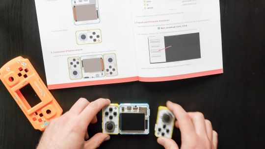
Terry and Julia Group Project 1
Video Walkthrough LinkImage of the Project
The last two weeks Terry and I worked on our project called “Hit the Dick” (see video walkthrough above).
Aim of the Game:Each player has one strap-on game controller containing an Airpump, a rgb-LED, as well as a capacitive touch sensor attached to the tip. The game starts by randomly choosing one player whose strap-on will light up green after a random delay. That player has to hit the other players strap on within 3 seconds. If the player succeeds in hitting it before the opponent has dodged, the players starp-on will fill with a little bit of air. Players then take turn until one of the players has gained 5 points.
Hardware:LED: serves to indicate the current state of the game: Who is hitting, who has to dodge. AirPump that fills Silicone strap-on with air: Serves as a funny way to indicate the players points. The higher the Point count, the “higher” the strap-on will be (lol).Capacitive Touch Sensor: detects the slapping
Process:Terry and I ran into a few difficulties during building this project: Here are some interesting findings summed up:
Building the silicone strap-ons: It was really challenging to create 3D printed negatives that would serve as the mold for the strap-ons because we needed to make sure we had enough hallow space for the air to fill.
Getting the Airpumps to work: After some testing, we realized that the Arduino does not have enough power to power the Airpumps using the GPIO pins. Hence, we ended up using a Relay connected to an external 5V 2A power source!
3 notes
·
View notes
Text
Wemos D1 Mini Pinout: Master the ESP8266 Mini Pinout for Your Next IoT Project
If you're exploring IoT projects, the Wemos D1 Mini is a tiny but powerful board you’ll want in your toolkit. Built around the reliable ESP8266 chip, it combines Wi-Fi connectivity with a compact, breadboard-friendly design. This makes it perfect for projects like smart home automation, DIY gadgets, or even experimenting with sensors and actuators.
One of the key things you need to know is the Wemos D1 Mini pinout, as it lays the foundation for what your board can do. With 11 GPIO pins, power options (3.3V and 5V), and essential pins like TX, RX, and A0, the Wemos D1 Mini offers plenty of flexibility for small-scale IoT projects. The ESP8266 Mini pinout adds another layer of versatility, making it easy to work with various modules and devices while maintaining compatibility with standard Arduino IDE libraries.
Key pin highlights:
GPIO Pins: Ideal for connecting sensors, LEDs, relays, and more.
A0 Pin: Used for analog inputs, with a range of 0-3.3V.
TX/RX Pins: Essential for serial communication with other devices.
Power Pins: Supports both 5V and 3.3V power supplies for flexibility.
Whether you’re working on a Wi-Fi-enabled weather station, a smart light controller, or a quirky robot, understanding the Wemos D1 Mini pinout and ESP8266 Mini pinout is key to maximizing your board's potential.
Ready to dive deeper? Check out our detailed guide on pinouts here and get started with your next IoT adventure today!
#WemosD1Mini#WemosD1MiniPinout#D1MiniPinout#ESP8266Pinout#WemosPinoutGuide#Microcontroller#IoTDevelopment#ArduinoProjects#ESP8266Projects#WemosProjects#WemosD1MiniGuide#IoTDevices#EmbeddedSystems#WemosTutorial#PinoutDiagram
0 notes
Video
youtube
Smart Shopping Cart with Automatic Billing System through RFID and GSM | Smart Shopping Cart with Automatic Billing System | Smart shopping trolley with gsm sms alert arduino | Smart shopping trolley project report | Smart shopping cart with Automatic billing system project | Smart shopping trolley with automated billing using Arduino | Smart trolley using RFID project report | Smart shopping trolley with automated billing using Arduino ppt | Smart shopping cart project.***********************************************************If You Want To Purchase the Full Working Project KITMail Us: [email protected] Name Along With You-Tube Video LinkWe are Located at Telangana, Hyderabad, Boduppal. Project Changes also Made according to Student Requirementshttp://svsembedded.com/ https://www.svskits.in/ http://svsembedded.in/ http://www.svskit.com/M1: 91 9491535690 M2: 91 7842358459 We Will Send Working Model Project KIT through DTDC / DHL / Blue Dart We Will Provide Project Soft Data through Google Drive1. Project Abstract / Synopsis 2. Project Related Datasheets of Each Component3. Project Sample Report / Documentation4. Project Kit Circuit / Schematic Diagram 5. Project Kit Working Software Code6. Project Related Software Compilers7. Project Related Sample PPT’s8. Project Kit Photos9. Project Kit Working Video linksLatest Projects with Year Wise YouTube video Links152 Projects https://svsembedded.com/ieee_2024.php133 Projects https://svsembedded.com/ieee_2023.php157 Projects https://svsembedded.com/ieee_2022.php135 Projects https://svsembedded.com/ieee_2021.php 151 Projects https://svsembedded.com/ieee_2020.php103 Projects https://svsembedded.com/ieee_2019.php61 Projects https://svsembedded.com/ieee_2018.php171 Projects https://svsembedded.com/ieee_2017.php170 Projects https://svsembedded.com/ieee_2016.php67 Projects https://svsembedded.com/ieee_2015.php55 Projects https://svsembedded.com/ieee_2014.php43 Projects https://svsembedded.com/ieee_2013.php1500 Projects https://www.svskit.com/2025/01/1500-f...***********************************************************Creating an Arduino-based smart shopping trolley with features like adding/deleting items and auto billing with GSM SMS alert involves several components and steps. Here's a high-level overview of how you can build such a system:Components Needed:1. Arduino board (e.g., Arduino Uno or Arduino Mega)2. GSM module (e.g., SIM900)3. RFID reader4. RFID tags or NFC cards5. LCD display6. Keypad7. Load cells or weight sensors8. Servo motor (for automatic door opening, if desired)9. Relays and transistors (for controlling the door and billing system)10. Power supply11. Breadboard and jumper wires12. Shopping cart with a sturdy frameSteps to Build the System:1. Setup Arduino and GSM Module:• Connect the GSM module to the Arduino.• Install necessary libraries for the GSM module.• Configure the GSM module to send and receive SMS alerts.2. Interface RFID Reader:• Connect the RFID reader to the Arduino.• Write code to read RFID/NFC tags and associate them with product data.3. Interface LCD Display and Keypad:• Connect the LCD display and keypad to the Arduino.• Use the keypad to input item codes or quantities.• Display item details and prices on the LCD.4. Implement Add/Delete Functionality:• Create functions to add and delete items from the shopping cart.• Maintain a list of selected items with their quantities.5. Auto Billing System:• Calculate the total bill based on the selected items and their prices.• Display the total on the LCD.• Implement a billing mechanism that accepts payment (e.g., cash or card).6. Weight Sensing (Optional):• If you want to automate item addition based on weight, use load cells or weight sensors.• Add items to the cart when they are placed on the trolley, and remove them when taken out.7. Automatic Door Control (Optional):• Use a servo motor to control the trolley's door.• Automatically open the door when an item is added or when the billing process is complete.8. GSM SMS Alerts:• Send SMS alerts using the GSM module to a predefined number.• Send alerts for items added, deleted, or when the billing is completed.9. User Interface and Interaction:• Implement a user-friendly interface on the LCD for item selection, deletion, and payment.• Provide feedback and prompts to guide the user through the process.10. Testing and Debugging:• Test the entire system thoroughly to ensure all components work as expected.• Debug any issues with RFID reading, item tracking, billing, or GSM communication.11. Power Supply and Integration:• Ensure a reliable power supply for the Arduino and all components.• Integrate the system into the shopping cart securely
1 note
·
View note
Text
Arduino Projects
Both a physical programmable circuit board (microcontroller) and software (Arduino IDE) are components of Arduino, which is used to develop and upload code to the board. From basic LED blinkers to complicated home automation systems, the platform can handle a broad variety of tasks. It is a well-liked option for makers all around the world because of its user-friendly interface, robust community support, and cost.
Why Choose Arduino for Your Projects?
Easy to Use: Arduino is suitable for both novices and experts because of its straightforward hardware connections and user-friendly IDE.
Accessible and Inexpensive: Arduino boards and parts are readily accessible and reasonably priced.
Huge Community Support: The learning curve is accelerated by having access to forums, tutorials, and an extensive collection of shared projects.
Compatibility: To increase project functionality, Arduino supports a large variety of sensors, actuators, and shields.
Exciting Arduino Project Ideas
Beginner Projects
Intermediate Projects
Advanced Projects
Components Required for Arduino Projects
Arduino Boards: Nano, Mega, or Uno models.
Sensors include those for motion, light, gas, temperature, and soil moisture.
Actuators include relays, motors, and servos.
LCD, OLED, or LED screens are examples of displays.
Bluetooth, Wi-Fi, or GSM modules are examples of connectivity modules.
Other: resistors, capacitors, jumper wires, and breadboards.
Arduino and STEM Education
In STEM (science, technology, engineering, and mathematics) education, Arduino is a vital instrument. It gives students practical learning opportunities while teaching them electronics, coding, and problem-solving techniques. Arduino projects are incorporated into the curricula of many colleges and institutions in order to promote technical proficiency and creativity.
For both professionals and enthusiasts, Arduino projects offer a plethora of opportunities. You can build critical technical abilities and realize your creative ideas by investigating different applications. Arduino's extensive community and limitless resources make it possible for anybody to explore the exciting fields of programming and electronics.
So take out your Arduino board, let your imagination run wild, and get to work creating something incredible right now!
To know more, click here.
0 notes
Text
5V Single Channel Relay Module: A Detailed Guide
The 5V Single Channel Relay Module is a powerful and compact device that serves as a bridge between low-power circuits and high-power devices. It is commonly used in projects requiring electrical isolation or automation, making it popular among hobbyists and engineers alike. In this guide, we will explore its functions, applications, wiring, and much more to give you a full understanding of this versatile module.
What is a 5V Single Channel Relay Module?
A 5V Single Channel Relay Module is an electronic switching device designed to control high-voltage electrical devices using a low-power input. The term "5V" refers to the operating voltage required to activate the relay, while "single channel" means it can control one device or circuit at a time.
The module is widely used in home automation, robotics, and various DIY projects. Its ability to switch between circuits without a direct electrical connection makes it a safer choice for controlling high-voltage appliances.
How Does a 5V Single Channel Relay Module Work?
The relay module operates as an electromechanical switch. It uses a small input voltage to energize an internal coil, creating a magnetic field. This magnetic field moves a lever inside the relay to either open or close a circuit. By doing so, it allows or interrupts the flow of current to the connected device.
The module typically has three main connections:
Input Pins: For connecting the control signal.
Common Pin (COM): The shared connection between the relay and the device.
Normally Open (NO) and Normally Closed (NC): These determine the state of the circuit (open or closed) when the relay is activated or deactivated.
Features of a 5V Single Channel Relay Module
Low Power Requirement: Operates on just 5V input.
Isolation: Electrical isolation ensures safety between low-voltage control circuits and high-voltage devices.
LED Indicators: Built-in LEDs indicate the relay’s state, making it easy to troubleshoot.
Compact Design: Small and lightweight, suitable for various projects.
Applications of the 5V Single Channel Relay Module
The 5V Single Channel Relay Module has countless uses in modern electronics, such as:
Home Automation: Control appliances like lights, fans, or water pumps using microcontrollers or development boards like Arduino or Raspberry Pi.
Robotics: Enable remote or automated control of motors and actuators.
Industrial Automation: Automate machinery and monitor processes.
Smart IoT Systems: Integrate with IoT platforms to create smart, connected systems.
How to Wire a 5V Single Channel Relay Module
Connecting a 5V Single Channel Relay Module to a microcontroller is straightforward. Follow these steps for basic wiring:
Power the Module: Connect the VCC pin to the 5V output of your microcontroller or external power supply.
Connect the Ground: Link the GND pin of the relay to the ground pin of your controller.
Signal Pin: Attach the IN pin to the microcontroller's GPIO pin that will control the relay.
Device Connection: Wire the high-voltage device to the NO, NC, and COM pins based on your requirements.
Always ensure proper insulation and avoid direct contact with live wires during setup.
Benefits of Using a 5V Single Channel Relay Module
Safety: Provides electrical isolation, protecting the low-power circuit.
Versatility: Works with a range of devices and voltages.
Reliability: Durable and can withstand frequent switching operations.
How to Test a 5V Single Channel Relay Module
To test the module, follow these simple steps:
Power Up the Relay: Connect the module to a 5V power source.
Apply Control Signal: Send a HIGH or LOW signal to the input pin.
Listen for a Click: A clicking sound indicates the relay is switching states.
Check the LED Indicator: Ensure the LED lights up when activated.
Testing ensures the module functions as intended before integrating it into your project.
Choosing the Right Relay Module
When selecting a relay module, consider the following factors:
Operating Voltage: Ensure compatibility with your controller.
Load Capacity: Check the maximum current and voltage the relay can handle.
Channels: Choose a module with an appropriate number of channels based on your needs.
Integrating the 5V Single Channel Relay Module with Arduino
One of the most popular applications of this module is in Arduino projects. Here’s a simple example:
Components Required
Arduino Board
5V Single Channel Relay Module
Jumper Wires
Load (e.g., a light bulb)
Steps
Connect the relay module's VCC and GND to the Arduino’s 5V and GND pins.
Attach the IN pin to a digital GPIO pin (e.g., pin 7).
Write a program to toggle the relay using Arduino’s digitalWrite function.
Upload the code and observe the relay switching the connected load.
Maintenance and Troubleshooting
Regular maintenance can extend the lifespan of your 5V Single Channel Relay Module. Check for the following:
Loose Connections: Ensure all wires are securely connected.
Dust and Debris: Clean the module periodically to prevent short circuits.
Wear and Tear: Inspect for physical damage or corrosion.
If the module fails to function, verify the power supply and input signals. Replace damaged modules promptly to avoid system downtime.
0 notes
Text
DIY Smart Garden with Automated Irrigation System
Introduction
Welcome to our DIY project guide on creating a Smart Garden with an Automated Irrigation System! This innovative project uses technology to optimize water usage, ensuring your plants receive the right amount of hydration while minimizing waste. Perfect for home gardens, greenhouses, or small farms, this automated system uses soil moisture sensors and weather data to control water valves efficiently.

Why Build a Smart Garden?
Traditional gardening methods often lead to over-watering or under-watering plants, which wastes water and can harm your garden. By integrating smart technology into your gardening routine, you can monitor and control your garden’s irrigation system remotely, allowing for efficient water management.
Benefits of a Smart Garden
Water Conservation: Reduces water waste by watering only when necessary.
Healthier Plants: Ensures optimal moisture levels for plant growth.
Remote Monitoring: Check and control your garden from anywhere.
Data Insights: Analyze watering patterns and make informed decisions.
Key Components and Technologies
To build your Smart Garden, you will need the following components:
Microcontroller: Choose either a Raspberry Pi or Arduino as the central processing unit for your system.
Soil Moisture Sensors: These sensors measure the moisture level in the soil.
Temperature and Humidity Sensors: Monitor the environmental conditions that affect plant watering needs.
Water Pump or Solenoid Valves: Control the water flow to your plants based on sensor data.
Wi-Fi Module: Enables remote monitoring and control through a web application or mobile app.
Cloud Service: Use Cloudtopiaa to store and analyze data over time. This cloud platform allows you to log sensor data, analyze trends, and remotely monitor your garden’s status.
Additional Tools:
Jumper wires and a breadboard
A power supply for the microcontroller
Tubing for water delivery (if using a pump)
Step-by-Step Guide
Step 1: Set Up the Microcontroller
Choose Your Microcontroller: For this guide, we’ll use a Raspberry Pi for its ease of use and capabilities. Install the latest version of Raspbian OS.
Connect the Components:
Connect the soil moisture sensors to the GPIO pins on the Raspberry Pi.
Connect the temperature and humidity sensors (DHT11 or similar).
If using a water pump, connect it to a relay module that can be controlled by the Raspberry Pi.
Step 2: Install Required Libraries
Open the terminal on your Raspberry Pi and install necessary libraries for sensor data collection and Wi-Fi connectivity:sudo apt-get update sudo apt-get install python3-pip pip3 install Adafruit_DHT
Step 3: Program the Sensors
Create a Python script to read data from the sensors. Here’s a basic example:import Adafruit_DHT import time import RPi.GPIO as GPIO
# Set GPIO mode GPIO.setmode(GPIO.BCM)
# Sensor setup DHT_SENSOR = Adafruit_DHT.DHT11 DHT_PIN = 4 # GPIO pin for DHT sensor MOISTURE_PIN = 17 # GPIO pin for soil moisture sensor
def read_sensors(): # Read temperature and humidity humidity, temperature = Adafruit_DHT.read_retry(DHT_SENSOR, DHT_PIN) # Read soil moisture level moisture_level = GPIO.input(MOISTURE_PIN) return temperature, humidity, moisture_level
while True: temp, humidity, moisture = read_sensors() print(f'Temperature: {temp}°C, Humidity: {humidity}%, Soil Moisture: {moisture}') time.sleep(10)
Step 4: Control the Water Pump
Expand the script to control the water pump based on the moisture level:WATER_PUMP_PIN = 27 # GPIO pin for the water pump relay GPIO.setup(WATER_PUMP_PIN, GPIO.OUT)
def water_plants(moisture): if moisture < 300: # Adjust threshold based on your sensor calibration GPIO.output(WATER_PUMP_PIN, GPIO.HIGH) # Turn on water pump print("Watering the plants...") time.sleep(10) # Watering duration GPIO.output(WATER_PUMP_PIN, GPIO.LOW) # Turn off water pump
while True: temp, humidity, moisture = read_sensors() water_plants(moisture) time.sleep(600) # Check every 10 minutes
Step 5: Remote Monitoring and Cloud Integration with Cloudtopiaa
To monitor your garden remotely, integrate it with Cloudtopiaa for real-time data logging, trend analysis, and remote control of your irrigation system. Here’s how:
Sign Up and Set Up Cloudtopiaa:
Create an account on Cloudtopiaa and set up a cloud project for your garden.
Obtain your API key and configure the project to receive data from your Raspberry Pi.
Install Cloudtopiaa SDK:
Install the Cloudtopiaa SDK for data transmission. In your Raspberry Pi terminal, install the SDK:pip3 install cloudtopiaa-sdk
Update Your Python Script to Log Data to Cloudtopiaa:
Use the Cloudtopiaa SDK to log sensor data, set alerts, and monitor trends.
from cloudtopiaa_sdk import Cloudtopiaa
cloudtopiaa = Cloudtopiaa(api_key='Your_Cloudtopiaa_API_Key')
while True: temp, humidity, moisture = read_sensors() # Log data to Cloudtopiaa cloudtopiaa.log_data({ "temperature": temp, "humidity": humidity, "moisture": moisture }) water_plants(moisture) time.sleep(600) # Check every 10 minutes
This integration enables you to monitor your garden’s conditions from anywhere, set up notifications when moisture levels are low, and analyze long-term data to optimize water usage.
Conclusion
Congratulations! You’ve successfully built a Smart Garden with an Automated Irrigation System using Cloudtopiaa. With this setup, you can efficiently manage your garden’s water needs, conserve resources, and monitor conditions from anywhere. As you refine your project, consider exploring additional features like integrating weather APIs for advanced irrigation control or adding more sensors to enhance functionality.
Additional Resources
Raspberry Pi Documentation
Arduino Project Hub
Cloudtopiaa Documentation
By applying these skills in IoT sensor integration, automation, and cloud data logging, you’re well on your way to mastering smart gardening techniques!
#cloudtopiaa #ITServices #SmartGarden #AutomatedIrrigation #DIYGarden #IrrigationTech #GrowWithTech
0 notes
Text
Controlling Multiple Relays with Arduino: A Comprehensive Guide
Introduction
Relay modules are essential components in the world of electronics, allowing you to control high-power devices with low-voltage signals. When combined with the versatility of Arduino, you can create a wide range of automated systems. In this blog post, we'll explore how to control multiple relay modules using an Arduino board.
Understanding Relay Modules
A relay module typically consists of one or more relays, each with a control pin and a pair of output terminals. By applying a low voltage (usually 5V) to the control pin, you can switch the relay, connecting or disconnecting the output terminals. This allows you to control devices that require higher voltages and currents than the Arduino can directly provide.
Required Components
Arduino board (e.g., Uno, Nano)
Relay module (2-channel or more)
Jumper wires
Breadboard (optional)
Power supply (5V DC)
Circuit Diagram
Power Supply: Connect the 5V and GND pins of the relay module to the 5V and GND pins of the Arduino, respectively.
Relay Control: Connect the control pins of the relays to digital pins on the Arduino (e.g., pins 2, 3, 4, and 5).
Arduino Code
const int relayPins[] = {2, 3, 4, 5}; // Array to store relay pin numbers
void setup() {
for (int i = 0; i < 4; i++) {
pinMode(relayPins[i], OUTPUT);
}
}
void loop() {
// Control the relays as needed
digitalWrite(relayPins[0], HIGH); // Turn relay 1 ON
digitalWrite(relayPins[1], LOW); // Turn relay 2 OFF
// ... and so on
}
Explanation
Pin Definition: An array relayPins is used to store the pin numbers connected to the relay control pins.
Setup:
pinMode(relayPins[i], OUTPUT): This line sets each pin in the array as an output pin.
Loop:
digitalWrite(relayPins[i], HIGH/LOW): This line controls the state of a specific relay by setting the corresponding pin to HIGH (ON) or LOW (OFF).
Expanding the Functionality
Sensor-Based Control: Use sensors (e.g., temperature, light, motion) to trigger relay actions based on specific conditions.
Timer-Based Control: Employ the millis() function to implement time-based switching.
Remote Control: Combine with wireless modules (e.g., Bluetooth, Wi-Fi) to control the relays remotely.
Multiple Relay Modules: Connect multiple relay modules to the Arduino to control more devices.
Safety Considerations
Voltage and Current Ratings: Ensure that the relay module's voltage and current ratings are suitable for the load you're controlling.
Heat Dissipation: If controlling high-power loads, consider using heat sinks or other cooling measures.
Proper Wiring: Double-check all connections to avoid short circuits and potential damage.
By mastering the art of controlling multiple relay modules with Arduino, you can create a wide range of innovative projects, from home automation systems to industrial control applications.
Would you like to delve deeper into a specific application or have any other questions about relay module control with Arduino?
0 notes
Text


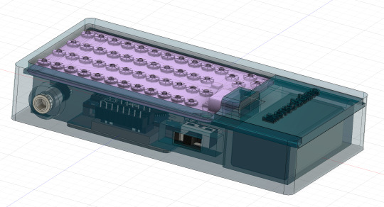
Morseduino keyboard based CW keyer
Based on an Arduino nano and CardKB mini keyboard. The parts you need to build it are
Arduino nano
CardKB mini keyboard
BC547 NPN transistor
1K resistor
5v reed relay
Socket for the reed relay
Stereo jack for the output
Two on-off-on switches, for speed and power
3D printer to make the enclosure
link to enclosure below

Wire up the speed switch with the centre pin to D13 of the Arduino, this is the reference pin. Connect the either side of the speed switch to D2 and D3 respectively
Wiring up the relay
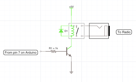
The diode is not needed with a reed relay IC

The Arduino code
You will need this for the hardware to work, copy and paste it into Arduino IDE. Please respect my work and leave the top comment in.
/*
(c) 12/10/2024 Morseduino by Robert Rayner, M0YNW
This software has no warranty and you use it at your own risk.
*/
#include <Wire.h>
// Define pins for relay and LED
const int relayPin = 7; // relay output
const int ledPin = LED_BUILTIN; // built in LED (specify pin number if using an external LED)
const int speedSwitchA = 2; // Pin connected to one side of the switch
const int speedSwitchB = 3; // Pin connected to the other side of the switch
const int fastWPM = 20; // Fast speed (20 WPM)
const int slowWPM = 12; // Slow speed (12 WPM)
int wpm = fastWPM; // Default WPM is set to fast
// Morse code timing variables
int dotDuration, dashDuration, elementSpace, letterSpace, wordSpace;
// Morse code representation for characters (A-Z, 0-9, /, =, . ?)
const char* morseCodeMap[43] = {
".-", "-...", "-.-.", "-..", ".", "..-.", "--.", "....", "..", ".---", // A-J
"-.-", ".-..", "--", "-.", "---", ".--.", "--.-", ".-.", "...", "-", // K-T
"..-", "...-", ".--", "-..-", "-.--", "--..", // U-Z
"-----", ".----", "..---", "...--", "....-", ".....", "-....", // 0-5
"--...", "---..", "----.", // 6-9
"-..-.", "..--..", "-...-", ".-.-.-" //Special characters: / . ? =
};
// CardKB I2C address
#define CARDKB_ADDR 0x5F
// Function to map character to Morse code
const char* getMorseCode(char c) {
if (c >= 'A' && c <= 'Z') {
return morseCodeMap[c - 'A'];
} else if (c >= '0' && c <= '9') {
return morseCodeMap[26 + (c - '0')];
} else if (c == '/') {
return morseCodeMap[36]; // Morse for /
} else if (c == '?') {
return morseCodeMap[37]; // Morse for ,
} else if (c == '=') {
return morseCodeMap[38]; // Morse for =
} else if (c == '.') {
return morseCodeMap[39]; // Morse for .
} else {
return ""; // Return empty for unsupported characters
}
}
// Function to read the slide switch and set WPM
void readSpeedSwitch() {
// Read both switch states with internal pull-up resistors enabled
int switchAState = digitalRead(speedSwitchA);
int switchBState = digitalRead(speedSwitchB);
// Update WPM if one switch is high and the other is low
if (switchAState == LOW && switchBState == HIGH) {
wpm = fastWPM; // Set WPM to fast speed (20 WPM)
} else if (switchAState == HIGH && switchBState == LOW) {
wpm = slowWPM; // Set WPM to slow speed (12 WPM)
}
// Update timing variables based on the current WPM
updateWpmTiming();
}
// Function to transmit Morse code
void transmitMorse(const char* morse) {
while (*morse) {
if (*morse == '.') {
digitalWrite(relayPin, HIGH);
digitalWrite(ledPin, HIGH); // Turn on LED
delay(dotDuration);
digitalWrite(relayPin, LOW);
digitalWrite(ledPin, LOW); // Turn off LED
delay(elementSpace);
} else if (*morse == '-') {
digitalWrite(relayPin, HIGH);
digitalWrite(ledPin, HIGH); // Turn on LED
delay(dashDuration);
digitalWrite(relayPin, LOW);
digitalWrite(ledPin, LOW); // Turn off LED
delay(elementSpace);
}
morse++;
}
delay(letterSpace); // Space between letters
}
// Function to read a key from CardKB
char readCardKB() {
char key = '\0'; // Initialize with null character
Wire.requestFrom(CARDKB_ADDR, 1); // Request one byte from the CardKB
if (Wire.available()) {
key = Wire.read(); // Read the byte from the CardKB
}
return key; // Return the key (or null if nothing was read)
}
// Update WPM and timing variables based on new WPM
void updateWpmTiming() {
dotDuration = 1200 / wpm;
dashDuration = dotDuration * 3;
elementSpace = dotDuration;
letterSpace = dotDuration * 3;
wordSpace = dotDuration * 7;
}
void setup() {
Serial.begin(9600);
pinMode(relayPin, OUTPUT);
pinMode(ledPin, OUTPUT); // Set the LED pin as OUTPUT
Wire.begin(); // Initialize I2C communication with the CardKB
// Enable internal pull-up resistors for the switch pins
pinMode(speedSwitchA, INPUT_PULLUP);
pinMode(speedSwitchB, INPUT_PULLUP);
digitalWrite(13, HIGH); //connect this to the centre pin of the speed switch
updateWpmTiming(); // Set initial WPM and timing values
}
void loop() {
// Read the current position of the slide switch
readSpeedSwitch();
// Read key from CardKB
char c = readCardKB();
if (c != '\0') { // If a key was pressed
Serial.print("Key pressed: ");
Serial.println(c);
const char* morse = getMorseCode(toupper(c)); // Convert to uppercase and get Morse code
if (morse[0] != '\0') { // If valid Morse code
transmitMorse(morse);
} else if (c == ' ') { // Handle space between words
delay(wordSpace);
}
}
}
0 notes
Text

Lm393 LDR Sensor Module
The LM393 LDR Sensor Module utilizes a superior LM393 voltage comparator. It can be easily installed and features a sensitive photosensitive resistance sensor, providing a clean and precise waveform for the comparator output signal.
The adjustable potentiometer allows for a driving ability of 15mA and can regulate the brightness of the detected light. This module operates within a working voltage range of 3.3V to 5V, producing a digital switch output. Its sensitivity to light makes it suitable for detecting ambient brightness and intensity.
In the absence of light or sufficient intensity, the DO output will be at a high level. On the other hand, if the light surpasses this value, the DO output will be low. The digital DO output can easily connect to a microcontroller which can then detect whether it is at a high or low level, allowing for detection of changes in environmental light.
This board’s digital output DO port allows for direct connection with our relay modules, which are currently on sale in our store. Additionally, it can serve as a photoelectric switch. The analog output AO can be connected to an AD module for more accurate measurement of light intensity via the converter.
The Pin on the Interface:
The VCC is our power supply.
Ground, or GND for short.
The signal output in digital form.
The signal output is in analog form.
Powerful illumination, LED lighting, emitting a lower intensity.
Dim illumination, LED disabled, elevated output signal.
Adjustable is the sensitivity.
Characteristics of Lm393 LDR Sensor Module:
Included in the package are screws for mounting.
Simple to set up
Indicator light for signal output.
The 4 PIN LDR module.
Capable of sensing changes in surrounding light levels and adjusting sensitivity with the use of a blue digital potentiometer.
The digital switch output (0 and 1) is compatible with Arduino, Raspberry, and other microcontroller boards. It also has an analog voltage output (AO).
0 notes
Text
Best Electronic Components Suppliers in Delhi - Campus Component
In the ever-evolving world of electronics, finding a reliable and trustworthy source for high-quality electronic components is essential. Campus Component, a leading electronic components distributor in India, stands out as a premier destination for a wide range of components catering to diverse industry needs. With a commitment to excellence, Campus Component has established itself as the go-to partner for engineers, hobbyists, and businesses seeking top-notch electronic components and exceptional customer service.
A Comprehensive Range of Electronic Components
Campus Component boasts an extensive inventory of electronic components, encompassing a vast spectrum of categories, including:
Microcontrollers and Development Boards: Discover a comprehensive selection of microcontrollers and development boards from renowned brands like Arduino, ESPRESSIF, and NUVOTON, empowering you to bring your electronic creations to life.
Sensors: Enhance your projects with a diverse range of sensors, including temperature sensors, proximity sensors, and accelerometers, enabling you to interact with the physical world with precision and accuracy.
Relays: Control and regulate electrical circuits with a broad assortment of relays, including power relays, PCB relays, and solid-state relays, ensuring reliable and efficient power management.
Wireless Modules: Expand the connectivity of your projects with a wide array of wireless modules, including Bluetooth modules, Wi-Fi modules, and LoRa modules, enabling seamless communication and data exchange.
Campus Component: Your Trusted Source for Electronic Components
In a landscape brimming with electronic components distributors, Campus Component distinguishes itself with its unwavering commitment to quality, customer-centric approach, and dedication to innovation. Whether you're seeking a single resistor or a comprehensive suite of components for your next project, Campus Component stands as a reliable partner, ensuring you have access to the high-quality electronic components you need to bring your ideas to life.
Embrace the Power of Electronics with Campus Component
Join Campus Component's growing community of engineers, hobbyists, and businesses and discover the power of high-quality electronic components. With an extensive inventory, unwavering commitment to quality, and customer-centric approach, Campus Component is your one-stop shop for all your electronic components needs.
#buy electronic components online india#buy electronic components in bulk#electronic components online in india
0 notes
Text
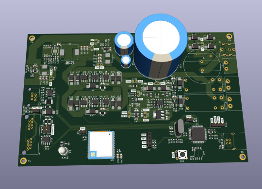
Let me introduce my current main WIP. It's not fandom related, it's for my model railroad, and it's not yet finished.
This is a rendering of a circuit board that I'm designing at the moment. It will be a DCC command station. My model railroad is run digitally, which means the tracks carry digital signals that tell each locomotive and switch individually how to run, which lights to turn and so on. The command station is the device that generates that. I have a number of different layouts, one of which has a good command station, one of which has a crappy old one, and the final one isn't even digital yet. So this will be the one that solves all issues for me, hopefully.
The design above isn't finished yet, and even the parts that are are not yet fully representative. The different capacitors are just there as options; some screen print overlaps; and some components (in particular all plugs and the relays that control the programming track) don't have 3D models so they don't show up.
Planned features:
Four layer board
10-25 V DC output, software controllable
Up to 5A output power, limited mainly by the main switching regulator.
Input 15-25V either AC or DC with polarity protection, selectable with some solder bridges (not yet in there). Optionally you can also bypass the main power regulator with another solder bridge (that I haven't added yet); useful in case you use e.g. a laptop power supply with a switchable voltage and don't need any regulation after that.
Railcom support
USB connection; not yet sure what for, but the main chip I'm using has USB support and I have some spare USB connectors here, so in it goes.
Speaking: The chip is an STM32L433RCT6P, chosen because I found it in stock at an electronics distributor. 64 kB RAM, 256 kB EEPROM, with support for an additional up to 256 MB externally (there's a spot for that on the board) and lots of fun extras that I don't technically need. It has an FPU! I don't need an FPU, but I will definitely do some floating point math computation on it just for fun.
Main external connection is WLAN using an ESP32 WROOM U module. I haven't decided on the housing, but I may go for extruded aluminum, so it's the U version that allows and requires an external antenna
It supports XBUS/XpressNet connections for old throttles from Lenz and Roco that I should probably throw away, but I paid good money for them, dang it.
It supports CAN for LCC / OpenLCB. I may not populate this part on all boards that I'm building, because I haven't actually decided whether I am interested. But the chip has CAN functionality built in, so why not.
There's an I2C connection to connect a cheap tiny OLED display for status messages.
Test points for all important signals (in particular the different internal voltage levels; yes, there is 3.3V, A3.3V and -3.3V and I need all of them).
Stuff still to add:
I will add pin headers (or space for pin headers anyway) for all the remaining pins on the STM32, and perhaps some on the ESP32, for future expansions.
Status LED and stop/go button on the front
Wire it all up, maybe move some stuff (mostly the STM32 around), which will cause all sorts of fun new routing issues.
Adjustments to make the jacks line up with the front panel once I've decided on a housing.
Features I'm not considering adding:
s88. I vaguely know what it is but I don't have any devices like that, and if that ever changed I could probably build (or perhaps buy) a converter that connects them via CAN.
Other buses like LocoNet.
Ethernet. I don't need it and it's actually more expensive than WLAN in this day and age.
In terms of software, I'm planning to use DCC-Ex on it. The whole project actually started out as a DCC-Ex shield, but once I realised that this wouldn't fit, I decided to make it standalone. Now, DCC-Ex is designed for Arduino, not STM32, and it doesn't support XpressNet, nor OpenLCB, nor Railcom, and their Wifi protocol is pretty weird and annoying which will be an issue (I'm planning to write my own control app for iPhone for it), so I'll probably change that or just replace it with the z21 one… so really, the software will not look a lot like DCC-Ex once I'm done with it.
Will this all work? I have honestly no idea. I mean, I'm fairly confident, I'd have given up on this long ago otherwise, but I have no guarantees either way until I've spent a lot of money on components and circuit boards and start soldering. Turns out doing it this way is not really cheaper than just buying a half-way decent one. That's what makes it exciting, though!
If it does work, obviously this will be released as open source. But it's still going to be a few days (more realistically weeks) before it's even ready to order the parts, and then a lot of soldering (current BOM stands at 194 actual components), and then a lot of software development before it's ready for that.
5 notes
·
View notes
Video
youtube
iot based agriculture monitoring pump on/off using arduino with Manual / Automatic | Smart Agriculture IoT Solution - IoT Sensors (Soil Moisture, Humidity, Temperature) | Smart Irrigation System | Arduino Uno | DHT11 | Humidity Sensor | Soil Moisture Sensor | Relay | GSM Based Motor Controller in Irrigation by Using Sensor's [ Soil Moisture Tank Water Level ] | SMS Based Remote Agriculture Pump ON/OFF Control and Notification | IOT BASED SUBMERSIBLE MOTOR PUMPS ON/OFF | IoT Based Agriculture Monitoring | pH | Moisture | Light | Irrigation | Rain | Temp | Humidity | IOT Based Agriculture Monitoring and Controlling System using Arduino Uno.***********************************************************If You Want To Purchase the Full Working Project KITMail Us: [email protected] Name Along With You-Tube Video LinkWe are Located at Telangana, Hyderabad, Boduppal. Project Changes also Made according to Student Requirementshttp://svsembedded.com/ https://www.svskits.in/ http://svsembedded.in/ http://www.svskit.com/M1: 91 9491535690 M2: 91 7842358459 We Will Send Working Model Project KIT through DTDC / DHL / Blue Dart / First Flight Courier ServiceWe Will Provide Project Soft Data through Google Drive1. Project Abstract / Synopsis 2. Project Related Datasheets of Each Component3. Project Sample Report / Documentation4. Project Kit Circuit / Schematic Diagram 5. Project Kit Working Software Code6. Project Related Software Compilers7. Project Related Sample PPT’s8. Project Kit Photos9. Project Kit Working Video linksLatest Projects with Year Wise YouTube video Links157 Projects https://svsembedded.com/ieee_2022.php135 Projects https://svsembedded.com/ieee_2021.php 151 Projects https://svsembedded.com/ieee_2020.php103 Projects https://svsembedded.com/ieee_2019.php61 Projects https://svsembedded.com/ieee_2018.php171 Projects https://svsembedded.com/ieee_2017.php170 Projects https://svsembedded.com/ieee_2016.php67 Projects https://svsembedded.com/ieee_2015.php55 Projects https://svsembedded.com/ieee_2014.php43 Projects https://svsembedded.com/ieee_2013.php1100 Projects https://www.svskit.com/2022/02/900-pr...***********************************************************Creating an IoT-based Smart Agriculture Monitoring System using Arduino can greatly improve the efficiency and productivity of farming. In this project, we'll use Arduino, various sensors, and an IoT platform like ThingSpeak or Adafruit IO to collect data and monitor the agricultural environment remotely. Here's a step-by-step guide to help you get started:Components Needed:1. Arduino (e.g., Arduino Uno or Arduino Mega)2. Sensors:• Soil Moisture Sensor• DHT22 or DHT11 Temperature and Humidity Sensor• Light Sensor (LDR)• Rainfall Sensor (optional)3. ESP8266 Wi-Fi module or ESP32 (for IoT connectivity)4. Relay module (for controlling irrigation systems)5. Power supply (solar or standard power source)6. Water pumps, valves, or actuators (for automated irrigation)7. Enclosure for outdoor installation (to protect electronics)8. Jumper wires, breadboard, and connectors9. Internet connectionProject Steps:1. Hardware Setup:• Connect the sensors and actuators to the Arduino using jumper wires.• Connect the ESP8266 or ESP32 to the Arduino using serial communication or I2C for data transfer.• Make sure all connections are secure and powered properly.2. Sensor Data Collection:• Read data from the soil moisture sensor to monitor soil moisture levels.• Use the DHT22/DHT11 sensor to measure temperature and humidity.• The light sensor can be used to monitor light intensity.• Optionally, include a rainfall sensor to measure precipitation.3. Arduino Programming:• Write Arduino code to read data from the sensors.• Implement control logic for irrigation systems based on the sensor data. For example, turn on/off water pumps or open/close valves.• Create a mechanism to send sensor data and control commands to the IoT platform via the ESP8266 or ESP32.4. IoT Integration:• Sign up for an IoT platform like ThingSpeak, Adafruit IO, or Ubidots.• Obtain the necessary credentials (API keys) to connect your Arduino to the platform.• Modify your Arduino code to send sensor data to the IoT platform periodically.• Set up dashboards and alerts on the IoT platform to visualize and analyze the data remotely.5. Remote Monitoring and Control:• Access your IoT platform's dashboard or mobile app to remotely monitor the agricultural conditions.• Implement automation rules and alerts to trigger actions (e.g., irrigation) based on specific conditions (e.g., low soil moisture).6. Power Supply:• Depending on your project's location, consider using solar power or a reliable power source to ensure continuous operation.
#youtube#IOT Based Smart Agriculture Monitoring Pump ON/OFF Control Using Arduino With Manual / Automatic https://www.youtube.com/watch?v=F3E0MiYCWpw
0 notes
Text
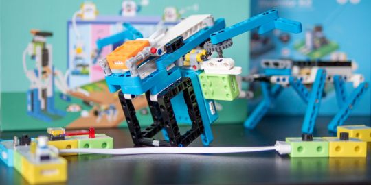
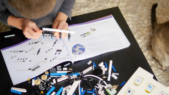
Elecrow Crowbits: The Ultimate LEGO-Compatible STEM Learning System That Grows With Your Child
Elecrow Crowbits
9.00 / 10
Read Reviews
Read More Reviews
Read More Reviews
Read More Reviews
Read More Reviews
Read More Reviews
Read More Reviews
Read More Reviews
Read More Reviews
Read More Reviews
Read More Reviews
Read More Reviews
Read More Reviews
Read More Reviews
Read More Reviews
Read More Reviews
Read More Reviews
Read More Reviews


Shop Now
Brick builds, combined with magnetic electronics blocks, and programmable micro-controllers. Does it get any better than this? I think my long search for the perfect STEM learning kit is complete. If you have young children just coming up to the right age for it, the Crowbits system can accompany them throughout their primary education and beyond.
Key Features
Magnetic blocks build circuits
Kits to suit various levels
Specifications
Brand: Elecrow
Development Platform: Scratch and MicroPython
Pros
LEGO-compatible to customize your builds
Full range of components planned
Level up with your child with more complex projects and programmable microcontroller
Familiar Scratch-based programming software
Cons
It's a Kickstarter
Instructions need work expanding on the principles and explanations
Buy This Product
Elecrow Crowbits other
Shop
// Bottom var galleryThumbs1 = new Swiper('.gallery-thumbs-1', { spaceBetween: 10, slidesPerView: 10, freeMode: true, watchSlidesVisibility: true, watchSlidesProgress: true, centerInsufficientSlides: true, allowTouchMove: false, preventClicks: false, breakpoints: { 1024: { slidesPerView: 6, } }, }); // Top var galleryTop1 = new Swiper('.gallery-top-1', { spaceBetween: 10, allowTouchMove: false, loop: true, preventClicks: false, breakpoints: { 1024: { allowTouchMove: true, } }, navigation: { nextEl: '.swiper-button-next', prevEl: '.swiper-button-prev', }, thumbs: { swiper: galleryThumbs1 } });
Take a moment to imagine the perfect electronics and engineering learning kit. It would be so simple even a child could use it: magnetic blocks, perhaps? Modular, so you could swap bits in and out to modify projects. It would scale up, so you could start with simple circuits and move on to programmable hardware, catering to all levels of the curriculum. Lastly, I'd throw in LEGO-compatible, because LEGO bricks are the best tool for creativity and engineering ever made.
That's exactly everything the Elecrow Crowbits system is, and it's crowdfunding now.
youtube
Disclaimer: This is a Kickstarter
Four of the five available Crowbits kits were sent to us for evaluation during the Kickstarter, however, they are still very much in the prototype stage, and we've evaluated them on that basis. Some bits were missing, some were non-functional, and the software is still a work-in-progress. This is to be expected at this stage, but the core system is solid.
Also, the usual Kickstarter caveat applies: your money is at risk, and there's no legal obligation with any crowdfunding campaign to actually deliver a product. That said, this isn't Elecrow's first campaign (the CrowPi 1 and CrowPi 2 were a huge success). It's a well-established company with a reputation to maintain and a good track record, so we think the risk is minimal.
What Are Crowbits?
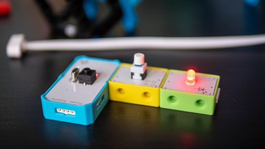
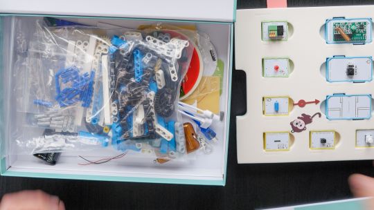
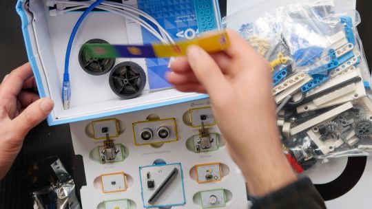
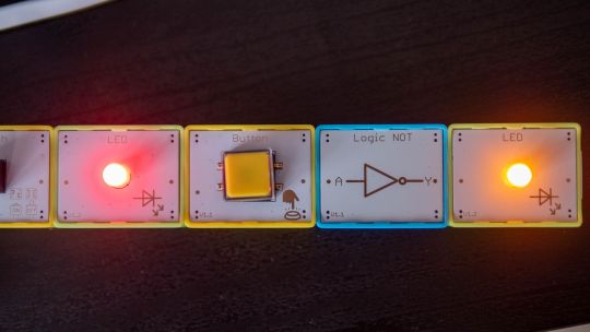
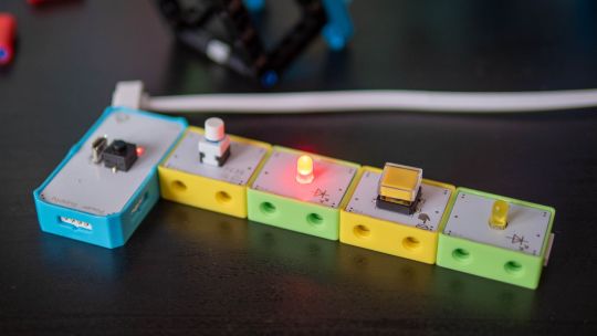
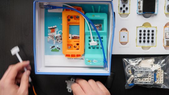
Crowbits modules are magnetic electronics blocks with LEGO-compatible pin holes on the side and stud holes underneath. The 4-pin pogo connections are either male or female, and have a small protrusion on the bottom to prevent wiring them the wrong way around.
Extension cables enable you to place a module elsewhere, and these too feature the same magnetic connection and can't be plugged in the wrong way. The whole system operates on a safe, low voltage, and with rechargeable battery blocks that charge over micro-USB.
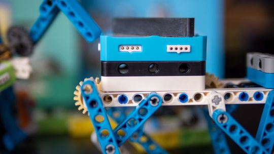
Each Microbits module is color-coded for ease of understanding:
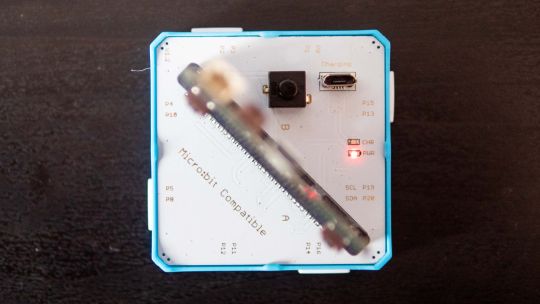
Blue modules are power and logic. In the basic sets, these are simple battery modules that don't require programming. In more advanced sets, these are programmable microcontrollers with pin numbers on the connections for addressing modules directly.
Yellow modules are inputs: buttons, basics sensors and such.
Green modules are outputs: LEDs, motors, buzzers, relays.
Orange modules are special and require serial communication lines to the programmable hub. These include things like color sensors, joysticks, or 2G communications hub.
A large range of Crowbits modules are planned, though these will be available separately at a later date. For now, you can only purchase the full Crowbits kits with their included module selections.
No Programming Required!
Since the first two Crowbit kits require no programming, how does that work? Simple, as long as you follow some basic rules:
Yellow input modules must be placed on the left of green output modules (when viewed with the module name being on the top, and symbol in the bottom right).
One input module can control a chain of output modules.
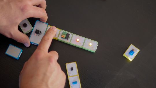
A new input-output chain will be created if you add another input module to the right.
Blue battery modules can go anywhere in the circuit, and their orientation doesn't matter as long as the pins are compatible.
With this, kids can create basic circuits. For more complex circuits (that still don't need programming), a series of bitwise logic operator modules are planned. A "NOT" logic gate is included in the Hello kit, and more will be available later.
This enables you to reverse an input, such that a button that would normally turn on an LED, would now function as a button to turn the LED off.
Crowbits Kits
The Crowbits Kits are divided into five stages of increasing complexity, but all share a common system and are compatible with each other. Some modules are duplicated between kits. Let's take a look at the contents and direction of each kit.
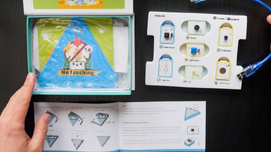
Hello Kit
The most basic of kits is also the cheapest, available for $30. It includes seven modules, one of which is a small battery module. Five project builds are included along with pre-cut cardboard parts to stick together. No programming is required, and the Hello kit is suitable for ages 5-6.
Explorer Kit
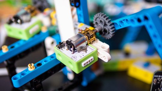
The Explorer Kit continues the no-programming theme, but adds movement through the use of a motor module and pack of technic pieces for some basic engineering. A total of eight modules are included, one of which is a medium-sized battery pack. The build guide contains a mix of brick-based and cardboard projects. With a little adult supervision on the trickier mechanical elements, 7-8-year-olds should be able to handle this kit. The Kickstarter price is $80, rising to $130 RRP.
Inventor Kit
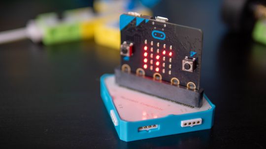
The Inventor Kit is a big step up that introduces programming concepts and more complex mechanical engineering. The main module of this kit requires a BBC Micro:bit (v1) to function. This is not included, though it may be available as an add-on if you don't already own one.
For those not familiar, the BBC Micro:bit is an all-in-one programmable microcontroller specifically designed for use in the school curriculum. It's widely used in UK schools, and gaining ground in the US.
Related: 10 Beginner Projects for the BBC Micro:bit
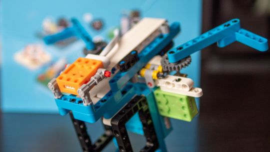
Ten modules are included as well as a large pack of technic bricks, suitable for building projects such as an obstacle avoidance car or color-sorting robot.
Given the use of BBC Micro:bit and Scratch programming in schools from around age 8, this kit would be suitable for 8-12 year-olds. It's available during the Kickstarter for $90, RRP $130.
Creator Kit
This was not yet ready for review at the time of writing, but the core of the Creator kit is an Arduino-based board, and includes 11 modules more suited to smart home projects and more complex interaction programming, along with a small selection of technic blocks. There are no movement motors. The Creator kit is available for $100 now, or RRP $150 later.
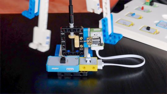
Master Kit
The most advanced kit in the range, the Master Kit uses an ESP32-based board at its core, featuring a TFT color screen. Also in the kit are some joystick modules, a small keyboard, laser ranging sensor, and 2G connection.
The Master Kit has a small number of technic bricks, and as well two silicone cases for a working phone, and a retro game console. It's designed to show the modules coming together to create a finished product. However, programming the firmware is quite complex, so I'd rate this kit as suitable for 14 and up. The early pricing is $100 for the Master kit, rising to $150 RRP.
LEGO-Compatible, not Actual LEGO
I should note that the Crowbits kits are not an officially endorsed nor licensed LEGO group product, and do not contain actual LEGO bricks. Instead, the LEGO-compatible technical bricks carry the brand name "CaDA", which I've not come across before.
That said, the bricks are well made and connect simply and securely, which is always a worry with off-brand construction bricks. For context, you can buy a set of at least 500 CaDA technic bricks on AliExpress for under $30.
You can of course decorate the builds with your own real LEGO, should you wish.
As a nerdy side-note, be warned that the instruction for the brick builds are read left-to-right, rather than top-to-bottom. If you're a LEGO family, this is mildly infuriating and means your child might skip steps!
Programming with LetsCode
Programming your Crowbits kits is done using Elecrow's new LetsCode (currently only for Windows, but support is promised for Mac OS and Raspberry Pi later).
LetsCode is a customized version of Microsoft MakeCode, which is itself based on the graphical block programming language, Scratch 3.0. As such, it'll be immediately familiar to anyone with experience of Scratch programming. It's widely used for introductory programming classes all over the world, and includes graphics blocks for all common concepts like loops, branching, and functions.
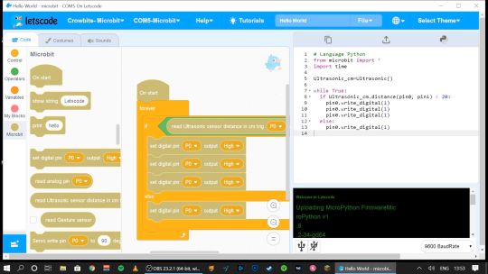
Pin numbers are printed directly on the blue modules, so it's easy to see which component is attached where.
If you outgrow graphical programming, you will also be able to program in MicroPython or Java, though this was not supported at the time of testing.
Should You Back the Elecrow Crowbits?
The Crowbits magnetic circuit system is easy to use and scales well for different ages and user levels. You can start with simple circuits, and move on to programmable logic controllers, and still reuse all the bits. It's a system that will grow with your child throughout their learning journey from age 6 to 14. Very few educational toys can make that sort of claim.
If you want your child to have a competitive edge in the programming, electronics, and engineering aspect of the STEM curriculum, then supplementing schoolwork is a great idea.
Even though many schools have now returned, it's possible you've opted to fully homeschool or just want to supplement their existing classwork. Over the next few years, schools will inevitably be different. There'll be a lot less practical work going on because of the aspect of touching shared equipment, so having this sort of kit available at home with software that's familiar will be of great benefit.
That said, the Crowbits kits vary greatly. If you're a completionist, you can grab a bargain bundle during the Kickstarter of every Crowbits kit available, for a cool $400 (rising to $600 RRP after the campaign).
But I think the best value comes from the Explorer, Inventor, and Master Kit bundle for $270. This includes a ton of mechanical bricks and plenty of movement modules. The BBC Micro:bit compatibility ties in perfectly to the existing curriculum (in the UK, anyway), while the ESP32 board is a good step up once they're old enough.
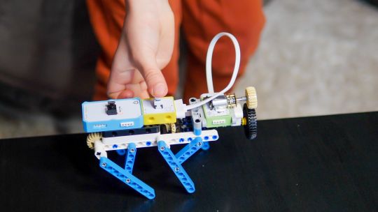
If you're only going to purchase one kit, I'd recommend skipping the Hello kit and going straight to Explorer or Inventor, depending on whether you want programming introduced yet. The cardboard projects in the Hello kit just felt a little too contrived and didn't engage my 6-year-old son in the same way LEGO does.
While the mechanical elements of the Explorer kit may need a little adult supervision, he was quite capable of the bulk of construction and able to use the LetsCode software thanks to previous experience with Scratch.
On the other end of the scale, I wasn't overly impressed with the Master kit either. The game console project, while it produces a cool end product, consists of simply the main board and two joystick modules on the side.
There is no construction, and the hardest part is loading on firmware, which tedious at best. The phone project is also impressive but limited to a 2G network, many of which will be disabled by the time the Crowbit kits ship. The ESP32 mainboard is technically impressive, but once your teenage child is ready to program this thing, the magnetic block system may not be appropriate anymore. It's a good addition to your collection if you're purchasing the earlier sets too, but I wouldn't purchase it alone.
Overall though, I think my long search for the perfect STEM learning kit is complete. If you have young children just coming up to the right age for it, the Crowbits system can accompany them throughout their primary education and beyond. And when they're done with it in a decade, we'll probably all be learning in VR anyway.
Alternatives to Crowbits
Crowbits isn't the only STEM kit around. The closest competitor is the littleBits STEAM kit, which retails at around $400, doesn't include any technic bricks, and has a limited selection of magnetic modules. It's more closely aligned to the US curriculum though with more extensive teaching materials, and already in use in many schools.
The LEGO groups' own Robot Inventor MindStorms kit is also worth considering, retailing at $350. It's focused more on robotics than basic electronics, and isn't suited to younger children, but the software is also based on Scratch. It would make a great step once your child reaches 14, and has outgrown the magnetic Crowbits system.
Elecrow Crowbits: The Ultimate LEGO-Compatible STEM Learning System That Grows With Your Child published first on http://droneseco.tumblr.com/
2 notes
·
View notes
Link
HOME AUTOMATION IN AUSTRALIA
The home automation device can be used to control anything in the home or an industry remotely. Each device has a relay and a solid state switch. External equipment's such as 240VAC (or 110VAC) light bulbs or a fan or a microwave or air-condition systems or anything similar can be connected to the device through the relay. These equipment's can, then, be controlled from remote using a smart phone or a computer. In addition, sensors such as temperature, humidity, motion sensors, ultrasound sensors can be connected to these devices. Almost all sensors available for Arduino can be connected to this device.
#home automation in Australia#best home automation#wifi secure access#Secure access#home automation#smart home automation
1 note
·
View note