#High current inductors
Text
High current power inductors, high power choke power supply
ETQ Series 48 uH 1.1 A 125 mΩ Unshielded Automotive Power Choke Coil Inductor
#Inductors#Power Inductors#ETQ-P5M470YFK#Panasonic#High current power inductors#high power choke power supply#smd power inductor#power inductors#Low profile SMD power inductor High current inductors#what is a power inductor#Power converters
1 note
·
View note
Text
Applications Where Linear Regulators
Are Preferable
There are many applications in which linear regulators or LDOs provide superior solutions to switching supplies, including:
Simple/low cost solutions. Linear regulator or LDO solutions are simple and easy to use, especially for low power applications with low output current where thermal stress is not critical. No external power inductor is required.
Low noise/low ripple applications. For noise-sensitive applications, such as communication and radio devices, minimizing the supply noise is very critical. Linear regulators have very low output voltage ripple because there are no elements switching on and off frequently and linear regulators can have very high bandwidth. So there is little EMI problem. Some special LDOs, such as Analog Devices LT1761 LDO family, have as low as 20μVRMS noise voltage on the output. It is almost impossible for an SMPS to achieve this low noise level. An SMPS usually has mV of output ripple even with very low ESR capacitors.
Fast transient applications. The linear regulator feedback loop is usually internal, so no external compensation is required. Typically, linear regulators have wider control loop bandwidth and faster transient response than that of SMPS.
Low dropout applications. For applications where output voltage is close to the input voltage, LDOs may be more efficient than an SMPS. There are very low dropout LDOs (VLDO) such as Analog Devices LTC1844, LT3020 and LTC3025 with from 20mV to 90mV dropout voltage and up to 150mA current. The minimum input voltage can be as low as 0.9V. Because there is no AC switching loss in an LR, the light load efficiency of an LR or an LDO is similar to its full load efficiency. An SMPS usually has lower light load efficiency because of its AC switching losses. In battery powered applications in which light load efficiency is also critical, an LDO can provide a better solution than an SMPS.
In summary, designers use linear regulators or LDOs because they are simple, low noise, low cost, easy to use and provide fast transient response. If VO is close to VIN, an LDO may be more efficient than an SMPS.
2 notes
·
View notes
Text
Myth-information
Like that word? I just thought of it.
I was meditating on the Frank Doris document linked in my previous post. The guy has gobs of experience, but that is tempered by his clinging to myths and misunderstandings to reach conclusions. There always has to be a conclusion.
I heard an effect it must be due to this thing. Or not.
So he likes planar speakers cuz they are low mass and such. Well if they truly were that they would have really good high frequency response and you know they don't. All current units have woofers and tweeter drivers as you do not have a practical true full range planar driver. There are two types of planar speakers. One is the magnetic like the Magneplanar. The other are various flavors of electrostatics. Skipping details he likes the sound (as do I) because they are low mass and fast (which they are not). But the truth is they are very inefficient and non-linear and not that low mass compared to a simple cone driver. The motors of cone drivers are much more efficient for a given mass of moving parts.
All planars either electrostatic or magnetic are non-linear. The forces applied to the diaphragm is from an electrostatic charge on grids or magnetic field which accelerates a thin sheet. BUT practical considerations require the diaphragm to be under significant tension which increases the restoring force the more the sheet moves from rest. A linear signal input gives you a not linear displacement. Effectively it is a signal compression. I know this as I have built them. But they still sound good.
Why do they sound acceptable and even very good? Well they have a large radiating area which couples well to the air in the room. An 8" speaker cone has 50 squinches of area. A modest planar speaker can have 10 times that. My electrostatics had 1500 squinches of area. That coupling is actually an impedance matching effect so the sound is put into the air very efficiently once it has got past all the mechanical limitations. It appears as impact and such. That goodness compensates for most of the inherent badness.
Big horn speakers share this impedance matching effect. The area of the horn outlet is the effective area of the speaker. In big Khorns you are talking square feet of area. But they have phase issues and horns distort, sorry.
There is no ideal speaker solution. Any method can be made to fool your brain. All have flaws.
Interconnect wires can effect sound. Not for the reasons noted in the marketing materials. I had a high end rather long shielded cable to link my front end to my amps back when I placed them right beside my speakers. (Audioquest brand) As they were shielded they were capacitors. Those very long runs dulled the high frequencies. I no longer need that length. I made a set of short cables by braiding four wires just long enough to reach between my preamp and my amplifier. It made a big difference. I cut the fancy cables to the same length and guess what they now sounded identical. Simple and cheap is fine.
All the bumf about speaker cables is bragging about how much money you can spend. Skin effect, time smearing, and all that does have an effect in radio frequencies but none at all in audio frequencies. The only factors that matter are inductance, resistance, and capacitance. All wires have those. Note that some very expensive audio electronics both produce and respond to radio frequencies due to design flaws. Don't buy that stuff. Just a simple heavy gauge wire is all you need.
Remember that the 20 odd feet of fancy speaker cables connects to maybe a hundred feet of fine voice coil wire and 60 odd feet of inductor wire inside your speaker box. The entire loop counts and adds together.
Insert rant here about fancy power cables. If they help, your equipment has a problem in the power supply. All that might change is your grounding condition and perhaps invalidating your fire insurance.
Oh and the eternal conflict between tubes and transistors. Yes that is a thing. They sound different while measuring the same. Does that prove that measurements are meaningless? No just they measure what they can measure. Skilled designers can make either sound like the other. But each tribe has its fan base and those people must be served. My tube amp is different here and there, but overall more similar to my transistor franken-amp than not. The differences are very small. And it is fun to explore.
Anyone who truly understands this stuff just rolls their eyes when the golden ears start to preach. I almost understand this stuff.
2 notes
·
View notes
Text

Smart Tweezers ST5S vs. Conventional Multimeter: A Smarter Choice
Smart Tweezers ST5S and conventional multimeters are both essential tools for electronic testing and troubleshooting. However, they differ significantly in terms of functionality and ease of use.
Smart Tweezers ST5S:
All-in-One Design: Smart Tweezers combine a set of high-precision SMD probes and a digital multimeter into a single handheld device. This streamlined design simplifies testing and eliminates the need for separate probes and multimeters.
Automatic Component Identification: One of the standout features of Smart Tweezers is their ability to automatically identify and evaluate SMD components. This saves time and reduces the risk of human error. The device can recognize resistors, capacitors, and inductors.
Ergonomic and Portable: Smart Tweezers are easy to handle and operate with one hand. Their lightweight and ergonomic design make them a preferred choice for professionals and hobbyists alike.
Real-Time Measurement: These tweezers provide real-time measurements, allowing users to monitor changes in component values as they troubleshoot. There's no need to disconnect and reconnect probes repeatedly.
LCD Display: Smart Tweezers feature a clear LCD display that shows component values and measurement results. It's easy to read and interpret, even in low-light conditions.
Conventional Multimeter:
Multiple Components: A conventional multimeter typically consists of separate probes and a central unit. It can measure a wide range of electrical parameters, including voltage, current, resistance, capacitance, and more.
Manual Range Selection: Conventional multimeters often require users to manually select the appropriate measurement range and function. This can be time-consuming, especially when testing various components.
Limited SMD Testing: While multimeters are versatile, they are less suitable for testing surface mount devices (SMDs) without the use of additional adapters or fixtures. This can add complexity to SMD troubleshooting.
Complex Readings: Interpreting multimeter readings can be challenging, especially for beginners. Users must understand the correct units, ranges, and measurement modes.
In summary, Smart Tweezers ST5S are a specialized tool tailored for SMD component testing, offering automatic identification and real-time measurements in a compact and user-friendly form. They are ideal for users who frequently work with SMDs. On the other hand, conventional multimeters are versatile devices suitable for a wide range of electrical measurements but may require additional tools for SMD testing.
The choice between the two depends on your specific needs and the types of components you regularly work with.
Quotation & Enquiries:
Contacts: Rajiv & Romesh
Cellphones: 9316134502 & 8283820745
Email: [email protected]
Alternative Email: [email protected]
2 notes
·
View notes
Text
Disadvantages of Mean Well LRS series power supplies
This post will not include information about power supply heating, ripple size, etc. Because it is all in the previous post: https://teardownit.com/posts/review-teardown-and-testing-of-lrs-150-24-mean-well-power-supply
In this post, I want to share a subjective and perhaps picky view about the LRS-200, and LRS-350 sources as a person, a user, not as a professional.

200 W

350 W
I have examined at least four revisions of these boards. The manufacturer made minor changes. Three transistor types were used at different times and in different batches (not depending on power). Thermal gaskets-caps were always used, even if the transistor body was plastic.
18N60M2 transistors. The transistors were installed in different packages (220), both in plastic and metal
6R280P6 transistors (plastic)
OSG65R290FE transistors. Package 220, plastic
I've only seen the identical diode arrays. The package is 220 metal; in the 24V version, it is metal and plastic.
Screw hole for the clamping bar screw
I think Mean Well made a mistake with the transistor clamping bar screw hole. If you try to tighten the screw any tighter, the clamping bar will turn out. Mean Well tightened the clamping bar as best they could and added a lot of thread locker. The hole should have been about 1/16" lower, and then there would not have been a problem. This also applies to the screw holes for the clamping bar screws for the diode arrays.
No second X2 capacitor
Now, about the reduced version of the input filter, namely for the second X2-capacitor absence, although a place for it is provided.

I think standardization and developers' fear of disturbing another department are to blame for this flaw :) The designer/developer made the correct diagram, but small details interfered. The diode bridge is fixed with a clamping bar, and the factory standardizes these bars and uses a bar from paired elements (transistors/diode arrays)). When the engineers started to install the board into the case, it was found that the standard diode bridge clamping bar interfered with the X2 capacitor case.
The developer needed to change the clamping bar type. But to do so, he had to contact another department, order it, etc. The developer may get a nasty remark from the manager, "Where did you look right away?" So, the engineer made a simple and ingenious decision—not to solder the second X2 capacitor at all. The cost of production was also reduced.

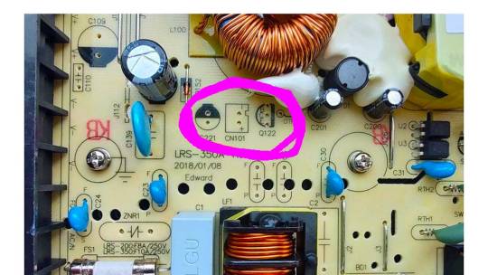
The power inductor
This element can be one of the hottest or the hottest on the board—up to 200F or more, depending on the power supply design.

The choke is generally made on some power supplies, with a gap with the near capacitor. This choke touches the capacitor on other power supplies (or batches). What is 200F on the capacitor?
Separation of the cold and hot board side
Now for a problem that has plagued Mean Well for several years. The manufacturer kept making changes to the boards, starting with just holes and then adding slots.
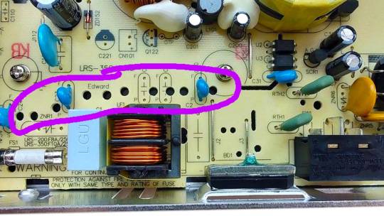
My speculation and assumptions. In 2018, developers made changes in a hurry, perhaps because of safety certification requirements or licenses to sell in some countries. Engineers made an almost continuous long slot from the input connectors to the optoisolator. In 2019, another revision of the board started to be produced.

The long slit severely weakens the board in bending and torsion; the board can break along the slit if dropped even from a low height (box in storage). The flaw was noticed by Mean Well, and after a few months, they are making changes again. The slit is getting short.

Differences between 200W and 350W versions
Different fuse rating
Different capacitance of high voltage capacitors for 200V (LELON). For 200W - 200V/330uF (18/35mm). At 350W - 200V/560uF (16/45mm). The board limits capacitors to 1 3/4" long (longer will interfere with the transformer)
Different ratings of current resistors
Different number of soldered capacitors on the output
Different number of soldered diode arrays. Except for the 24V version - diode arrays do not change with power (a surprising solution for me)
No fan in 200W version and no soldered fan assembly


Soldering quality
I advise checking the soldering of diode arrays with a magnifying glass and under good light. On two LRS power supplies, I encountered poor soldering of one of the diode arrays. However, I have no questions about the transistor soldering.
0 notes
Text
LMZ21701SILT Nano Module: Key Features and Specifications
The LMZ21701SILT is a compact nano power module from Texas Instruments, designed to simplify the power supply needs of small electronics. With its tiny footprint and efficient performance, it is ideal for space-constrained applications that require a reliable and efficient voltage regulator.
What is the LMZ21701SILT Nano Module?
The LMZ21701SILT is a step-down DC-DC converter (also known as a buck converter) that integrates several key components into a single module. This includes the controller, inductor, and passives, making it a plug-and-play solution for power management.
This nano module can output 1A of continuous current with input voltages ranging from 2.7V to 17V, while regulating the output voltage down to as low as 0.9V. Its small size, along with its built-in components, allows for a reduced component count and simplified design process, which is particularly beneficial for engineers working on compact devices.
Key Features of LMZ21701SILT
1. Tiny Form Factor
One of the standout features of the LMZ21701SILT is its incredibly small size. Measuring just 3mm x 3.8mm, it is perfect for applications where space is at a premium, such as wearables, portable electronics, and Internet of Things (IoT) devices.
2. High Efficiency
This nano module boasts an impressive efficiency of up to 90%, making it an energy-efficient choice for designs that prioritize low power consumption. The module's efficiency remains high across a wide range of loads, further enhancing battery life in portable applications.
3. Adjustable Output Voltage
The LMZ21701SILT allows for adjustable output voltages from 0.9V to 6V, giving designers flexibility when selecting the operating voltage for their devices. This feature enables its use in diverse applications, from powering low-voltage microcontrollers to supplying voltage to communication modules.
4. Integrated Protection Features
To ensure reliability, the LMZ21701SILT includes several protection features:
Thermal shutdown to prevent overheating.
Short circuit protection to safeguard against faults.
Overcurrent protection to handle excessive loads.
These built-in protections help extend the life of the device while preventing damage to the overall system.
5. Low Ripple and Noise
The module is designed to produce minimal output ripple and noise, which is critical for sensitive applications like medical devices, precision instrumentation, or audio equipment, where clean power is a necessity.
Applications of LMZ21701SILT
1. Portable and Wearable Devices
Thanks to its compact size and high efficiency, the LMZ21701SILT is ideal for wearables, smartphones, and other portable gadgets. Its small footprint allows it to be used in space-constrained designs, while its efficiency extends battery life.
2. Industrial Sensors and IoT Devices
In IoT applications, where devices are often deployed remotely and run on battery power, the low power consumption and versatility of this module make it a suitable choice. It ensures that sensors and other IoT nodes can operate efficiently for extended periods without frequent battery replacements.
3. Consumer Electronics
Consumer devices like smart home products, audio systems, and digital cameras can benefit from the LMZ21701SILT. It ensures stable power delivery with low noise, which is essential for devices that require consistent performance.
4. Embedded Systems
This module is also useful in embedded systems, where compact and reliable power delivery is crucial. Its adjustable output voltage makes it a versatile option for powering microcontrollers, communication modules, and other components in embedded designs.
Specifications at a Glance
Input Voltage Range: 2.7V to 17V
Output Voltage Range: 0.9V to 6V
Output Current: Up to 1A
Efficiency: Up to 90%
Package Size: 3mm x 3.8mm
Protection Features: Thermal shutdown, short circuit protection, overcurrent protection
Operating Temperature Range: -40°C to 125°C
Conclusion
The LMZ21701SILT Nano Module is a powerful and compact solution for efficient power management. Its tiny form factor, high efficiency, and integrated protection features make it an excellent choice for modern electronics that require reliable and space-saving power solutions. Whether you're working on wearables, IoT devices, or embedded systems, the LMZ21701SILT offers the flexibility and performance you need to create cutting-edge designs.
Understanding its key specifications and potential applications can help you choose the right module for your project, ensuring that your devices run efficiently and reliably.
0 notes
Text
LMZ21701SILT Nano Module: Key Features and Specifications
The LMZ21701SILT is a compact nano power module from Texas Instruments, designed to simplify the power supply needs of small electronics. With its tiny footprint and efficient performance, it is ideal for space-constrained applications that require a reliable and efficient voltage regulator.
What is the LMZ21701SILT Nano Module?
The LMZ21701SILT is a step-down DC-DC converter (also known as a buck converter) that integrates several key components into a single module. This includes the controller, inductor, and passives, making it a plug-and-play solution for power management.
This nano module can output 1A of continuous current with input voltages ranging from 2.7V to 17V, while regulating the output voltage down to as low as 0.9V. Its small size, along with its built-in components, allows for a reduced component count and simplified design process, which is particularly beneficial for engineers working on compact devices.
Key Features of LMZ21701SILT
1. Tiny Form Factor
One of the standout features of the LMZ21701SILT is its incredibly small size. Measuring just 3mm x 3.8mm, it is perfect for applications where space is at a premium, such as wearables, portable electronics, and Internet of Things (IoT) devices.
2. High Efficiency
This nano module boasts an impressive efficiency of up to 90%, making it an energy-efficient choice for designs that prioritize low power consumption. The module's efficiency remains high across a wide range of loads, further enhancing battery life in portable applications.
3. Adjustable Output Voltage
The LMZ21701SILT allows for adjustable output voltages from 0.9V to 6V, giving designers flexibility when selecting the operating voltage for their devices. This feature enables its use in diverse applications, from powering low-voltage microcontrollers to supplying voltage to communication modules.
4. Integrated Protection Features
To ensure reliability, the LMZ21701SILT includes several protection features:
Thermal shutdown to prevent overheating.
Short circuit protection to safeguard against faults.
Overcurrent protection to handle excessive loads.
These built-in protections help extend the life of the device while preventing damage to the overall system.
5. Low Ripple and Noise
The module is designed to produce minimal output ripple and noise, which is critical for sensitive applications like medical devices, precision instrumentation, or audio equipment, where clean power is a necessity.
Applications of LMZ21701SILT
1. Portable and Wearable Devices
Thanks to its compact size and high efficiency, the LMZ21701SILT is ideal for wearables, smartphones, and other portable gadgets. Its small footprint allows it to be used in space-constrained designs, while its efficiency extends battery life.
2. Industrial Sensors and IoT Devices
In IoT applications, where devices are often deployed remotely and run on battery power, the low power consumption and versatility of this module make it a suitable choice. It ensures that sensors and other IoT nodes can operate efficiently for extended periods without frequent battery replacements.
3. Consumer Electronics
Consumer devices like smart home products, audio systems, and digital cameras can benefit from the LMZ21701SILT. It ensures stable power delivery with low noise, which is essential for devices that require consistent performance.
4. Embedded Systems
This module is also useful in embedded systems, where compact and reliable power delivery is crucial. Its adjustable output voltage makes it a versatile option for powering microcontrollers, communication modules, and other components in embedded designs.
Specifications at a Glance
Input Voltage Range: 2.7V to 17V
Output Voltage Range: 0.9V to 6V
Output Current: Up to 1A
Efficiency: Up to 90%
Package Size: 3mm x 3.8mm
Protection Features: Thermal shutdown, short circuit protection, overcurrent protection
Operating Temperature Range: -40°C to 125°C
Conclusion
The LMZ21701SILT Nano Module is a powerful and compact solution for efficient power management. Its tiny form factor, high efficiency, and integrated protection features make it an excellent choice for modern electronics that require reliable and space-saving power solutions. Whether you're working on wearables, IoT devices, or embedded systems, the LMZ21701SILT offers the flexibility and performance you need to create cutting-edge designs.
0 notes
Text
Vishay Intertechnology has expanded its inductor product lines, offering customers a broader selection to achieve optimal cost/performance ratios. The new range includes high-inductance, high-voltage, and size-varied inductors, as well as improved noise reduction capabilities. This expansion caters to telecom, industrial, and consumer markets with products like wireless charging inductors, common-mode chokes, and high-current ferrite beads.
0 notes
Text
Troubleshooting Common Issues In SMPS Designs

Despite their benefits, switched-mode power supplies (SMPS), which efficiently convert electrical power switching between different energy levels, can have a number of design flaws. During design, development, and operation, SMPS may run into a number of issues like component failure, excessive noise, overheating, and instability. To ensure dependable and effective functioning, it is crucial to comprehend these issues and know how to resolve them. This blog includes a thorough analysis of typical difficulties with SMPS designs as well as practical solutions for their diagnosis and troubleshooting.
Common issues in SMPS designs
Common issues in SMPS designs can significantly affect performance and reliability.
Instability and oscillation: A fluctuating or oscillating output voltage and insufficient control are common indicators of instability and oscillation. These problems are usually caused by inadequate phase margin, an inadequate compensation network, or a poorly designed feedback loop. In order to debug, the feedback loop needs to be appropriately built with a phase margin, and the stability of the loop properly analyzed using simulation tools. The components of the compensation network need to be checked, and the values of the resistors and capacitors need to be altered as necessary. To find instability situations and make necessary design adjustments, the loads need to be tested.
Excessive noise and EMI: High levels of electromagnetic interference or audible noise from the SMPS might be signs of excessive noise and EMI. Poor PCB layout, insufficient filtering, or rapid switching transients are frequently the cause of this. The PCB layout needs to be optimized to reduce loop regions and stable ground planes need to be provided in order to solve these issues. By employing the right capacitors and inductors and by improving or adding input and output filters, filtering can be improved. To manage switching transients and lower noise, soft switching strategies and snubber circuits must be used.
Overheating: Thermal shutdowns and overheated components, including switching transistors and diodes, are frequent signs of overheating. This may be the consequence of inadequate thermal management, high power dissipation, or inadequate cooling. Cooling must be improved by installing fans, heatsinks, or better airflow to address overheating, and enough ventilation must be available. To minimize power dissipation, components with reduced on-resistance should be chosen. For optimal heat transmission from heated components to heatsinks or the chassis, thermal pads and conductive materials must be used.
Component failure: The SMPS may malfunction or behave erratically as a result of a component failure; frequently, observable damage to parts like capacitors, transistors, or inductors is present. Overvoltage or overcurrent situations, subpar or underestimated components, and high operating stress are common causes. Multimeters and oscilloscopes must be used to find electrical problems and components should be physically checked for damage as part of the troubleshooting process. To avoid stress and failure, outdated components with higher voltage and current ratings should be replaced, and heat, overcurrent, and overvoltage safety circuits should be installed.
Poor efficiency: High power loss and excessive heat generation might result from inefficient operation. Suboptimal design, excessive conduction losses, or ineffective switching are frequently the causes of this problem. Using high-efficiency MOSFETs and considering synchronous rectification can increase efficiency. By utilizing low-resistance components and making sure that PCB trace design is correct, gate drive circuits can be optimized to minimize switching losses and reduce conduction losses. To improve overall efficiency, the complete SMPS design should be reviewed and optimized, taking into account topology, component selection, and thermal management.
Diagnostic tools and techniques
The ability to detect and fix problems with SMPS designs efficiently depends on the use of diagnostic tools and procedures.
Oscilloscope: Because it enables engineers to detect ripple and noise levels on the output, measure voltage and current waveforms, analyse switching transients and noise, and diagnose SMPS issues, an oscilloscope is a critical diagnostic tool. An oscilloscope aids in identifying problems with signal integrity and stability by giving an image of electrical signals.
Spectrum Analyzer: For the purpose of locating electromagnetic interference (EMI) problems, a spectrum analyser is essential. It quantifies electromagnetic emissions, breaks down noise into its frequency components, and evaluates how well shielding and filtering work. This tool facilitates the identification of EMI sources and the assessment of the interference-mitigating effectiveness of the design.
Thermal Camera: Thermal management in SMPS designs may be evaluated with the use of a thermal camera. It assesses the efficacy of cooling methods, visualises temperature distribution, and finds hotspots. A thermal camera helps to avoid component overheating and optimise cooling techniques by detecting locations of excessive heat.
Multimeter: Finally, for simple electrical measurements, a multimeter is a useful instrument. It monitors voltages and currents, verifies component values like capacitance and resistance, and detects open or short circuits. Its functionality is crucial for confirming that parts are operating correctly and finding fundamental electrical problems with the SMPS design.
Effective diagnostic tools and a complete understanding of the underlying causes of typical difficulties in SMPS systems are required for proper troubleshooting. It is important to tackle issues related to instability, noise, overheating, component failure, and low efficiency to guarantee dependable and effective functioning. Significant improvements in SMPS performance and reliability may be achieved by using the right diagnostic tools and following best practices in design and testing. Improving SMPS designs requires constant learning and modification as technology develops. Coming to technological development, Miracle Electronics is a well-known SMPS transformer manufacturer in India, whose proficiency in creating dependable and technologically-advanced transformers guarantees best-in-class efficacy and longevity for a wide range of applications. Miracle Electronics provides solutions that satisfy the strict specifications of contemporary electronic systems, increasing efficiency and dependability in every design.
Resource: Read more
0 notes
Text
Common Mode Choke Amorphous Nanocrystalline Inductors
Features:
■ High saturation magnetic induction
■ Excellent wide frequency characteristics;
■ Extensive permeability adjustment range;
■ Better anti - unbalanced current capability;
■ Excellent temperature stability (high temperature); Low loss.
Formerly known as Hangzhou Hongci Technology Co., Ltd., it is China custom Common Mode Choke Amorphous Nanocrystalline Inductors suppliers and OEM Common Mode Choke Amorphous Nanocrystalline Inductors factory, we have independent core technology. Its annual sales volume is nearly 40 million. Its service customers include China State Grid, China Southern Power Grid, German Volkswagen, Schneider Electric, Siemens, ABB, Schaffner, Panasonic and other well-known enterprises.
Address
No. 8, Kangding Road, Wutong Street, Tongxiang, Zhejiang, China
Phone
+86-573-88985181
FAX
+86-573-88985081

0 notes
Text
Linear vs Switching AC to DC Converters: Which One Should You Choose?
Selecting the suitable AC/DC converter may appear complicated, particularly when determining between linear vs switching converters. Each type of converter has its benefits and drawbacks, and understanding the distinctions between them is vital to making the optimal option based on your requirements. In this short article, I'll clarify every little detail regarding direct and switched-over converters, contrasting the pros and cons of each so you can see which types of convert AC to DC power fit your needs much better. Whether you intend to run silently or successfully or discover a balance between the two, I'll assist you in comprehending the variables to consider when selecting a converter. By the end of the post, it will be clear to you the types of AC to DC converters and choose a converter. Let's get started!
Understanding the Basics: What Are Linear and Switching AC to DC Converters?
Linear converter:
This converter is like a power regulator, using transistors to control the voltage so that the device gets a stable direct current. They turn excess electricity into heat and keep the voltage from fluctuating. Because of its simple structure, it is very reliable and easy to use, especially for small equipment. They work quietly and have a stable voltage, making them suitable for powering sensitive devices that require precise voltage.
Switching converters:
These converters, also called SMPS, work differently. They use transistors and inductors that switch at high speeds to turn alternating current into direct current. This conversion is efficient and wastes almost no electricity. Switching converters can change the voltage and are used in many places, such as computer power supplies or large factory equipment.
In general, the linear converter is simple and accurate. Switching converters are efficient and versatile. With this in mind, you can pick the suitable converter for your needs.
Key Advantages and Disadvantages of Linear Power Supplies
The straight power supply is user-friendly, and troubleshooting is straightforward. Nevertheless, they create electromagnetic disturbance because of the absence of high-frequency buttons, impacting gadgets that call for noise-free surroundings. On the silver lining, the linear power supply provides stable and tidy voltage, making it ideal for gadgets with precise voltage needs.
Nevertheless, the negative aspect of straight power materials is that they are inefficient because they turn the extra electrical power into warmth to ensure that the electrical energy is lost. This is particularly real if you utilize it where you require a lot of electrical power or want to wait. The heat they produce as they function also makes the power source much heavier and may affect efficiency. Additionally, the straight power supply can only decrease the voltage and can not boost the voltage, so it is not appropriate for equipment that requires an increase in the voltage.
Why Choose Switching AC to DC Converter?
Advantages:
High efficiency: The switching converter uses less electricity, most of which can be converted into valuable electricity, so it is suitable for supplying power to equipment with large electricity consumption.
Small size: Because they don't turn excess electricity into heat, they can be made very small, unlike some older, larger power supplies.
Flexible: The switching converter can adjust the voltage, which can be raised or lowered, so it can be used in many different places, such as powering laptops or large machines.
Cons:
Complexity: Changing converters is complicated and needs a cautious layout, utilizing high-frequency buttons and additional parts such as inductors and capacitors. This intricacy can make style, issue searching for, and upkeep tough.
Electromagnetic interference: Switching converters may emit electromagnetic interference during operation, affecting other electronic devices. Good shielding techniques and suitable filters can help reduce this interference.
Noise: Switching converters are generally reliable, but they can produce some electrical noise when operating, affecting devices sensitive to electrical signals.
How to Decide: Factors to Consider When Choosing Between Linear and Switching Converters
Application Needs:
Consider the one-of-a-kind demands of your application. If you require a consistent, silent outcome for delicate electronic devices, you may locate a straight converter that is more suitable. Conversely, a switching converter could be more appropriate for managing higher power degrees or compact arrangements.
Performance Demands:
Evaluate precisely how essential efficiency is for your application. For energy-sensitive or high-power applications, switching over converters provides much greater performance and less heat generation, which can be essential for system efficiency and expense financial savings.
Dimension and Area Constraints:
Switching converters are commonly the far better selection if you're dealing with restricted space due to their compact size and effective warmth monitoring. Straight converters may call for more area because of their warmth dissipation demands.
Budget Evaluation:
While direct converters might seem more affordable initially, the general worth of a changing converter could be more significant when considering costs for extra cooling and prospective ineffectiveness, regardless of its higher first price.
Consider your ability to take care of complexity when picking between straight converters, which are easier to make, and switching converters, which require advanced layout methods and element selections.
Sound and E:
Direct converters may be preferable for applications that are especially vulnerable to electric interference because of their naturally reduced noise result. In contrast, changing reliability may demand additional style actions to alleviate electromagnetic interference.
Summarize
Choose between DC and switching power supplies based on your needs and critical factors such as efficiency, size, complexity, and noise. Linear power supplies are simple to use and suitable for low-power devices, but they are not efficient and heat up at work, so they are not ideal for all situations. The switching power supply has high efficiency, is small, and is suitable for high-power equipment or space-limited places. Still, their design is complex, and electromagnetic interference problems may exist.
You have to think about what your device needs based on the advantages and disadvantages of each power supply so that you can make a good choice. With the right power source, your device can get the power it needs, work well, and save money.
When deciding to convert AC to DC, it's crucial to consider these factors to choose the most effective converter for your application.
Read the full article
0 notes
Text
Exploring the Essence of Common Mode Inductors and Addressing Common Mode Interference Issues in Manufacturing Processes

Introduction:
In the field of electromagnetic compatibility (EMC), common mode interference is a significant concern, making common mode inductors one of the essential components we frequently utilize. This article aims to provide a brief overview of the principles and applications of common mode inductors.
Understanding Common Mode Inductors:
Common mode Inductors, also known as common mode interference suppressors, are devices with a ferrite core used to mitigate common mode interference. They consist of two coils of the same size and number of turns wound symmetrically on the same ferrite toroidal core, forming a four-terminal device. Common mode inductors exhibit significant inductance for common mode signals, playing a crucial role in suppressing such interference while having minimal impact on differential mode signals. Their operation is based on the phenomenon where the magnetic flux in the core adds up when a common mode current flows, resulting in significant inductance and impedance for common mode currents. Conversely, when a differential mode current flows, the magnetic flux cancels out, resulting in minimal inductance, allowing the differential mode signal to pass through without attenuation. Thus, common mode chokes effectively suppress common mode interference signals in balanced circuits without significantly affecting the transmission of normal differential mode signals.
LS8517CX Common Mode Inductor Balance Tester
Fabrication Requirements of Common Mode Inductors:
Insulation of Conductors: Insulation between the conductors during winding is necessary to prevent short circuits under transient overvoltages.
• Core Saturation: The core should not saturate when the coil carries transient large currents to maintain the normal operation of the common mode choke.
• Insulation Between Core and Coils: Insulation between the core and coils is essential to prevent breakdown under transient overvoltages.
• Single-Layer Winding: Coils should be wound as single-layer as possible to reduce parasitic capacitance and enhance the ability to withstand transient overvoltages.
Considerations in Common Mode Inductors Selection:
In selecting common mode inductors, it is crucial to consider both the desired filtering frequency range and the common mode impedance. Typically, a higher common mode impedance is preferred. Therefore, appropriate common mode inductors should be chosen based on the impedance frequency curve provided in the device datasheet. Additionally, attention should be paid to the influence of the common mode choke on the differential mode impedance, particularly in high-speed ports.
Conclusion:
As electronic devices, computers, and household appliances become increasingly prevalent, electromagnetic noise interference has become a significant concern, akin to a public hazard. In response, electromagnetic interference (EMI) filters have emerged as a new type of composite device widely utilized to suppress grid noise effectively and enhance the anti-interference capabilities of electronic equipment and system reliability. EMI filters find extensive applications in electronic measurement instruments, computer room equipment, switching power supplies, measurement and control systems, and other fields.
Read the full article
0 notes
Video
youtube
False Turn-On in MOSFET Driving Circuit and Countermeasures
MOSFET is a switch controlled by gate voltage.
When the gate voltage is greater than the turn-on threshold, the MOSFET is turned on; when the gate voltage is lower than the turn-on threshold, the MOSFET is turned off.
In actual applications, due to the influence of other factors such as device and peripheral circuit parasitic parameters, the originally turned-off power device may be mistakenly turned on.
Today, let's talk about the mistaken turn-on of MOSFET in the drive circuit and its countermeasures.
Let's talk about two cases of mistaken turn-on: mistaken turn-on caused by Miller effect and mistaken turn-on caused by parasitic inductance.
False turn-on caused by Miller effect
When the MOSFET is turned off and then turned on, the Vds voltage (the maximum voltage that can be applied between the drain and the source) rises rapidly to produce a high dv/dt (the rate of change of the drain-source voltage during the switching transient), thereby generating a displacement current (igd) in the capacitor Cgd (Miller capacitor).

This displacement current will generate a voltage spike after flowing through . If this voltage spike exceeds the turn-on threshold of the MOSFET, the MOSFET will be turned on, causing the circuit to be turned on or even damaged.
Another type of false turn-on is caused by parasitic inductance on the line. As shown in the figure below, Ls is the parasitic inductance on the source of the MOSFET.

When the MOSFET is turned off quickly, the current decreases rapidly to produce a high di/dt, and then a negative voltage (VLS) is generated across the two ends of the parasitic inductance. If this VLS voltage exceeds the gate threshold of the MOSFET, the MOSFET will be turned on by mistake.
So, what methods do we have to deal with the phenomenon of MOSFET being turned on by mistake?
1. Adjust the gate drive resistor and capacitor
The turn-on/off speed of the MOSFET can be adjusted by adjusting the size of the gate drive resistor and capacitor: increase the gate drive resistor and capacitor to slow down the turn-on/off speed of the MOSFET, reduce dv/dt (di/dt) and thus reduce the gate voltage spike.
2. Add a transistor
A transistor can be placed near the gate of the power tube to prevent false opening during the shutdown period, effectively suppressing the false gate opening caused by the Miller effect.
3. Use an anti-parallel diode
The current in the inductor can disappear through the diode loop, thereby avoiding the generation of reverse potential.
0 notes
Text
Review, teardown, and testing of RSP-150-24 Mean Well power supply
General description

A short description
The RSP-150-24 is a universal input power supply with a constant output voltage of 24 volts and a current of up to 6.3 amperes. According to the specification, it has an operating AC input voltage range of 85 to 370 volts without manual switching. The supply measures close to 7.8 × 3.9 × 1.2 inches (199 × 99 × 30 millimeters) and is made on a printed circuit board fixed to the base of the metal case, designed to operate with passive cooling. The top lid covering the case is perforated.
The power supply has an LED indication for the output voltage and allows one to adjust it within -5 to +10%. This unit does not have either PFC or thermal protection.
Design description
The input and output circuits of the power supply are connected to a common screw block (1). From left to right, there are three terminals for the input line, neutral, and ground wires, and two parallel blocks of two terminals for the outputs: ground and +24V.

The input voltage from the screw terminals is supplied to the RF interference filter (2) and through the fuse (3) to the diode bridge (5). Next, the rectified voltage is supplied to the active PFC, controlled by the PFC+PWM controller FAN4800 (4). The power part of the PFC is assembled using a MOSFET 19NM50N (6) and an 8A 600V ultrafast diode STTH8S06D (7). The output voltage from the PFC is supplied to the two-transistor forward converter, whose transistors, 14NM50N (9), are controlled by the same controller, FAN4800. The converter voltage from the transformer (10) is supplied to the rectifier and to the LC filter (13, 14). The output rectifier is made using MBR20150 diodes (12). The filter output capacitance is 470 uF, 35 V, designed for operating temperatures up to 220F (105C) (14).
General stabilization control is performed by the AP4310 chip. The control signal is transmitted from it to the high-voltage part of the circuit through a transistor optocoupler (15). One optocoupler serves as the main regulation channel, the second forms a backup channel for overvoltage protection (OVP), and the third provides reception of a remote control signal.
To limit the inrush current, there is an NTC (18) connected to the output stage of the rectifier bridge (5) near the boost inductor PFC.
The rectifier bridge (5), transistors, and diodes (6, 7, 9, and 12) are pushed against the housing with screws using overhead metal strips. Between the aluminum case and the board (from the solder side), there is an extra insulation layer, a thin sheet of fiberglass. All bulky components are additionally fixed using compound.
Build quality is good.
Test conditions
Most tests are performed using Metering Setup #1 (see appendices) at 80F (27C), 70% humidity, and 29.8 inHg pressure.
The measurements were performed without preheating the power supply with a short-term load, unless mentioned otherwise.
The following values were used to determine the load level:

Output voltage under a constant load

The high stability of the output voltage should be noted.
Power-on parameters
Powering on at 100% load
Before testing, the power supply is turned off for at least 5 minutes with a 100% load connected.
The oscillogram of switching to a 100% load is shown below (channel 1 is the output voltage, and channel 2 is the current consumption from the grid):

The picture shows three distinguishable phases of the power-on process:
1. The pulse of the input current charging the input capacitors when connected to the grid has an amplitude of about 4.5 A and a duration of about 5 ms.
2. Waiting for the power supply control circuit to start for about 50 ms.
3. (Output Voltage Rise Time) Output voltage rise takes 6 ms.
(Turn On Delay Time) The entire process of entering the operating mode from the moment of powering on is 61 ms.
(Output Voltage Overshoot) The switching process is aperiodic; there is no overshoot.
Powering on at 0% load
The power supply is turned off for at least 5 minutes before the test, with a 100% load connected. Then the load is disconnected and the power supply is switched on.
The oscillogram of switching to a 0% load is shown below:

The picture shows three distinguishable phases of the power-on process:
1. Charging the input capacitors when connected to the grid has an amplitude of about 1.5 A.
2. Waiting for the power supply control circuit to start for about 27 ms.
3. (Output Voltage Rise Time) Starting the converter, increasing the output voltage, and entering the operating mode take 4 ms.
(Turn On Delay Time) The entire process of entering the operating mode from the moment of powering on is 31 ms.
(Output Voltage Overshoot) The switching process is aperiodic; there is no overshoot.
Power-off parameters
The power supply was turned off at 100% load, and the input voltage at the moment of powering off was nominal. The oscillogram of the shutdown process is shown below:

The oscillogram shows two phases of the shutdown process:
1. (Shutdown Hold-Up Time) The power supply continues to operate due to the input capacitors holding charge until the voltage across them drops to a certain critical level, at which maintaining the output voltage at the nominal level becomes impossible. The phase takes 20 ms.
2. (Output Voltage Fall Time) Reduction of the output voltage, stopping voltage conversion, and accelerating the voltage drop take 6 ms.
(Output Voltage Undershoot) The shutdown process is aperiodic; there is no undershoot.
The current waveform at 100% load right before shutdown is close to sinusoidal with an amplitude of 2 A.
Output voltage ripple
100% load
At 100% load, the low-frequency ripple is approximately 15 mV.

At 100% load, the ripple at the converter frequency is approximately 50 mVp-p, and the noise is 70 mVp-p.

75% load
At 75% load, the low-frequency ripple is approximately 10 mV.

At 75% load, the ripple at the converter frequency is approximately 20 mVp-p, and the noise is 30 mVp-p.

50% load
At a 50% load, the low-frequency ripple is approximately 6 mV.

At 50% load, the ripple at the converter frequency is approximately 30 mVp-p, and the noise is 50 mVp-p.

10% load
At a 10% load, the low-frequency ripple is approximately 10 mV.

At a 10% load, the ripple at the converter frequency is approximately 30 mVp-p, and the noise is 50 mVp-p.

0% load
No-load current consumption measured with a multimeter: 29 mA.
(Power Consumption) The first assumption of excessive standby power draw of more than 6.5 watts is wrong, since the current in this mode is predominantly reactive. Indeed, the input filter in the circuit contains two capacitors with a combined capacitance of 1.5 μF.
Measuring the exact active power consumption at a 0% load with a basic set of instruments (oscilloscope, multimeter, etc.) is not possible.
At 0% load, the low-frequency ripple is approximately 2 mV.

At 0% load, ripples at the converter frequency are masked by the 80 mVp-p noise.

Dynamic characteristics
To evaluate the dynamic characteristics, a mode with periodic switching between 50% and 100% load was used. The oscillogram of the process is shown below:

It is clear that the power supply, when the load changes abruptly, allows for a slight dampening overshoot; the magnitude of the response to load changes is about 260 mV.
Overload protection
The claimed protection type is "constant current limiting, recovers automatically after the fault condition is removed." This was confirmed during testing. When the output is overloaded or shorted, the unit goes into current stabilization mode and automatically restores operation when the overload goes away.
The output current for the overload protection to kick in is 7.9 A.
Input circuit safety assessment
(Input discharge) Safety assessment is based on the discharge time constant of the input circuits when disconnected from the grid; the value is 0.126 s. This means that when operating on a 120 V input voltage, the time required to discharge the input circuits to safe values (<42 V) will be 0.2 s:

Important: The result is valid for this particular power supply unit; it was obtained for testing purposes and should not be taken as a safety guarantee.

The leakage current at the ground pin is 24 µA.
Thermal conditions
When operating with no load connected, no component overheating had been noticed.
Thermograms were captured at three power levels: 80, 90, and 100%, fully assembled and with the lid removed. Thermal images show that the most loaded element of the block is the input thermistor (NTC), and its heating seriously stands out against the background of all the other components. At 80% load, it heats up to 220F (104CC, 140F above ambient temperature). At 90%, it's 221F (105C, 141F above ambient), and at 100%, it reaches 236F (108C, 156F above ambient).
80% load


90% load


100% load


Conclusions
RSP-150-24 generally has little noise and ripple, the output voltage is maintained accurately, and the build quality is solid.
The dynamic characteristics of this unit aren't great; when the load pulses, the power supply can't adjust itself in time. This results in quite noticeable spikes and overshoots.
For long-term operation, the load should be limited to 70–80% of the nominal one., especially during the hot season when ambient temperatures reach 95F (35C) or more.
Important: The results are valid for this particular power supply unit; they were obtained for testing purposes and should not be used to evaluate all the units of the same type.
0 notes
Text
Essential Tools for Adjusting Voltage Regulators
Adjusting voltage regulators is a crucial task in electronics, ensuring that devices receive the correct voltage for optimal performance. Whether you're working on a simple project or maintaining complex equipment, having the right tools is essential for successful voltage regulation. This guide will walk you through the necessary tools and their uses, helping you achieve precise voltage adjustments.
Introduction
In the world of electronics, voltage regulators play a vital role in maintaining stable voltage levels for electronic devices. Whether you're a hobbyist or a professional, knowing how to adjust voltage regulators and having the right tools at your disposal can make all the difference. This guide will introduce you to the essential tools needed for adjusting voltage regulators effectively and safely.
Understanding Voltage Regulators
Voltage regulators are components that maintain a constant output voltage despite variations in input voltage or load conditions. They are used in various applications, from consumer electronics to industrial machinery. There are two main types of voltage regulators:
Linear Voltage Regulators: These provide a stable output with low noise, ideal for sensitive electronic circuits. However, they can be less efficient due to heat dissipation.
Switching Voltage Regulators: These are more efficient and suitable for high-power applications. They work by switching the input voltage on and off rapidly, using inductors, capacitors, and diodes to stabilize the output.
Why Adjust Voltage Regulators?
Adjusting voltage regulators is necessary for several reasons:
Optimizing Performance: Ensuring the device operates at its intended voltage improves performance and efficiency.
Preventing Damage: Proper voltage regulation prevents overvoltage or undervoltage, which can damage components.
Customizing Output: Some applications require specific voltage levels, necessitating precise adjustments.
Multimeters: Measuring Voltage Accurately
A multimeter is an indispensable tool for measuring voltage, current, and resistance. When adjusting voltage regulators, a multimeter helps you monitor the output voltage accurately. Here's how to use it:
Set the Multimeter: Choose the voltage setting and connect the probes to the output terminals.
Measure the Output: Read the voltage displayed on the multimeter to ensure it matches the desired level.
Monitor Changes: Use the multimeter to observe any changes as you adjust the regulator.
Oscilloscopes: Analyzing Waveforms
An oscilloscope is essential for visualizing voltage waveforms and analyzing signal behavior. It provides a graphical representation of the voltage over time, helping you detect fluctuations and irregularities:
Connect the Probes: Attach the oscilloscope probes to the input and output of the voltage regulator.
Observe Waveforms: Examine the waveforms to ensure a stable and consistent output voltage.
Identify Issues: Use the oscilloscope to identify problems like noise, ripple, or voltage spikes.
Soldering Irons: Making Secure Connections
A soldering iron is crucial for making secure connections when installing or replacing voltage regulators. Proper soldering ensures reliable electrical connections and minimizes resistance:
Heat the Iron: Allow the soldering iron to reach the appropriate temperature.
Apply Solder: Use the soldering iron to melt solder onto the connections, creating a solid bond.
Ensure Clean Joints: Inspect the soldered joints for any defects or cold solder joints that may affect performance.
Screwdrivers: Accessing Internal Components
A set of screwdrivers is essential for accessing the internal components of electronic devices. Whether you're removing a case or adjusting a potentiometer, the right screwdriver makes the job easier:
Choose the Right Size: Use the correct size and type of screwdriver to avoid damaging screws.
Remove Casings: Open the device casing to access the voltage regulator and other components.
Adjust Settings: Some regulators have potentiometers that can be adjusted with a small screwdriver.
Tweezers: Handling Small Components
Tweezers are invaluable for handling small components and wires when working on voltage regulators. They allow for precise manipulation without damaging delicate parts:
Grip Components Firmly: Use tweezers to hold and position small components accurately.
Avoid Static Damage: Opt for antistatic tweezers to prevent static discharge from damaging sensitive parts.
Heat Sinks: Managing Heat Dissipation
Heat sinks are crucial for managing heat dissipation in linear voltage regulators. Proper cooling ensures the regulator operates efficiently and prolongs its lifespan:
Attach Securely: Ensure the heat sink is properly attached to the regulator for effective heat transfer.
Monitor Temperature: Check the regulator's temperature during operation to prevent overheating.
Potentiometers: Fine-Tuning Voltage Levels
Potentiometers are adjustable resistors used to fine-tune voltage levels. They are often integrated into voltage regulators for precise adjustments:
Locate the Potentiometer: Identify the potentiometer on the regulator or circuit board.
Adjust the Resistance: Use a screwdriver to turn the potentiometer, adjusting the voltage output.
Verify with a Multimeter: Measure the output voltage to ensure it meets the desired level.
Testing Voltage Regulator Adjustments
After making adjustments to a voltage regulator, testing is essential to confirm stability and performance:
Power On the Device: Reconnect the device to the power source and turn it on.
Measure Output Voltage: Use a multimeter to verify the output voltage remains consistent.
Check for Stability: Monitor the device for any fluctuations or irregular behavior.
Conclusion
Adjusting voltage regulators is a vital skill for anyone working with electronic devices. With the right tools and knowledge, you can ensure that your devices operate efficiently and reliably. Whether you're a beginner or an experienced technician, understanding the tools and techniques for adjusting voltage regulators will enhance your ability to maintain and optimize electronic systems.
0 notes
Text
Capacitors in PE Power
Capacitors in PE Power are one of the most important exam topics. But why? The reason is their notable usage and importance in regulating and improving the Power circuits. Capacitors in PE Power involve studying their types, behavior, and uses in AC and DC circuits.
This detailed study guide on Capacitors in PE Power will help you cover this topic in complete detail as per the NCEES® exam guidelines and roadmap. Let’s start with the fundamentals.
Capacitors and Their Importance in Power Circuits
A capacitor is a passive electronic component that stores electrical energy in an electric field. It consists of two conductors separated by an insulator, known as a dielectric.
The capacity of a capacitor to store charge is measured in farads (F). It is determined by the physical characteristics of the capacitor, including the area of the plates, the separation distance between the plates, and the dielectric material used.
Capacitors are used in circuits for various reasons. Let’s discuss a few important uses in a nutshell.
Harmonic Mitigation with Capacitors: Capacitors are used in power systems to mitigate harmonics by creating resonant circuits that filter out specific harmonic frequencies. This is achieved by tuning the capacitor and inductor combinations to resonate at unwanted harmonic frequencies, thereby reducing their presence in the power system.
Capacitors and Voltage Fluctuations: Capacitors help stabilize voltage fluctuations in power systems by providing reactive power compensation. When connected to a power network, capacitors can absorb or release reactive power, which helps maintain a more consistent voltage level, especially in systems with fluctuating loads or significant inductive components.
Capacitors and Line Loss Reduction: By providing reactive power locally, capacitors reduce the need to transport reactive power over long distances in power lines, thus reducing line losses. This improves the efficiency of power transmission and distribution networks, as it decreases I²R losses (where I is current and R is resistance) in the conductors
Types of Capacitors
Capacitors come in various types and classifications, each suited for specific applications and characteristics. Here’s a detailed overview of the different kinds and classifications of capacitors:
· Electrolytic Capacitors
Aluminum Electrolytic Capacitors: They are known for their high capacitance-to-volume ratio; these capacitors use an aluminum oxide film and an electrolytic solution. They are polarized, meaning they must be connected with the correct polarity. Commonly used in power supply filtering applications.
Tantalum Electrolytic Capacitors: They are smaller and more stable than aluminum types; they have a lower risk of leakage and are more reliable. Tantalum capacitors are also polarized and are used in space-constrained applications like mobile phones and laptops.
· Ceramic Capacitors
Multilayer Ceramic Capacitors (MLCCs): They are composed of alternating layers of metal and ceramic and offer a compact and non-polarized size. Used in a wide range of applications, from high-frequency to general electronic circuits.
Disc Ceramic Capacitors: They are often used for noise suppression and are non-polarized. They are suitable for relatively low capacitance requirements.
For more information visit here: https://www.studyforfe.com/blog/capacitors/
0 notes
Last Seen Blogs

jeder-tag
my creativity is limited

bagelandcreamcheese1
Yo Wussup

baldwicons
hailey

oiks-tofu
Dipshit

adhyayknowledge
Adhyay knowledge