#How to Set Up a 5V Relay on the Arduino
Explore tagged Tumblr posts
Visit Tumblr Blog
Explore Tumblr blogs with no restrictions, modern design and the best experience.
Last Seen Tumblr Blogs


Fun Fact
Post activity is at the highest at 4:00 pm EDT; notes peak at 10:00 pm EDT.
Text
The future of smart home control begins with one sleek, powerful interface — the Nextion NX8048P050-011R 5.0” Intelligent Resistive HMI Touchscreen. Ideal for automation projects, this display offers unmatched user experience, intelligent processing, and seamless integration. If you're planning to level up your smart home or automation setup in 2025, this intelligent touchscreen should be on your radar.
Available now at www.sonoff.in, this module is a must-have for developers, hobbyists, and smart home enthusiasts.
Power-Packed 5.0” Intelligent Display for Smart Control
The Nextion NX8048P050-011R boasts a 5.0-inch resistive touchscreen, offering sharp visuals and precise touch response. Designed without an enclosure, this screen gives flexibility in mounting it into custom panels, enclosures, or control stations.
The resistive touch feature supports usage even when wearing gloves — making it practical for industrial, automation, and DIY applications. It’s a display that adapts to your environment, not the other way around.
Advanced HMI Capabilities Built for Efficiency
This is more than just a screen. It's a powerful HMI (Human Machine Interface) equipped with:
Onboard microcontroller for fast UI rendering
Rich GUI design with Nextion Editor
Easy drag-and-drop interface development
Support for static images, buttons, sliders, and dynamic text
Integrated flash memory for storing UI pages
You can build multi-layered smart interfaces without relying on external MCUs for rendering. Control everything from HVAC to lighting systems — with just a touch.
Streamlined Communication with Embedded Systems
The Nextion NX8048P050-011R communicates using UART serial communication, making it compatible with Arduino, Raspberry Pi, ESP32, and more. Developers love how it simplifies hardware-software interaction.
Commands are sent via a simple serial interface, which dramatically reduces processing load on your main MCU. This allows developers to allocate power where it truly matters.
Why It’s Perfect for Home and Industrial Automation
Here’s why the Nextion NX8048P050-011R is a game changer:
Compact but powerful – Fits in tight spaces while delivering advanced UI functionality.
Customizable UI – Create polished, user-friendly interfaces tailored to your smart home design.
Responsive Touch – Reliable performance in both residential and industrial settings.
Highly Compatible – Works seamlessly with Sonoff smart switches and automation modules from www.sonoff.in.
Whether you’re managing lighting, thermostats, or entire smart systems, this touchscreen gives you intuitive and elegant control.
Nextion Editor – No Code? No Problem.
The Nextion Editor software is a dream for non-programmers. You don’t need advanced coding skills to build dynamic user interfaces. Just drag and drop components onto your screen canvas.
From progress bars to image sliders, your interface can be as simple or complex as your imagination allows. With built-in event triggers, automation becomes a breeze.
Technical Specs at a Glance
Let’s dive into the core specs that make this touchscreen a powerhouse:
Display Size: 5.0” resistive touch panel
Resolution: 800x480 pixels
Flash Memory: 16MB
RAM: 3584 bytes
EEPROM: 1024 bytes
MCU: 48MHz
Serial Port: TTL UART
Operating Voltage: 5V
These specifications ensure smooth performance, fast response, and consistent reliability in demanding automation environments.
Installation and Custom Integration
Thanks to its open-frame design, you can install the NX8048P050-011R in custom enclosures or panels. Whether it’s a wall-mounted control panel or embedded into a furniture piece, the flexibility is unbeatable.
Pair it with Sonoff Wi-Fi switches or smart relays to create a smart home interface that looks and feels professional.
Smart Solutions, Smarter Shopping with www.sonoff.in
Looking for a reliable supplier in India? www.sonoff.in is the trusted destination for Nextion displays, Sonoff smart devices, and complete home automation solutions.
They offer fast delivery, excellent customer service, and authentic products backed by warranty. Get access to India’s top smart home gadgets — all in one place.
Conclusion: Smart Control Starts Here
The Nextion NX8048P050-011R 5.0” intelligent touchscreen is the perfect HMI solution for next-gen smart home setups. Its seamless performance, rich feature set, and compatibility with Sonoff devices from www.sonoff.in make it a standout choice.
Don't settle for clunky switches and outdated interfaces. Take control of your environment — the smart way.
Explore the future of home automation at www.sonoff.in and power up your smart living journey today.
#sonoff#smarthome#smartappliances#googlehomeintegration#alexacompatible#sonoffpowr3#homeautomation#sonoffindia#wifismartswitch
0 notes
Text
A Semi-Automatic Turntable: Part 1
Part 1: Intro & Subsystems
For a while now, I've been considering using an Arduino in order to automate the operation of the turntable on my layout. After considering several 'bolt-on' additions, I realised that trying to add indexing to the existing, DC-motor mechanism would be cumbersome. As such, I decided to replace the drive mechanism with a stepper motor, and use that for indexing.
My original plan was to just add indexing, with a keypad to select the desired track. But then I realised that I could take it a step further, and make it fully automated. This didn't quite work out, and I instead ended up with a semi-automatic version. This is how it ended up working:
youtube
I decided on this approach for two reasons: 1) I couldn't find sensors which would give me the accuracy required while being hidden. That is, there was always a trade-off between accuracy and visual impact. 2) My layout is a backwoods operation, with operating ground throws to change the turnouts.
As such, I wanted to have a hands-on element to the turntable's operation. While testing the fully automatic version, I found that I felt a bit 'disconnected' from what was happening. So in this series of posts, I'll be covering how I built this final version, and some of the things I learned along the way.
This first part will cover the construction and testing of the subsystems that make up the turntable controller. Some of these were built or adjusted after I'd decided to go from a fully automatic to a semi-automatic system.

I started by working out how to operate the stepper motor, a 12-volt NEMA-17 motor. This was the key to the whole system, and I'd never used one before. In order to drive it, the Arduino controls an A4988 chip. This is the red board in the photo above, with a silver heatsink on it. It takes a control signal from the Arduino, and a completely separate power supply for the motor itself. The only additional component required is the capacitor, to protect the inputs for the motor power supply, as well as a 10K ohm resistor to hold down the motor step pin when not in use.
The A4988 offers the option to drive the motor in 'microsteps', in which each pulse moves the motor by a fraction of a full, 1.8-degree step. Pins MS1, MS2 and MS3 on the A4988 are used to set which fraction is used. Setting them high, in various combinations, allows the A4988 to drive the motor in increments as little as 1/16 of a step. At this point in the build, I wasn't sure what resolution I would need. As such, I added a 4-way DIP switch between these three pins and the +5v rail, to allow me to try them. One of the switches from the DIP switch wasn't used.
Working from what I'd worked out on the breadboard, I built a motor driver board to be used in the final build.

My next step was to test that the motor had enough torque to move my locomotives. My heaviest locomotive is my boxcab, which was built on an Athearn blue-box mechanism. As such, it weighs in at around 450g.

I cut a length of wood to the same length as the turntable bridge. After finding the centre, I attached the driveshaft adapter I'd had 3D-printed by Shapeways. This fits around the shaft of the stepper motor, with a flat section where the drive shaft is flattened. It took a few tries at different sizes before it fit perfectly.

To simulate the load, I used a box of old motors I'd bought at a sale at my model train club. They were the only thing I had to hand which were heavy enough. I taped them to the top of the board, until it weighed 500g (for a bit of wriggle room). I then placed it on the end of the driveshaft.
youtube
The motor was able to move the load without any problems. With that confirmed, I started working on the components for the control panel.
The original, fully-automatic design had two 3mm LEDs on it, one red and one green. These were to have been 'stop' and 'go' signals for when the automated turntable was operating. The other component for the control panel was a 4-digit LED display to show the address of the currently selected locomotive. Owing to the change in focus for this project, the design of the control panel changed slighlty between the initial and final versions. But before I could build it, I needed to build the 4-digit LED display.

I'd done one of these on the base station for my DCC system. On that occassion, I'd made the display from four individual 7-segment displays, driven my a MAX7219 LED driver chip. This time around, I decided to use a 4-digit display, driven by the same chip. With the four digits in the one package, it only needs 12 connections for full functionality. I wired the 4-digit display to the MAX7219, leaving out the connections for the decimal points between the digits. They weren't needed.
To test it, I wrote an Arduino sketch (program) that counted up to 10,000 in 0.01 second increments and ran it. I was able to re-use a function I'd written for the base station, which will take a number up to 9,999 and display it across the four digits of such a display.
With that done, I was able to build the control panel itself.

When I decided to go from automatic to semi-automatic operation, I replaced the red LED on the panel with a single-pole, double-throw momentary contact switch. This is used to turn the turntable, via the stepper motor. I'd used a length of Cat5 network cable to connect the control panel to the Arduino, to keep things organised. This had a spare wire left in it. As such, I was able to wire the switch to the ground connection, then use the original wire for the red LED and the spare wire to connect to each side of it.

In order to get the program to work properly, there are a couple of points at which it pauses to prevent a false triggering while the locomotives move on and off the turntable. After initial testing, I realised it would make things clearer if there were an indication of when these pauses were occurring. So I added a yellow LED to the control panel, to indicate when the system was active. If this LED is on, then the turntable can be turned, locos can arrive and depart, etc. If it's off, then the system is paused.
Once completed, this control panel was installed in place of the original control panel on the fascia. The original panel had just had two switches, a DPDT rocker to control the DC turntable motor, and a 12-position rotary switch to select track power.

Next up was the occupancy detector, to determine when a train was on the bridge. The design of this turntable provides constant power to the tracks, with an auto-reverser reversing the polarity as needed. After a bit of experimentation, I found that wrapping the wire at least four times through the coil was enough to allow it to detect the current of a sound decoder at idle. At least, that's what I thought.
It's the first time I've used a coil like this, and it was sold amongst other Arduino modules. As such, I thought I would be able to plug it straight into an analog pin of the Arduino, and take a reading from that. This was not actually the case. As DCC is very close to AC current, I ended up getting several values from the coil over the course of a second, including 0, which would create false negatives. After asking about this on the Arduino forums, I learned that the way these coils work is by generating AC current, in response to the current going through them. I thought they just sensed it. As such, I'd accidentally been putting 38v of AC into the analog pin I was using, and had damaged it.

In order to use the coil for DCC occupancy detection, some supporting circuitry is needed. I found this article here, outlining how to build a sensor out of such a coil. I didn't have the exact same transistor, and instead used a BC548 NPN general-purpose transistor. The yellow wires off the board go to the two sides of the coil, and the green one goes to the Arduino.
Once I'd built this, I tested it with my locomotives before connecting it to the Arduino. This was where I discovered something interesting. The circuit is designed to give a digital output, in which anything less than 1.5v on the Arduino pin is counted as a 0, and anything above it as a 1. When testing it, I found that it produced an output of 3.7 volts when no locomotive was present, and that this dropped when one was detected. However, about half of my locomotives only dropped it to a value above the 1.5v required for a digital 0, yet less than the 3.7v of the 'nothing detected' state. As such, I connected it to another analog pin on my Arduino. These voltages translated to an analog read value above 900 when nothing was detected, and below 900 when something was. Thus, I used an analog reading with a threshold of 900 in the program function to detect occupancy.
At this point, the next item to be tested was a socket for an XBee wireless module. I'd already used these to make my DCC system, as well as to transmit the address of the incoming locomotive to my automated staging controller. As such, I pulled out a spare XBee, and configured it identically to the one for the staging controller. It'll be used for the exact same purpose, receiving addresses when a locomotive is dispatched. I tested it by connecting it to the Arduino, then rigging up the Arduino to display the received locomotive address on the LED display.

The next step was to prepare the Arduino shield. I usually use prototyping shields for the connections to the Arduino, as this means that I can just unplug the shield and pull the Arduino out if any software updates are needed. I've found it's easier to solder two wires together under the layout, than it is to solder to a shield. So I added small lengths of decoder wire to each output.
My turntable has 11 tracks around it, and I didn't have 11 spare pins on the Arduino. Instead, I used a 16-channel multiplexer with channels 1-11 wired to a bank of relay switches. I started counting at channel 1 instead of 0 in order to make the software code a bit simpler. The resistor on pin 4 is 220 ohms, and is connected to the green LED on the control panel. At this point, I hadn't added the yellow LED to the control panel. When I did, I added a 220 ohm resistor to pin 13, and connected this LED in there.
The other component of note is the variable resistor connected to pin A1. I was originally going to have a light detecting resistor in the turntable lead track, to trigger the Arduino when a train was leaving or arriving. However, after getting the occupancy sensor working reliably, the LDR was no longer needed.

The final building block was the relay bank. I'd bought a 16-relay module off eBay, and I installed it behind the fascia, next to the control panel. The wires from the original 12-way rotary switch to the tracks came out here, so by putting it in this position, I didn't have to do too much in the way of rewiring. Each track was wired to the normally-open contacts on the first 11 switches, with wires from the common side of the relay going to the track bus. The multicoloured ribbon cable on the far side of the relay bank goes to the Arduino, with two wires for the power supply and the other wires for the track control.
With all the building blocks worked out, the next step was to install the stepper motor and modify the turntable. This will be covered in part 2 of this writeup.
4 notes
·
View notes
Text
Biomed Grid| A Guide to Select Sensors for Biomedical Propose
Abstract
After Implementing an external device in a patient, it is crucial to monitor it. The challenge of being inside the patient and the need to perform the chirurgical operation to observe the evolution and state is a major step to do. Also, the communication process is not easy. On the top, the rejection avoidance of a strange body and the critical environment presents an additional motivation. The present paper presents a detailed study sensor for a wide range of biomedical proposes and applications. It aims to explain and synthetize complex technical knowledge in a simple and comprehensible language.
Keywords: Sensor, Monitoring, Nanotechnology, Biomaterials, Implants, Data acquisition, Medical
Introduction
In basic terms, the sensor is a device that makes the detection and responds with an input from the physical environment. But what could be these inputs? The light, heat, motion, moisture, pressure, or any detectable in an environment variable entry are examples. Thus, when a specific sensor receives input from the environment, it sends an output, generally a signal which is capable of being converted to be read by the processor or transmitted electronically through a data network. Sensors are associated with transducers, assembling measurements, supervising and control devices. They are used together. Sensor means a device que detects a change in the physical environment and transforms it into a signal que can be measured and recorded while the term transducer is defined as a device que transfers energy from one system to another, which may be the same as or converted form (other than the original). The sensor is applied to detect itself while the transducer is applied to the sensing element associated with any circuit. Figure 1 shows the cascade chain of the sensoring process[1].
Figure 1: Mitral Veg.
The sensors are used in a variety of applications in industries, services and even for households. Basically, the sensor is a device that has the function to detect and respond to any stimulus efficiency. Various types of sensors respond to different stimulus, such as: heat, pressure, movement, light and others. After the sensor receives the stimulus, its function is to send a signal that can be converted and interpreted by other devices. The choice of sensor depends solely on the purpose of its installation. So, one needs to assess environmental conditions and choose the most appropriate sensor for that activity.
Types of Sensors
Acoustic Sensor
This type of sensor uses the echo return That spreads the speed of sound, one of the sensor types used to capture distances. The acoustic sensor was used in Polaroid camera and is used in many studies That Work with sonar system. Another use of the acoustic sensor is in the parking system of the most modern cars (Table 1).
Table 1: Acoustic Sensor.
Electric Sensor
Table 2: Electric Sensor.
Electric sensors detect variations in electrical parameters such as an Increase in electric correte or even varying the voltage. These changes cause some sort of signal to change the status of a specific circuit, the relay switch. Use of this type of sensor is very common in voltage detection circuit, overcurrent or overvoltage protection relays (Table 2).
Magnetic Sensor
Sensors of this type are widely used to detect the opening of doors or windows. The magnetic sensor Consists of a small plastic box That has in its inside two metal blades fractionally spaced. The action of the magnetic field is precisely When They These blades close, allow current flow. This magnetic field is Obtained by a magnet! (Table 3).
Table 3: Magnetic Sensor
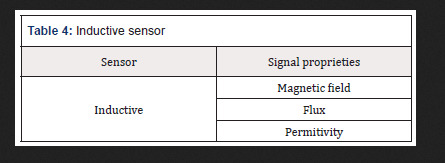
Inductive sensor
Are Also magnetic sensors sensors Inductive, These sensors create a small magnetic field at its tip and When the metal goes next to it disturbing the magnetic field, the cam sensor to capture this disturbance and sends a signal que can be interpreted by a circuit connected to the sensor (Table 4).
Table 4: Inductive sensor
Mechanic Sensor
These sensors are the ones who have the ability to detect the positions, movements or presence through mechanical means. Among the main applications, we can mention the presence of objects in a Certain place, the detection locks or door openings, and the limit switch sensor is one of the best known. The AIMS limit to Prevent sensing an engine to keep running even after the moving part reach the peak (Table 5).
Table 5: Mechanic Sensor
Optic Sensor
These sensors are also known as photovoltaic and use the propagation of light for its operation. The optical sensor is used to index objects and can also be used to measure the distance at which the object is in relation to the sensor. This type of sensor is used on elevator doors in computer mouse, bar code reader, in more modern vehicle reversing systems and many others (Table 6).
Table 6: Optic Sensor
Thermal sensor
This sensor gives a certain response when subjected to a temperature change. There are various types of thermal sensors and are several applications. The best-known thermal sensor is the thermometer that almost everyone has at home. It is used to measure body temperature. This type of temperature sensor is often used in environments where it is necessary to maintain a certain temperature, such as cold chambers. In this case, the sensor sends a response when it perceives that the temperature is outside of the ideal, and in accordance with this response refrigeration is switched off or activated(Table 7).
Table 7: Thermal sensor
It is important to know that there are specific sensors that fit within these mentioned groups which are the most common. There is a wide range of sensors for the most diverse applications. Following are some examples that may be used in devices embedded in the human body are presented. Indicative prices to be able to have an order of magnitude and make appropriate comparisons are presented [2,3]. The prices presented are based on historic benchmarking and experience of the author.
Proximity and Motion
The Distance ultrasonic sensor is capable of measuring distances of 2cm to 4m with great precision and low price. This module has a ready coupled to a receiver for measurement.
The reflection optical Reflective Phototransistor sensor is coupled in the same device has an infrared sensor (LED) and a phototransistor (receiver). It is specially designed to block light of other bands than the emitter itself, preventing ambient lighting interferences.
The Proximity Sensor Infrared is a photoelectric reflection module which includes an InfraRed (IR) transmitter and an IR receiver. This sensor has a longer range than traditional ones, ranging from 3 to 80 cm with the adjusting screw at the rear of the sensor.
The Absolute Orientation Sensor provides the possible to obtain the absolute position in three axes, useful to set up a project involving virtual reality [4-6].
The PIR Motion Presence Sensor can detect the movement of objects that are in an area up to 7 meters. If something is moving around in this area the alarm pin is activated.
The combined motion sensor on a single chip contains an accelerometer and a gyroscope MEMS type. They have 3-axis accelerometer and 3-axis gyroscope, providing 6 degrees of freedom (6DoF).
The obstacle IR sensor is a circuit composed by a transmitter, an IR receiver, and an IC comparator, which facilitates its connection with Arduino, PIC or Raspberry Pi, since its voltage is 3, 3-5V.
The Reed Magnetic sensor is a switch that works by magnetic field, closing the internal contacts when approaching. When taking the magnet, the contacts open again.
The Encoder speed sensor is used to perform engine speed measurements, pulse count and positioning controller. It can be used with many more drivers and boards such as Arduino, Raspberry Pi and PIC.
The Vibration sensor is designed to detect vibrations. Its applications are numerous but are mainly divided in a useful signal to process and a noise signal to remove. When the intensity is below the preset value (i.e., the value set at the potentiometer), the output is in a high state, otherwise the output is in the low state.
This Hall sensor has high sensitivity based on the Hall effect to measure magnetic fields around them. The magnetic signal is then converted into an electrical signal with high reliability and sensitivity and can be used in a very practical way with an Arduino. Alarms can be used in projects, accountants and other electronic circuits. The Grove magnetic sensor contains a reed switch on the board and can be used to set up alarm systems and proximity sensors based on magnetic fields.
The Vibration sensor Tilt Grove is used to detect movements and make the sign reading in a microcontroller as Arduino, Raspberry or Beaglebone plates and other applications in electronics design. The sensor can be used in monitoring systems and alarms systems, for example.
The gestures and RGB sensor are a plate with a sensor that provides ambient light measurement approach and signals. With Gesture Sensor and RGB it is possible to control a project, a computer design or a robot using only the movement of the hands.
The Distance Laser sensor is different from all the others: it uses a thin and invisible laser light source, and a circuit for detecting how long the light took to reach an object and return to the sensor. It can measure distances of between 30 and 1000mm with high degree of accuracy, has I2C and accepts power from 3 to 5V.
The analog line IR sensor varies the output value according to the amount of infrared light reflected to the sensor. When more light is detected by the IR receiver, the lower the voltage at the analog output.
The accelerometer module is a 12-bit resolution device with low power consumption, perfect for a virtual reality design using microcontrollers.
The Inductive Proximity Sensor is an NPN sensor capable of detecting metal objects up to 4mm away and generate a signal in the sensor output, which can be read by a microcontroller like Arduino.
The IR digital line sensor triggers the digital output according to IR light (infrared) received by the sensor. It is ideal for systems with only I / O available digital pin.
The 3-axis accelerometer has a new version provided now with a built-3.3V voltage regulator.
A Photo Interrupter Breakout Board was developed for easy connection to the component’s microcontroller. For complex projects involving accelerometer, gyroscope and magnetometer it is used an Absolute Orientation Sensor 9-DoF. It can be challenging to extract the necessary data of these sensors and convert them to a 3D world, requiring consolidating the data from these sensors, send them to I2C interface and saving work assemble complex algorithms or perform fine adjustments to extract the data needed.
For even more complex projects a 10DoF Sensor with Barometer, accelerometer, magnetometer and gyroscope is used. This is a powerful sensor IMU (Inertial Measurement Unit) that reaches 10 DOF, with 3-axis gyroscope, 3-axis accelerometer, 3-axis magnetometer and the pressure sensor and temperature.
Expected Price in March 2019 from €1.90 to €267.90
Temperature
The waterproof temperature sensor will allow you to take measurements in wet environments and wet with only one interface of one wire.
The regular temperature and humidity sensor allow temperature readings from 0 to 50° C and humidity 20 to 90%, widely used for projects with Arduino. The wider range temperature and humidity sensor allows temperature readings from -40 to +80° C and humidity from 0 to 100%, and very easy to use Arduino, Raspberry and other microcontrollers because it has only one output digital pin.
The temperature sensor with I2C communication is an accurate sensor, with typical accuracy of ± 0.25 ° C from -40° C to + 125° C + and resolution of 0.0625° C. The Temperature sensor is a sensor easy to use, communicating with the microcontroller via the I2C interface and sending temperature information in digital form, unlike traditional analog sensors. The Sensor Type K thermocouple with measuring range of -50 to 400° C is for use in multimeters and measurement equipment.
The temperature sensor can be a great option when looking for precision, and has easy communication with microcontrollers such as Arduino, PIC, ARM and Raspberry Pi. Widely used for home automation projects or even industrial.
The thermistor is a temperature sensor projects with widely used in microcontrollers, performing measurements in the range of -40 to 125° C based on a 10K Ohm NTC thermistor.
The temperature sensor Grove using a NTC thermistor for measuring the ambient temperature, generating an output voltage which is sent to the microcontroller.
The IR temperature sensor is a high-precision component that detects body temperature or objects by infrared without direct contact with the sensor is needed. It has already been calibrated at the factory and detects temperatures between -40 and 125° C with a precision of 0.5° C, still having multiple configurable user calibration methods.
The temperature and humidity sensor, for Sonoff is capable of measuring temperature and humidity providing data through its digital output. With its plug 4-pole, the sensor is perfectly compatible. The temperature and humidity sensor Son off have a resistive sensor capable of measuring temperature and a capacitive humidity sensor. Data is provided through its digital output. With its plug, the sensor is compatible with Sonoff TH10 / TH16. Sonoff is an affordable WiFi smart switch that provides users with smart home control.
The temperature sensor Waterproof Sonoff allows the functions similar to a thermostat, which can control any equipment according to the temperature.
The Digital Temperature Sensor performs temperature measurements accurately using only one pin of the controller.
The temperature and humidity sensor Grove is a module that contains a sensor on plate being connected to the microcontroller through a standard 4-pin cable Grove. This sensor comes pre-calibrated and is characterized by low power consumption and ease of use.
Expected Price in March 2019 from €2.40 to €80.90
Luminosity
The Brightness 5mm LDR (Light Dependent Resistor) sensor is a component whose resistance varies with the intensity of light. The lighter falls on the component, the lower the resistance. The light sensor can be used in projects with Arduino and other microcontrollers for alarms, home automation, motion, etc.
The Infrared (IR) receiver is useful in electronic projects such as motor control, lighting, alarms and circuits in general. It is user friendly with microcontroller circuit using Arduino, PIC or Raspberry Pi.
The IR Receiver Module is used in electronics design, remote control systems and alarms, for example.
The ambient light sensor module is a simple module to use but very powerful, as it has greater precision than standard modules using LDR (light dependent resistors). The sensor used is NPN phototransistor and the module has an analog output signal that can be read for example by a plate as Arduino. The higher the incidence of light, the higher the value in the output.
The photo Switch is an optical switch that operates with infrared, and on one side have an LED IR emitter establishing a light beam which is detected by the IR receiver on the opposite side. The distance between the transmitter and the receiver is 10mm.
The LDR Light Sensor (Light Dependent Resistor) is designed to detect light and has a digital and analog output that can be connected directly to a microcontroller as the Arduino.
The Infrared Phototransistor LED 5mm receiver is sensitive to infrared light and acts as a receiver of this type of light for use in electronics design as motor control, lighting, alarms and circuits in general. It is easy use with microcontroller circuit using Arduino, PIC or Raspberry Pi.
The UV Sensor is capable of detecting UV solar radiation using a simple chip. It can be easily configured for projects with Arduino to monitor UV Index, analyze UV-A lamps or DIY projects as plant growth analysis.
The Lux Light sensor can determine the amount of light (measured in lux), which is focusing on the sensor, and show that result in a display or trigger microcontroller ports in certain situations to light. Expected Price in March 2019 from €0.90 to €85.90.
Moisture
The humidity sensor Grove is composed of a rod and sends information to the microcontroller according to the humidity level detected by the sensor.
The Hygrometer Humidity Sensor is designed to detect the humidity changes, and when it is dry the sensor output is in the high state and low state when in wet.
The Rain Sensor is used to monitor a variety of weather conditions, but it can be used in liquid drops. When the surface is dry the sensor output is in a high state and when there is a liquid drop the sensor, output is in down state. Expected Price in March 2019 from €9.90 to €13.90.
Temperature and Moisture
The Temperature and Humidity High Precision Sensor and I2C communication with the microcontroller for use in electronics design, weather stations, room temperature control and medical equipment, among others. The sensor has 14-bit resolution and accuracy of 2% humidity and temperature of 0.2° C, providing accurate and reliable information as well as an extremely low power consumption in sleep mode. Expected Price in March 2019 around €65.00.
Chain
The Current Sensor Non-Invasive is an optimal device to measure AC current and is not invasive. It is widely used in projects with home automation Arduino like electrical current meters, protection of AC motors, lighting and others, but the non-invasive propriety is a boost to medical application.
The Current sensor performs current measurements accurately since it uses the Hall effect to detect the magnetic field generated by a current generating at the module output (OUT pin), a proportional voltage 66mV / A.
The DC Current Sensor provides measurements in circuits with DC voltage between 0 and 26V with DC current sensor, a I2C communication module and easy integration with devices such as Arduino, and other I2C interface. Expected Price in March 2019 from €26.90 to €58.90.
Touch
The Touch Sensor Capacitive is a component capable of detecting touches. Its operation is very simple: by touching the indicated region, the output of the sensor is activated. Without touching the sensor, there is no activity on output. It can be used as replacement of a push button.
The flexible sensor is a sensor of Sparkfun whose resistance varies as the sensor is bent. The greater the force applied, the greater the resistance in the sensor output.
The Force Sensor Resistive can make measurements between 100 g and 10 kg, depending on the force applied in the detection area (approximately a 15mm circle). Expected Price in March 2019 from €8.90 to €74.90.
Biometric
The Heart Rate Sensor allows to obtain data very useful when riding an exercise routine, studying daily physical activity or even for teaching purposes. The heart monitor pulse sensor performs reading of the heartbeat using an optical sensor amplified and sends this data to the microcontroller as the Arduino via a single signal pin.
The MyoWare Power Shield is a card designed for use with the Muscular Sensor MyoWare and uses two batteries. The Fingerprint Sensor can be used in projects with high complexity existing in this process.
The Muscular Expander Electrodes MyoWare Sensor allows you to place up to two electrodes directly on the board, being an interesting option for wearable designs (wearables). However, you often need a larger number of electrodes, or more distance between the electrodes and the sensor, and that’s where the Expander MyoWare electrodes. With Expander Electrodes Myoware, you can connectup to three electrodes using the cable MyoWare sensors (not included) connected to the expander through a P2 plug.
The Biomedical Electrode is the component responsible for forwarding to the sensor the electric signal captured during the movement of muscles. It can be connected directly to the Muscular Sensor or cable sensors.
The Sensor Muscular Myoware is a control device with the strength of your muscles. This is a plate designed for use with Arduino and using a sensor electromyography (EMG), which measures the electrical activity of a muscle. Muscular Myoware sensor generates at the output a voltage between 0 volts, and Vs, where Vs is the sensor voltage. The greater muscle activity, the higher the voltage at the output.
The cable Sensor is an accessory to be used in conjunction with the Expander electrodes and allows you to connect up to 3 electrodes in muscle sensor.
The strike sensor and Heartbeat Oximeter is a module consisting of two LEDs and a photodetector circuits that detect heart beats and indirectly measure the amount of oxygen in the blood. The sensor is suitable for projects in the medical field, fitness and wearables, among others. Expected Price in March 2019 from €12.90 to €374.90.
Barometric
The Pressure and temperature sensor have gains in terms of accuracy and power consumption beyond the size 63% smaller, making common their use in mobile and portable devices.
The Pressure and temperature sensor are fully compliant in terms of firmware and interface, including using the same Arduino library. It is a compact sensor with low power consumption (about 0.5μA), being a good choice for projects powered by batteries.
The Air Pressure Sensor measuring range of 0 to 40kPa and using MEMS technology miniaturization of components in a package DIP (dual in-line package). Expected Price in March 2019 around €20.00.
Others
TThe Water Flow Sensor measure water flow for your electronic projects is now no longer a problem with this Water Flow Sensor. It is installed in line with the pipe to measure the amount of water flowing through it, sending PWM pulses to your Arduino and Raspberry Pi for example. Expected Price in March 2019 around €35.00.
The Load Cell Weight Sensor uses the weight sensor load cell together with the module and build its own scale based on Arduino, Raspberry, or other PIC microcontroller. Expected Price in March 2019 around €20.00.
The Water Level Sensor is a liquid level sensor for use in water tanks, reservoirs, tanks and other containers. The level sensor functions as a power switch that can trigger switches, pumps, lamps or send a signal to the microcontroller as the Arduino, Raspberry Pi or Pic. Expected Price in March 2019 around €15.00.
The Color sensor detects the color of objects quickly and accurately with the color recognition sensor. The sensor recognizes light levels RGB (Red, Green and Blue, or red, green and blue) and sends this data to a microcontroller as Arduino, Raspberry, PIC and other models, allowing you to create efficient color detection systems. The Color RGB sensor with IR filter can recognize colors quickly and effectively. Based on chip, this sensor has RGB light sensors which together with the IR filter minimizes the influence of the IR spectrum, such as lights, leaving a much more accurate measurement. Expected Price in March 2019 around €65.00.
The sound sensor Grove is a plate with a microphone that detects the sound system and generates a variable signal at the output according to the intensity of the captured sound. Expected Price in March 2019 around €40.00.
Conclusions
There is a wide range of diferente sensors with diferente applications, advantages and strenghts. Knowing what best suits a real situation is crucial to extend life long. Also, it is important to understand how the sensor communicates the acquired data in order to find the appropriate acquisition and processing signal board.
Read More About this Article: https://biomedgrid.com/fulltext/volume2/a-guide-to-select-sensors-for-biomedical-propose.000583.php
For more about: Journals on Biomedical Science :Biomed Grid
#biomedgrid#Journals on Biomedical Imaging#Journals on Medical Microbiology#Journals on Medical Casereports#Journals on Medical drug and theraputics#Open Access journals on surgery
0 notes
Text
[Something awesome] iteration #6 [FINAL]
This is my last blog about my awesome project. There were so many problems happened along the way before I finished this blog. My Raspberry Pi got bricked 3 hours after I had finished integrating hardware and software components together. So I had no chance to record the video of it.
I spent fully 2 and days to reinstall the and set things up in my spare raspberry pi (As I mentioned in #5.5). However, it did not turn out as I had expected. Raspbian Buster, the latest version of the raspberry pi operating system, created for Raspberry Pi 4 which is the new model, is not 100% compatible with my model B+ and causes so many trouble while installing OpenCV module which takes 2-3 hours each time. It kept ending with error installation around 88-100% of the installation. I tried 5 different versions of this module (3.4, 3.4.1, 3.2.0, 4.0.0, 4.0.1) but all of them failed. I felt kind of regret that I did not take a video of my project before it got brick.
Fortunately, Last night at 3am, I decided to move on and looking for a way to make my software run in Arduino UNO in order to have some simulation to be shown in the presentation. Thanks to my Thai electrical engineering friend that guided me through this. So apart from how to do GPIO programming in python (for Raspberry Pi), I would write about how to control Arduino UNO through pyFirmata (module for python3) as another extension that was not mentioned in the proposal.
Redesigned Circuit

This is my new circuit connection. One more LED diode has been added and move the 5V DC source to NC side of the relay module. This would make the circuit to have 2 led color that can indicate door being locked or unlocked.
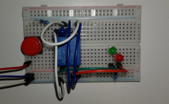
This is what it looks like in the real connection. It becomes way cleaner than the previous one having very messy wires and jumpers.

The green light indicates that the door is unlocked, while red is the opposite way.
GPIO programming for Raspberry Pi
Example of GPIO programming on Raspberry Pi
After I have both software and hardware prepared good enough to be put together, the time that I have been waiting for so long is here!
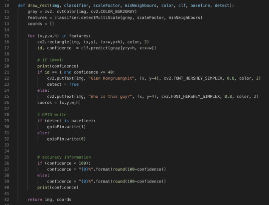
Let’s put them together and create a really cool facial recognition doorknob system. What I have to do is just set the digitalWrite signal to enable the relay module once my face is detected.
Firstly, the GPIO module is needed if this software is going to run on Raspberry Pi. It basically allows you to access all the pin on the board.
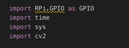
Next step is about to pick one pin as an output. The code below takes care of that.

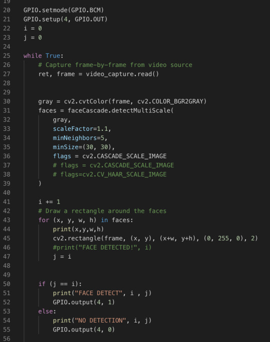
Then add a couple line of codes to make the pin to send digital output to the GPIO port in our circuit. A new code including line 22, 23, 41, and 50 to 55. It is very basic logic.
pyFirmata programming for Arduino UNO
This section is an additional one from having bricked Raspberry Pi. It is just to test that software and hardware can run together correctly because all of the computational parts are done by the laptop connected to Arduino. So the board is basically just a tool to send a digital signal to the circuit, no computation stuff at all.

So a module taking care of controlling the output pin in this time is pyFirmata. To do this you need to upload a standard program of Firmata into the Arduino board.

Arduino software provides you this program. You do not even have to learn how to code about this. PyFirmata is a program that changes your Arduino, that usually perform a software part, this burden is pushed to the high-level programming side (python in this time). So we can do everything, for example, reading and writing the pins.

The codes above have to be added into the main program of the recognition. It just specifies the port address connecting to the board, sets input and output pins.
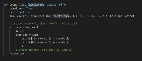
The first method is the detect. It is almost exactly the same as in iteration #5. The only difference is that I changed i and j into the boolean flags.
This is pretty much the same as last iteration’s code as well. Lines 28 to 32 are added. Just only 4 lines of code, we can have our system run on Arduino UNO! Isn’t it cool?
Running the program!
After all the time I spent on this project, this is the moment I have been waiting for. The facial recognition system that I created myself, got out of my comfort zone to build it from the scratch and researched heaps of self-learning. This video below could describe everything.
Video of the final result
Conclusion
This is a very long journey for me. I have learned a lot and my perspective of computer vision technology has been completely changed as well. I was really excited and proud of myself in the presentation today when I tested my program and shown it in the class. The reaction of everyone in the tutorial class made me feel like all the hard work paid off. Although my ways of explaining things are not that good, I hope you enjoy my blog and can gain at least some new knowledge from it. Cheers!
0 notes
Text
How to build a motion-controlled fan
New Post has been published on https://nexcraft.co/how-to-build-a-motion-controlled-fan/
How to build a motion-controlled fan
With this setup, you’ll never have to turn on your fan again. (Jeremy S. Cook/)
With summer in full swing in North America, finding a way to keep cool is a must. If you’re someone like me who relies on a fan to keep yourself from soaking your clothes in sweat, you’ve probably forgotten to turn it on, or simply wished it’d activate automatically the moment you walked in the room. Fortunately, with a bit of electronics hacking, you can get those fan blades whirring without having to flip a switch.
It’s a fairly simple project, too: just hook an Arduino Uno up to a motion sensor and an electronic switch called a relay, then plug in your fan, and you’re good to go. If that sounds complicated, don’t worry, we’ll walk you through it. And once you’ve got the hang of it, you’ll be able to apply the concept to lighting or anything else that plugs into the wall.
There are, of course, commercial smart home options available, but if you want total control over your system and something you can build upon, this is a great way to implement basic home automation.
What you’ll need:
<a href=”https://amzn.to/2H2rpxD”>Arduino Uno</a>
<a href=”https://amzn.to/2KtoujS”>Arduino Uno power supply</a>
<a href=”https://amzn.to/31yuA85″>Internet of things power relay</a>
<a href=”https://amzn.to/2YZkifF”>Passive infrared (PIR) sensor</a>
<a href=”https://amzn.to/2YYG1Ec”>Pre-wired male-to-male and male-to-female breadboard jumper wires</a> (length according to your setup)
Portable fan
<a href=”https://amzn.to/2H3azii”>Flathead screwdriver</a>
USB Type-A to USB Type-B cable
Enclosure (optional)
Wire the electronics
When everything’s plugged in, this is how your Arduino, motion sensor, and power relay should look. (Jeremy S. Cook/)
<p><strong>Plug the male-to-female jumper wires into the <a href=”https://www.popsci.com/how-to-use-motion-sensors/”>motion sensor</a> pins.</strong> The middle wire will be the signal line, and will connect to <strong>Pin 2</strong> on the Arduino. The side connector pins will go into the Arduino’s ground (<strong>GND</strong>) and <strong>5V</strong> sockets. These correspond with labels normally found behind the sensor’s white dome lens.</p>
<p><strong>Plug a male-to-male connector into a second GND pin on the Arduino.</strong> This wire will connect to the negative port on the power relay connector (labeled with a “minus” symbol). For wire installation, pull out the small green connector on the side of the power relay. Doing so will expose screws that open and clamp the wires.</p>
<p><strong>Plug another male-to-male connector into Pin 3 on the Arduino.</strong> This wire will connect to the positive port on the power relay connector (labeled with a “plus” symbol).</p>
<p><strong>Power your Arduino.</strong> To do so, plug the Arduino power supply into the <strong>always ON</strong> socket on your power relay, then connect the barrel jack on the other end of the power cord to the Arduino’s power input.</p>
Set up the Arduino program
At this point, your Arduino has the ability to sense movement and respond, but it has no program to tell it what to do. Let’s fix that.
<strong>Download the proper program for your computer from <a href=”https://www.arduino.cc/en/Main/Software”>Arduino’s software page</a>.</strong>
<strong>Run the program and follow the on-screen prompts.</strong> This will give it permission to modify your system.
<strong>Download <a href=”https://github.com/JeremySCook/IoT-Fan/blob/master/PIR-TurnOnMillis.ino”>this code</a> from my GitHub page.</strong>
<strong>Use Ctrl+O to load the code onto <a href=”https://www.popsci.com/how-to-understand-Arduino/”>the Arduino IDE</a>.</strong>
<strong>Connect your Arduino to your computer with the USB cable.</strong>
<strong>Use Tools>Board:>Arduino/Genuino Uno to choose the type of Arduino you’re using.</strong>
<strong>Use Tools>Port to select the port where your board is listed by name.</strong>
<strong>Use Ctrl+U to load the code onto your board.</strong>
How it works: The first few lines of the code define program variables and data storage locations. You’ll see PIRPin defined as “2” and OutPin defined as “3”—these correspond to where you plugged the PIR sensor and power relay into the Arduino.
The void setup() section defines the PIRPin as an input and the OutPin as—you guessed it—the output line connected to the relay switch. While this may be obvious, computers need to be explicitly told what to do. Perhaps the term “smart device” is a bit of a misnomer, as they need an intelligent human to set everything up.
The void loop() section, though, is where the real work occurs, as the Arduino loops this code repeatedly. First, it checks in with the motion sensor via PIRState=digitalRead(PIRpin) to see if has sensed any movement. Then, it records the number of milliseconds that have elapsed since the Arduino program began, with currentTime=millis().
<strong>(Optional) Change the delayValue.</strong> This bit of code dictates how long the fan stays on after the sensor notices movement. In my code, it’s set to <strong>600000</strong> (600,000 milliseconds, or 10 minutes). Tweaking this number will let you modify the fan’s behavior to your liking. If you only want it to run for 5 minutes, change the value to <strong>300000</strong>. The world is yours… as long as it involves turning on a fan.
How it works: When something triggers the sensor, the Arduino records that moment as triggerTime in Line 23, and compares it with the current time based on conditions in lines 26, 29, and 34. If the difference is less than the delayValue (10 minutes for the purposes of this story), the fan turns on or stays on. If the sensor detects movement during that 10 minutes, it tells the Arduino, and the timer resets. If the difference is higher than the delayValue, the program knows there hasn’t been any movement and turns the fan off.
Connect your fan and stay cool
You are now Lord of the Fans. (Jeremy S. Cook/)
<strong>With your fan unplugged, turn it on and set it to your preferred cooling setting.</strong>
<strong>Plug the fan into one of the two “normally OFF” sockets on the power relay.</strong> With everything connected, it’ll turn on automatically. You can even plug a light or another device into the other <strong>normally OFF</strong> port to make it motion-activated as well.
Optional: Build an enclosure
The setup will work as it is, but you probably don’t want a bunch of loose wires hanging around. There are a plethora of ways to mount your electronics, from Tupperware to a custom wooden box, but I happened to have a plastic electrical enclosure on hand. It has a plastic top that would seem ideal for motion sensing, but I’ve found clear plastic can interfere with infrared light.
What you’ll need:
Drill press (or <a href=”https://amzn.to/2KsJqHt”>a handheld drill</a>)
1-inch spade bit
Hot glue gun
1/2-inch drill bit (optional)
1/4-inch drill bit (optional)
<strong>Drill a 1-inch hole for the sensor.</strong> This is the only hole that needs to be close to spot-on, as it’s where the white semi-dome will protrude.
<strong>Drill holes for the power cable and hookup wires.</strong> Use the 1/2-inch bit for the power cable hole and the 1/4-inch bit for the hookup wire pass-throughs. You can also use whatever you have available that’s close, or even the spade bit if you’re OK with a loose fit.
<strong>Hot glue the Arduino in the center of the enclosure.</strong>
<strong>Hot glue the motion sensor to the hole you drilled for it.</strong>
<strong>Feed the wires through their respective holes and attach them to the Arduino and the power relay.</strong>
<strong>Reattach the enclosure’s top cover.</strong>
You can just leave the power relay on top of the enclosure, ready to use with your fan or whatever appliance you’re looking to trigger. Make sure the adjustment knobs for sensitivity and on-time for the motion sensor are facing up so you can modify how sensitive your device is and how long it stays on to signal your Arduino.
While great with a fan, this programmable switch you’ve created will work with other devices, too. So whether you’re looking to activate some lights, scare burglars who enter your tool-cave with a siren, or simply keep yourself cool, it’s a great gadget to have at your disposal.
Written By Jeremy S. Cook
0 notes
Link
I never really got in to Arduino, which is kind of surprising given my history. I have been playing around with micro processors for a long time. 30 years ago I had a door entry system running on a home made wire-wrapped 6502. I have coded things from tote betting ticket machines to mobile phones, and much more. I did loads on the PIC16C84 which was amazing when it came out, but somehow the Arduino passed me by. Of course, these days, there are the Raspberry Pi boards, which are similar in size and price to Arduino but powerful enough to run linux. I have used a lot of those. At the office we have loads running display screens, and doing things like network printers, and even the door entry and alarm system. Very powerful, but used generally as small network computers rather than hobby electronics with I/O. Even the alarm system uses the Galaxy RIO boards to do the I/O.
Arduino is stupidly easy
The Arduino eco system - the desktop environment - is really very simple and quite impressive. So much so that someone like my friend Simon, who knows bugger all about coding in C, is able to create working Arduino applications. It is impressive. The standard "Hello world" program is: (a) plug in the board, (b) click on arduino app, (c) type Serial.println("Hello World"); in the on screen setup() function, (d) click the arrow to flash... Done. In a few seconds you have a computer sending Hello World via a serial port. Making I/O pins do things is similarly simple. The coding is actually C++, which I have never been that happy with - but I am coping :-) What is very impressive is the community of hobbyists that has built up. There are libraries for everything, so if you want, say, to use a Dallas DS18B20 temperature sensor, you will find a library to do that and examples, and instructions how to wire it up. Indeed, even the Tasmota code I am using on my light switches has that built in so I can literally solder a temperature sensor on the the pads and click a few config settings on the web page to set it up. The libraries and examples mean that even Simon has been doing some impressive things, but he is not really a programmer, and so thought I might like a break(!) and spend a long weekend at his place. In some ways this is actually a slight problem - I found there are many competing libraries for lots of things and it is not always obvious which you should pick. Of course, I am making some apps and libraries to add to that!
Hobby hardware
Back in the days of a PIC16C84 you could get chips with actual legs on and solder wires to them! These days that is impossible - the chips and components are just too small. What is interesting is that there are now common "modules" that have such chips, with extra passive components, all in place on tiny PCBs with headers. As always the headers are 0.1" (2.54mm) pitch so you can use molex style pins and plugs (or even wire-wrap).
I would always have bought parts from RS or Farnell but I was shocked at what you can get from Amazon. I mean, seriously, it is mental. And unlike RS I can get stuff same day or on a Sunday (which was handy during this long weekend). Seriously, it is like finding your corner shop sells electronic components next to the sweets counter, I can't get over it!
Sensors everywhere! What is impressive is the hobby electronic devices you can get, on PCBs with 0.1" headers, it is mental. If I was asked to list possible types of sensor, I would not come up with nearly as many as you can get, and get on Amazon Prime even! Here are just a few.
3.3V and 5V
One of the things that takes some getting used to is that everything is 3.3V now. When I were a lad it was all TTL (5V). But even now it is not that simple as some things are 5V still, so you need level convertors. That said, some things are 5V only and will not work on 3.3V, some are 3.3V only and are damaged by 5V, and some things are designed to work at 3.3V or 5V.
Interestingly the ESP8266 (see below) is 3.3V, but rumours are that the input pins tolerate 5V. Apparently the CEO of the company that makes them said so on facebook, and people say it works. What does not work is powering the ESP-01, or similar, from 5V as the flash chip gets fried. The right thing to do is read the data sheet and use level convertors as necessary. The good news is that 5V to 3.3V and 3.3V to 5V power regulators are now small and cheap and so are level convertors, so easy enough to do it right.
Power
Another issue is powering things - I have always had to use a power supply in the past, a plug-top and lead of some sort. But of course there are USB 5V connectors everywhere now. That said, the regulators for such things are tiny now. The Sonoff devices work of mains with a simple on-PCB power supply so for many things you could use one of those as the processor! Powering off 12V, or 5V, is simple and a small PCB with regulator. Even powering off 1.5V or 3V is simple as well. It never used to be this easy, cheap or tiny! Apparently you can make apps that will run off a battery for years if you try hard.
ESP8266
The breakthrough for me really is the ESP8266 processor. It turns a small(ish) Arduino board with Ethernet and a plug top power supply in to some thing truly tiny, cheap, and interesting. The ESP8266 is a small processor which includes WiFi (albeit only 2.4GHz). This is amazing. It is sold in various packages, but the interesting ones seem to be the ESP-01 and ESP-12F. It is this processor that is in the Sonoff light switches. There seems to be good support for them under the Arduino IDE.
ESP-01
The ESP-01 is the basic entry level package for the ESP8266. It seems some were sold with ½MB flash but now they are 1MB flash (there are two chips on the module, the ESP8266 and the flash).
They are tiny, and have an 8 pin header. There are a whole load of boards designed just to work with the ESP-01, such as relay boards which have an 8 pin socket on the board (and come with an ESP-01). They cost 50p or so if buying from China, but are around £2.75 on Amazon. So easy to use.
For programming there is a nice UART / USB board you can get, which has the 8 ping socket for an ESP-01. The trick is to modify it to have a button on GPIO0, which has to be pulled low as you reset to put in programming mode. Simply hold the button as you plug it in...
ESP-12F
There are a range of modules from ESP-01, ESP-02, and so on. The ESP-12 series is interesting, and they have taken a different approach in some of these later modules - instead of 0.1" headers they have solder tags on the edge so the module can be soldered on to a parent board.
The ESP-12E and ESP-12F are the same apart from the antennae, and include 4MB of flash (which is nice). The ESP-12S is quite new it seems and slightly smaller and does not have some otherwise useless pins on the end (used for external flash). They also have a metal can for EMC, and claim FCC and CE approvals, which is nice too. There are, of course, nice breakout boards that provide the 0.1" headers. The main advantage (apart from CE marking, and 4MB flash) are that more of the ESP8266 pins are available, including the ADC input.
For programming you just need to connect the pins from the small UART board (GND, 3.3V, RX, TX, and the GND via a button for GPIO0).
I'll blog on some of the projects I am making later in the week.
via www.me.uk RevK's rants
0 notes
Text
How to Photograph Mysterious Floating Scrabble Letters
This past month, a student showed me an Instagram post with floating scrabble letters and asked me how it was done. After a few moments of reflection, I decided there was a number of ways to photograph floating letters and it would be a great idea for a student lab. To explore different techniques would be a great lab. The students evaluated the techniques to see which was best for creating floating letters.
The Scrabble letters are obtained from an online retailer that sold a large bag of letters for a reasonable price.
After several other experiments were tested, the best results were obtained by the “trapdoor” technique. This experiment was the students favorite and the technique I will explain here.
In the trap-door technique, the scrabble letters are arranged in a specially built box that has two doors on the bottom that swing open when a solenoid is energized. The trap door is an easy device to manufacture and the one I use was 3D printed, by eBay seller talos_crete. He sells the 3D printed drop box or trap door for around 50 dollars. The current arrangement only allows four letters to be dropped at a time. For larger groups of letters, a larger apparatus would be better.
The process is controlled by programming an Arduino processor to use a push button to start a clock and energize the solenoid which in turn opens the trap-door. After the letters fall the desired distance the high-speed flash is triggered to stop the motion. On this apparatus, the camera is set to bulb mode to catch the action, but future systems will be controlling a camera to take a picture at the correct time. This improvement will allow the system to operate in a room with the lights on.
The process is so stable that one of the students Ashley Crichton made a GIF:
The trap door ready to drop scrabble letters:
The circuit:
The switch resides on an electrical breadboard for this demonstration. When the switch is pressed, the Arduino pin 7 goes to a +5volt (high) value and this triggers the program to start.
I like to stress the power of a glowing LED to indicate the experiment is. This project is no exception. When the program starts up, the LED is turned on to show that something is working.
The next step that the program does is open a reed relay. This is basically a switch that allows the Arduino to control more voltage and current than can go through the microprocessor. Here the 5v DC reed relay opens a switch that allows the 12 VDC that the solenoid needs to open the trap-door. The reed relay also has the advantage that it isolates the 12VDC supply from the Arduino circuitry. The reed switch is not super-fast, but it is sufficient for this application.
To trigger the flash, I used an optical isolator that keeps the circuits from the flash trigger separate from the circuits for the Arduino. I could use a reed relay for this application, however, the opto-isolator is much faster. This also a nice way for students to be introduced to an optical isolator.
The circuit on a test breadboard.
In conclusion, the students decided that the trapdoor technique of dropping letters was the easiest and yielded the best results. The elimination of trial and error from the process allowed the students to get the letters in the exact position they desired every time.
Chris Marquardt from the podcast Tips From The Top Floor shows the technique. So many T and F to arrange – he mixed up the last two!
During the day, the students were experimenting, Chris Marquardt from the podcast Tips From The Top Floor made the following video of the process:
youtube
You can find the code here.
About the author: Ted Kinsman is an assistant professor of photographic technology at the Rochester Institute of Technology. He teaches advanced photographic technology, light microscopy, and macro photography courses. Kinsman specializes in applying physics to photography. You can find more about him and his work in his faculty profile and on his website.
source https://petapixel.com/2018/12/28/how-to-photograph-mysterious-floating-scrabble-letters/
0 notes
Text
How to Photograph Mysterious Floating Scrabble Letters
This past month, a student showed me an Instagram post with floating scrabble letters and asked me how it was done. After a few moments of reflection, I decided there was a number of ways to photograph floating letters and it would be a great idea for a student lab. To explore different techniques would be a great lab. The students evaluated the techniques to see which was best for creating floating letters.
The Scrabble letters are obtained from an online retailer that sold a large bag of letters for a reasonable price.
After several other experiments were tested, the best results were obtained by the “trapdoor” technique. This experiment was the students favorite and the technique I will explain here.
In the trap-door technique, the scrabble letters are arranged in a specially built box that has two doors on the bottom that swing open when a solenoid is energized. The trap door is an easy device to manufacture and the one I use was 3D printed, by eBay seller talos_crete. He sells the 3D printed drop box or trap door for around 50 dollars. The current arrangement only allows four letters to be dropped at a time. For larger groups of letters, a larger apparatus would be better.
The process is controlled by programming an Arduino processor to use a push button to start a clock and energize the solenoid which in turn opens the trap-door. After the letters fall the desired distance the high-speed flash is triggered to stop the motion. On this apparatus, the camera is set to bulb mode to catch the action, but future systems will be controlling a camera to take a picture at the correct time. This improvement will allow the system to operate in a room with the lights on.
The process is so stable that one of the students Ashley Crichton made a GIF:
The trap door ready to drop scrabble letters:
The circuit:
The switch resides on an electrical breadboard for this demonstration. When the switch is pressed, the Arduino pin 7 goes to a +5volt (high) value and this triggers the program to start.
I like to stress the power of a glowing LED to indicate the experiment is. This project is no exception. When the program starts up, the LED is turned on to show that something is working.
The next step that the program does is open a reed relay. This is basically a switch that allows the Arduino to control more voltage and current than can go through the microprocessor. Here the 5v DC reed relay opens a switch that allows the 12 VDC that the solenoid needs to open the trap-door. The reed relay also has the advantage that it isolates the 12VDC supply from the Arduino circuitry. The reed switch is not super-fast, but it is sufficient for this application.
To trigger the flash, I used an optical isolator that keeps the circuits from the flash trigger separate from the circuits for the Arduino. I could use a reed relay for this application, however, the opto-isolator is much faster. This also a nice way for students to be introduced to an optical isolator.
The circuit on a test breadboard.
In conclusion, the students decided that the trapdoor technique of dropping letters was the easiest and yielded the best results. The elimination of trial and error from the process allowed the students to get the letters in the exact position they desired every time.
Chris Marquardt from the podcast Tips From The Top Floor shows the technique. So many T and F to arrange – he mixed up the last two!
During the day, the students were experimenting, Chris Marquardt from the podcast Tips From The Top Floor made the following video of the process:
youtube
You can find the code here.
About the author: Ted Kinsman is an assistant professor of photographic technology at the Rochester Institute of Technology. He teaches advanced photographic technology, light microscopy, and macro photography courses. Kinsman specializes in applying physics to photography. You can find more about him and his work in his faculty profile and on his website.
from Photography News https://petapixel.com/2018/12/28/how-to-photograph-mysterious-floating-scrabble-letters/
0 notes
Text
Most of the times when we go out of home for some days, we think of having some device that could switch ON/OFF (let’s say) Refrigerator (or any other important appliance)for some hours during the day.
Today, we are going to make such time scheduled electric switch which switches ON/OFF at times which we set the in our Blynk app. Woah!
Let’s begin!
Things we need:

Components
Hardware:
5V relay
NodeMCU
Jumper wires
Breadboard
3V3 and 5V power source
Electrical Wires
Software:
Arduino IDE
BLYNK app
It’s circuit is same as we have created for our Smart Switch. So, if you already have that circuit set up, go ahead with Blynk app set up and Start playing.
Circuit:

Smart switch circuit
Connections:
D5 pin of NodeMCU connects to IN1 pin of 5V relay.
3V3 of NodeMCU connects to 3V3 powers source and GND to GND.
Vcc of relay connects to 5V source and GND to GND.
Live wire is connected directly to appliance.
Neutral wire from source comes to relay NC pin and another wire goes out from COM pin which is connected to the appliance.
Let’s set up the Blynk app:
Create a New Project in BLYNK app.
Write Project Name and Select NodeMCU from dropdown and WiFi as connection type.
An AUTH token will be sent to your registered email, note this down.
Tap on the screen and add the Eventor widget to the screen.
Tap on the Eventor widget and click Add New Event.
Select Time button and choose DAYS OF THE WEEK and START AT time and TIME ZONE. SET THE TIME, then tap OK.
Now, select turn ON pin and add D5 pin as we have connected our relay to PIN D5. Tap OK to finalize your Start Event.
Same way create a new event and select START time that will Switch OFF the relay at PIN D5.
#gallery-0-5 { margin: auto; } #gallery-0-5 .gallery-item { float: left; margin-top: 10px; text-align: center; width: 33%; } #gallery-0-5 img { border: 2px solid #cfcfcf; } #gallery-0-5 .gallery-caption { margin-left: 0; } /* see gallery_shortcode() in wp-includes/media.php */

Tap Eventor

Add New Event

Tap on time

Select pin and notification

Time pin and notification to turn off

Events added
We have completed the circuit and set up our BLYNK. Let’s do some coding.
Code:
#define BLYNK_PRINT Serial #include <ESP8266WiFi.h> #include <BlynkSimpleEsp8266.h> // You should get Auth Token in the Blynk App. // Go to the Project Settings (nut icon). char auth[] = "YOUR_AUTH_ID"; // Your WiFi credentials. // Set password to "" for open networks. char ssid[] = "WIFI_SSID"; char pass[] = "WIFI_PASSWORD"; void setup() { // Debug console Serial.begin(115200); Blynk.begin(auth, ssid, pass); // You can also specify server: //Blynk.begin(auth, ssid, pass, "blynk-cloud.com", 8442); //Blynk.begin(auth, ssid, pass, IPAddress(192,168,1,100), 8442); } void loop() { Blynk.run(); // You can inject your own code or combine it with other sketches. // Check other examples on how to communicate with Blynk. Remember // to avoid delay() function! }
Make sure to change the AUTH_KEY, SSID and PASSWORD before uploading the code to NodeMCU.
Upload and Play: Connect NodeMCU using the MicroUSB cable and upload the code using Arduino IDE.
Once uploaded, click Play button on the BLYNK app and we can now close the app. The app will do rest.

Upload and Play.
And yes, the button we added in our previous (Smart Switch Project) still works like a charm. So, scheduled or manual, everything is awesome!
Oh yeah!
We can now schedule our appliances to turn ON/OFF when ever we want. That’s what we call some good use of technology.
Suggestions and comments are always welcome. Feel Free!
Keep breaking, keep making!
Schedule turning ON/OFF of your home appliances with Blynk and ESP8266. #homeAutomation #IOT
0 notes
Text
New Post has been published on Weblistposting
New Post has been published on https://weblistposting.com/8-bit-breadboard-pc-is-up-to-8-hours/
8-BIT BREADBOARD Pc IS UP To 8 HOURS
[Ben Eater] posted some films of an 8-bit Computer and not using a CPU chip that he built absolutely on a breadboard a few years ago. After being requested for schematics, he ultimately admitted that he didn’t have any. So, instead, he decided to rebuild it and preserve a video log of every step in the manner. You can see his kickoff video, underneath, but You could additionally locate 30 more current motion pictures covering subjects from the ALU layout and troubleshooting to the decimal LED show. He even uses an Arduino to the application an EEPROM that he uses to update numerous logic.
BREADBOARD Pc
Breadboard Basics
You probably want to wait until you have a few unfastened time as there are around eight hours of movies to date. The videos start off with a simple 555 timer and work up from there. Every piece gets a test cut loose the entire, so with success, you gained have an not possible activity seeking to troubleshoot the entirety at the end.
Initiatives like this are decidedly impractical, however in case you ever need to truly understand how a CPU works, building one is a wonderful manner to expand that know-how. We’d advocate learning Verilog or VHDL and constructing on an FPGA, but the breadboard Laptop has a sure street cred and simply has a pleasing array of blinking lights.
The CPU design follows a design in the ebook “Virtual Pc Electronics” so in case you were severe approximately recreating this, you may follow alongside that, too. The e-book is out of print, but nowadays finding out of print books isn’t very difficult.
Styles of Prototypes: Basic Records
A prototype translates industrial thoughts into a tangible reality. A crew of highly skilled experts takes the specs of your entrepreneurial concept and the use of the present day CAD generation they caricature your thoughts. Then, with the help of Laptop simulations, those CAD drawings are translated right into a prototype that’s an exact copy of the final product.
Prototyping will assist you to get a correct and perfect operating version of your innovation, enabling you to weigh some exceptional alternatives, tweak them and subsequently provide you with a faultless design.
Industrial Prototyping
business prototyping produces absolutely practical prototypes fast and fees efficiently. This method may be used to produce a huge style of small and huge components utilized in industrial programs. business prototyping can reduce design time, trying out time and price. It offers higher visualization of products further to drawings and Computer fashions. This technique lets you keep away from assembling issues within the later ranges of manufacturing.
Rapid Prototyping
speedy Prototyping makes use of Pc technology to turn designs into three-dimensional gadgets. This technique is used for designing models in addition to prototyping components from an already drawn plan. This method can accelerate product development and make sure and faultless merchandise.
Breadboard: Breadboard builds a Primary running model of the final product. The Forms of prototypes crafted at this level may be used for speaking your design concepts to ability version-makers or producers so they get a higher idea approximately the appearance and sense of your final product.
Presentation Prototype: Presentation prototype creates a duplicate of the very last product which could paintings as a promotional material. This stage will display the functionalities of the product, but won’t be a genuine replica of the final product.
Pre-manufacturing Prototype: Pre-manufacturing prototype gives you a precise reproduction of the final product, enabling you to examine each component of the product in detail and discoverability design troubles earlier than launching the very last product. The drawings or photographs of this prototype may be used in brochures, mailings, pamphlets and advertising.
The finished prototype is a useful masterpiece. It is able to provide you a complete understanding approximately your actual product and assist you in discovering and correcting any problem that might arise at the later tiers of manufacturing.
The three-dimensional fast prototyping strategies will provide you a feel of truth and You can use them to sell your ideas to internal stakeholders. All the above-cited Kinds of prototypes can also paintings as powerful advertising and marketing gear.
What is Arduino? A Brief Observe the Arduino Platform
Desktop PC
Arduino is an open-source, programmable microcontroller and software program primarily based on the ATMega chip. Despite the fact that the Arduino is designed as a prototyping platform, It can be utilized in diverse electronics Initiatives whether brief or embedded. The Arduino board can be programmed the usage of the Arduino software. The syntax for that is similar to C/C++ and Java. It’s miles designed to be easy and easy to apply and can be operated with the aid of all people, from beginners to professionals alike.
As Arduino is an open supply platform, You could get preserve of the supply code and schematics for it. This indicates You could delve as ways into it as you want, even growing your own Arduino boards. There may be additionally a massive network at the back of it, and You can discover many tutorials and Initiatives from all around the global on line.
What can I do with an Arduino?
Quite much something you need! It has been utilized in such a lot of one of a kind approaches as the options are really unlimited. Beyond Projects have covered robots, artwork installations, in-car computer systems, MIDI controllers, cocktail makers, human-Laptop interfaces, Fb ‘like’ counters, advertising shows, clocks, tune tool, custom mouse and keyboard, domestic automation… The list goes on and on!
The primary capabilities of an Arduino board are its capacity to study data from sensors, to ship and acquire Virtual alerts and might connect through serial for your Computer. You may control much stuff, from LEDs and LCDs to automobiles and relays. You can also examine values from sensors together with potentiometers, mildly structured resistors (LDRs) and piezo.
The Digital pins on an Arduino can help you study or write 5v values. You can use a pin to turn on an LED (with a resistor). You can send a sign to a relay to function higher voltage home equipment like televisions and house lighting. You could ship messages to automobiles to show on and off. You may test to peer if a button has been pressed. You can even send and receive serial records, parallel information, and Virtual pulse width modulation. Essentially something that may be controlled via a bit of modern can be used.
The analog pins let you examine an incoming voltage between 0v and 5v. This will be the way you read from sensors. There is a mess of sensors available, from simple hands-on pressure sensors and rotary potentiometers to surroundings sensors together with stress, fuel, temperature or even alcohol. If you have, as an example, a slider set to exactly half of its range, it has to output a voltage of 2.5v. The Arduino can then read this and use the price to control something else.
You do not forestall with just controlling digital circuits. You could send statistics again to the Pc to manipulate software program which includes Processing and Max/MSP. You can send the records over USB with most models. some fashions have Bluetooth and Ethernet ports, and with additional shields (like an upload on the unit) You may communicate via WiFi and other protocols.
What cannot I do with one?
Bit meaning
The Arduino does not have lots of processing strength, so Pretty plenty any principal extensive mission is out of the query. You might not be capable of procedure, report or output video or audio (Although You can output pictures to TFT or Liquid crystal display screens). It is not like a Pc. You may not be capable of hook up your webcam or keyboard to it. There’s no operating system with a GUI (like a Raspberry Pi). It’s miles a completely unique beast.
0 notes
Text
Yo… yo… yo… Shippers! It’s been quite a few days that we have not built anything awesome. Come let’s gather up the stuff and get ready to roll.
Today, it’s time for smart switch which we are going to control over internet using our very precious BLYNK app. Cool!
Overview:
The 5V relay connected to D5 pin of NodeMCU goes ON when D5 pin is set LOW and relay goes OFF when D5 pin is set HIGH.
We are simply going to set D5 pin HIGH to turn ON the appliance and D5 as LOW to turn OFF the appliance, considering the neutral wire is passing through the NC and COM of the relay.
Stuff required:
Hardware:
5V relay
NodeMCU
Jumper wires
Breadboard
3V3 and 5V power source
Electrical Wires
Software:
Arduino IDE
BLYNK app
Circuit:
Smart switch circuit
Connections:
D5 pin of NodeMCU connects to IN1 pin of 5V relay.
3V3 of NodeMCU connects to 3V3 powers source and GND to GND.
Vcc of relay connects to 5V source and GND to GND.
Live wire is connected directly to appliance.
Neutral wire from source comes to relay NC pin and another wire goes out from COM pin which is connected to the appliance.
Technically, we are connecting our switch on the neutral wire of the appliance, which is turning ON/OFF the appliance. Simple!
Let’s set up our BLYNK app:
Create a New Project in BLYNK app.
Write Project Name and Select NodeMCU from dropdown.
An AUTH token will be sent to your registered email, note this down.
Tap on the screen and add a Button.
Tap on the Widget and select D5 pin, then change MODE to SWITCH. #gallery-0-8 { margin: auto; } #gallery-0-8 .gallery-item { float: left; margin-top: 10px; text-align: center; width: 33%; } #gallery-0-8 img { border: 2px solid #cfcfcf; } #gallery-0-8 .gallery-caption { margin-left: 0; } /* see gallery_shortcode() in wp-includes/media.php */
Create Project
Select NodeMCU adn WiFi
Add Button widget
Play the BLYNK button
Select PIN D5 and MODE as SWITCH
Auth Token
We have completed the circuit and set up our BLYNK. Let’s do some coding.
Code:
#define BLYNK_PRINT Serial #include <ESP8266WiFi.h> #include <BlynkSimpleEsp8266.h> // You should get Auth Token in the Blynk App. // Go to the Project Settings (nut icon). char auth[] = "YOUR_AUTH_ID"; // Your WiFi credentials. // Set password to "" for open networks. char ssid[] = "WIFI_SSID"; char pass[] = "WIFI_PASSWORD"; void setup() { // Debug console Serial.begin(115200); Blynk.begin(auth, ssid, pass); // You can also specify server: //Blynk.begin(auth, ssid, pass, "blynk-cloud.com", 8442); //Blynk.begin(auth, ssid, pass, IPAddress(192,168,1,100), 8442); } void loop() { Blynk.run(); // You can inject your own code or combine it with other sketches. // Check other examples on how to communicate with Blynk. Remember // to avoid delay() function! }
Make sure to change the AUTH_KEY, SSID and PASSWORD before uploading the code to NodeMCU.
Upload and Play: Connect NodeMCU using the MicroUSB cable and upload the code using Arduino IDE.
Once uploaded, click Play button on the BLYNK app and start turning ON/OFF your devices from anywhere in the world.
Play the BLYNK button
Oh Yeah!
That’s it for now, Shippers. See you in the next awesome IOT project.
Keep breaking, keep making!
Control switch over internet with BLYNK Yo... yo... yo... Shippers! It's been quite a few days that we have not built anything awesome.
0 notes