#Isometric drawing Guide
Explore tagged Tumblr posts
Visit Tumblr Blog
Explore Tumblr blogs with no restrictions, modern design and the best experience.
Last Seen Tumblr Blogs


Fun Fact
Tumblr was created by web developers David Karp and Marco Arment.
Text
Isometric Drawing Guide: Explained in 2024

Learn all about isometric drawing in 2024 with this comprehensive guide. Explore techniques, tips, and more. Isometric drawing is a method of graphic representation that allows for the visualization of three-dimensional structures on a two-dimensional plane.
This technique is particularly useful in the fields of architecture, engineering, and design, offering a clear and detailed view of an object from multiple perspectives without distorting the dimensions.
Unlike perspective drawing, which can appear more realistic but is complex to construct, isometric drawing simplifies the drawing process by maintaining a uniform scale in all directions, thus enabling easier interpretation and measurement directly from the drawing.
0 notes
Text
mumbo’s little concept art for his base is so cute i love it
#.lvblg#forgot to get a screenshot when i was up to him actually drawing it#ik he just used the isometric guide in procreate but the colours are very Pleasant#the vibes are immaculate#loving mumbo’s artist arc#then again videography/photography is an art form so. different flavour of artist arc
37 notes
·
View notes
Text

they tryin their damn best ⚡️
#the technical drawings I did for one of the in-game guide books for snacktorio are still some of my fav#and so wasted too like I did 7 of these bastards all in isometric#and you see them for like 5s#so damn right im gunna keep reposting them everywhere#game development#indie games#pixel art
12 notes
·
View notes
Text
🪷 Healing Astrology: Chakra Astrology 🪷
ᴄᴏɴɴᴇᴄᴛɪɴɢ ᴛʜᴇ ᴄʜᴀᴋʀᴀ ꜱʏꜱᴛᴇᴍ ᴛᴏ ᴀꜱᴛʀᴏʟᴏɢɪᴄᴀʟ ꜱɪɢɴꜱ
𝙐𝙨𝙚 𝙮𝙤𝙪𝙧 𝙎𝙪𝙣, 𝙈𝙤𝙤𝙣, 𝙖𝙣𝙙 𝙍𝙞𝙨𝙞𝙣𝙜 𝙥𝙡𝙖𝙘𝙚𝙢𝙚𝙣𝙩𝙨. 𝙊𝙣𝙡𝙮 𝙪𝙨𝙚 𝙝𝙤𝙪𝙨𝙚 𝙥𝙡𝙖𝙘𝙚𝙢𝙚𝙣𝙩 𝙞𝙛 𝙮𝙤𝙪 𝙝𝙖𝙫𝙚 𝙖 𝙨𝙩𝙚𝙡𝙡𝙞𝙪𝙢.


Taurus/Capricorn 2nd/10th house
Root Chakra: Stability, security, grounding, survival, safety, belonging
Exercise: Weightlifting, Resistance Band, Body Weight Exercise, Isometric Exercises
Hobbies: Gardening, camping, foraging, pottery, painting or drawing, knitting, woodworking, cooking, baking, journaling, meditation, candle making, farming, fishing, musical instrument.
Yoga: Hatha, Yin, Restorative, Vinyasa Flow, Kundalini Yoga
Dance: Soul Motion, African Dance, Tai Chi Qigong, Barefoot Dance
Crystals: Black tourmaline, hematite, red jasper
Essential Oils: Cedarwood, patchouli, sandalwood, vetiver, frankincense, pine, cypress,
Colors: Red, brown, green, beige, grey
Music: Listen to 396hz sounds, ambient, classical music, nature sounds, meditative music, folk and acoustic music, world music, jazz and blue, chanting and mantras
Healing foods for you: sweet potatoes, onions, carrots, radishes, beans, eggs, nuts, lean meats, oats, apples, strawberries, tomatoes, pomegranate, dark leafy greens, brown rice, quinoa, avocado, bananas, dates, seaweed.
Teas and Supplements:Ginger, cayenne, dandelion root, ashwagandha, chamomile, lemon balm, passionflower, lavender, nettle, l-thetanine, gaba, CBD, lions mane, reishi mushroom, kava.
Key Components:
• Have a bedtime and a wake-up time
•Live below your means
• Create a savings for a rainy day
• Find ways to organize your space
•Carry a journal with you
• Make a list of your favorite foods so you can always have an idea of what you want to eat
• If you want to buy something make a goal before you can buy e.g do a ten minute run everyday for a week to be able to buy a new backpack.
• Go to spas, get a massage
Cancer/Scorpio 4th/8th
Sacral Chakra: Connection with others, pleasure, emotions, sexuality, sensuality, creativity
Exercise: Boxing, kick boxing, HIIT, Zumba, Running or sprinting, Weighted workouts, Plyometrics, Swimming
Hobbies: Writing fiction, poetry, journaling, painting or drawing, digital art, improvisational acting, music composition, jewelry making, filmmaking, podcasting, photography, mythology creation, cooking or baking, astrology or tarot, cosplay.
Yoga: Yin Yoga, Restorative Yoga, Tantric Yoga, Kundalini Yoga
Dance: Contemporary Dance, Argentine Tango, Salsa, Belly Dance, Bachata, Flamenco, Rumba, Pole Dance, Jazz Dance, Freestyle
Crystals: Amethyst, Rose Quartz, Moonstone, Black Turmaline, Smoky Quartz, Carnelian, Lepidolite, Citrine, Sodalite, Clear Quartz, Labradorite
Essential Oils: Rose, Ylang Ylang, Jasmine, Sandalwood, Lavender, Vanilla
Colors: Orange, Coral, Amber
Music: R&B, Soul, Jazz, Classical/Instrumental, Flamenco, Ambient/Chillout, World Music, Soft Pop, 582 hz, 639 hz, 432 hz, 852 hz
Healing Foods: Oranges, sweet potatoes, carrots, mangos, papayas, apricots, avocado, nuts and seeds, fatty fish, brown rice, oats, yogurt, kimchi, kefir, dark chocolate.
Tea’s and Supplements: Chamomile, rose, cinnamon, jasmine, hibiscus, ginger, lemon balm, holy basil, ashwagandha, maca, rhodiola rosea, vitamin D, l-thetanine, ginkgo biloba, St. John’s wort, 5-HTP
Key Componenets
• Giving yourself time to feel without judgment or rationalization
• Realizing that expressing yourself is not wrong and beginning to discern who can accept your expressive self
• Using creative outlets to express yourself
• Finding activities that is going to bring your focus and awareness
• Creating boundaries and values for relationships that enter your life
• Giving yourself time to self-love as well as express love
• Indulging in what you enjoy without guilt, enjoy your life
• Learning your manifestation technique
• Using your intuition and connecting to it more as a guide
• Learning to be instead of constant doing, learning your power is in being receptive to energies
• Nurturing yourself and others
Leo/Aries 1st/5th
Solar Plexus Chakra: Personal power, self-esteem, confidence, ability to take control of one’s life, identity, autonomy, inner strength
Exercise: Strength training, martial arts, HIIT, core focused workouts, functional fitness, group fitness class, adventure and outdoor activities, endurance training.
Hobbies: Public speaking, creative writing or journaling, diy projects or crafting, learning a new language, performance arts, volunteering or mentoring, gardening or sustainable, travel or outdoor adventures, music, learning a survival skill, networking.
Yoga: Power Yoga, Vinyasa Flow, Kundalini Yoga, Ashtanga Yoga, Hatha Yoga, Core Strengthening Yoga, Yin Yoga, Bhakti Yoga
Dance: Hip hop dance, contemporary dance, Latin dance, belly dance, jazz dance, ballet, freestyle dance, pole dance, Afro dance, burlesque dance, combat dance
Crystals: Citrine, Tigers Eye, Carnelian, Pyrite, Sunstone, Amber, Yellow Jasper, Garnet, Golden Topaz
Essential Oils: Bergamot, Lemon, Ginger, Peppermint, Rosemary, Clary Sage, Frankincense, Cedar-wood
Colors: Golden Yellow
Music: Pop music, hip hop and rap, rock and alternative rock, R&B, soul, EDM, reggae, heavy metal, inspirational, spiritual, Afro beats, 528 hz, 396 hz, 417 hz, 639 hz, 741 hz, 320 hz
Healing foods for you: Bananas, lemons, pineapples, yellow peppers, corn, brown rice, sweet potatoes, oats, ginger, turmeric, yogurt, kimchi, kombucha, nuts and seeds, eggs, lentils, chickpeas, oranges, mangoes
Teas and Supplements: Ginger, lemon balm, chamomile, peppermint, green matcha, rooibos, dandelion root, ashwagandha, rhodiola rosea, vitamin b complex, magnesium, turmeric, ginseng, probiotics, l-thetanine
Key Components
• Having self awareness and walking around with your head held high
•Living authentically to your true self, not conforming for others
• Taking action but also letting things be and relaxing
• Having trust and faith
• Leading with integrity and compassion
• Responding not reacting
• Aligning with your soul purpose
• The more you stay true to your values the easier success comes
• Being spiritual
Libra 7th
Heart Chakra: Love, compassion, forgiveness, emotional healing, relationships, unconditional love, empathy, inner peace.
Exercise: Fitness classes, walking, hiking.
Hobbies: Arts and crafts, cooking and baking, gardening, music and dance, reading and writing, animal companionship, sound therapy and singing, support groups
Yoga: Hatha Yoga, Restorative Yoga, Yin Yoga, Kundalini Yoga, Heart Opening
Dance: Contemporary, ballet, contact improvisation, tribal fusion belly dance, soul motion
Crystals: Rose Quartz, Rhodonite, Amazonite, Moonstone, Aquamarine
Essential Oils: Rose, Frankincense, Lavender, Ylang Ylang, Geranium
Colors: Green, Pink
Music: Classical music, pop music, ambient, folk, jazz, 639 hz, 528 hz
Healing foods: Kale, spinach, broccoli, avocado, kiwi, cucumber, nuts and seeds, blueberries, strawberries, raspberries, dark chocolate, salmon, sardines
Teas and supplements: Chamomile, rose petals, hibiscus, magnesium, zinc, b6, b12
Key Components
• Understanding of both yourself and others
• Staying humble and aware of both your strengths and weaknesses
• Healing from your past wounds
• Practicing forgiveness and giving others space to forgive
• Showing love unconditionally
• Practicing self love both on the physical and emotional level
• Discerning who is pouring love back into you
• Strive towards wholeness in your interpersonal relationships
• Seeing others as an extension of yourself
Gemini/Sagittarius 3rd/9th
Throat Chakra: Communication, self expression, speaking one’s truth, creativity, clear and authentic expression, verbal and non-verbal, honesty, open communication
Exercise: Strength training, team sports, Brazilian jiu-jitsu, Muay Thai.
Hobbies: Creative writing and journaling, blogging or vlogging, theater or improv classes, stand up comedy, painting and drawing, photography, public speaking groups, debate clubs, musical instrument, song writing, book club, volunteering
Yoga: Vinyasa Yoga, Kundalini Yoga, Bhakti Yoga, Hatha Vlog
Dance: Contemporary dance, salsa, ballroom, modern dance, ballet, contact improvisation, kizomba
Crystals: Sodalite, Aquamarine, Lapis Lazuli, Blue Lace Agate
Essential Oils: Peppermint, frankincense, eucalyptus, lavender
Colors: Blue, Turquoise, Light Blue, Lavender
Music: Indie, jazz, experimental rock, electronic music, post punk, folk, alternative rock, neo soul, acoustic, indie folk, 639 hz, 741 hz
Healing foods: Fresh herbs, vibrant vegetables, salmon, chia seeds, spinach, kale, pumpkin seeds, walnuts, dark chocolate, avocado
Teas and Supplements: Chamomile, peppermint, rosemary, omega-3-fatty acids, b -complex vitamins, l-thetanine, rhodiola rosea
Key Components
• Living authentically to who you are
• Being able to clearly communicate and also actively listen to others
• Actions and words align
• You allow your ideas to flow, write them down and execute
• Focused on personal growth
• You care only what you think of yourself
Pisces / 12th house
Third Eye Chakra: Intuition, perception, inner vision, spiritual insight, inner vision, spiritual connection, emotional awareness, visionary experiences
Exercise: Tai Chi, Qiong, Martial Arts
Hobbies: Journaling, Creative writing, poetry, nature observation, bird watching, art therapy or visual arts, meditation, reading, cooking or baking, gardening or plant care, traveling or exploring new places, listening to music or playing an instrument
Yoga: Yin Yoga, Restorative Yoga, Kirpalu Yoga, Bhakti Yoga, Yoga Nidra, Minful Vinyasa Yoga, Hatha Yoga
Dance: Ecstatic dance, belly dance, contemporary dance, qiong or tai chi inspired, sacred dance, trance dance, improvisational dance, chakra dance, butoh
Crystals: Amethyst, Lapis Luzuli, Labradorite, Moonstone, Clear Quartz, Sodalite, Fluorite, Lepidolite, Celestite, Lolite, Angelite, Kyanite, Selenite
Essential Oils: Frankincense, sandalwood, lavender, clary sage, patchouli, rosemary, geranium, juniper berry, myrrh, lemon, jasmine
Colors: Indigo Blue, Purple, Deep Blue, Violet, White
Music: Ambient music, new age, world music, chill wave, folk and acoustic, indie, electronic, classical music, chanting, binaural beats, 396 hz, 417 hz, 528 hz, 639 hz, 741 hz, 4-8hz, 8-12hz, 0.5-4 hz,
Healing Foods: Spinach, kale, Swiss chard, broccoli, arugula, nuts and seeds, blueberries, avocado, pineapple, bananas, oranges, apples, brown rice, oats
Teas and Supplements: Chamomile, holy basil, peppermint, green tea, Yerba mate, ashwagandha, omega 3 fatty acids, rhodiola rosea, b vitamins, DHA, l-thetanine
Key Components:
• Grounded in your intuition
• Writing down your insights
• Deeper connection to spirituality
• Living mindfully
• Take your time, slowing down
• Praying, talking to your spirit guide, connecting to your higher self
• Meditating
• Making peace within your life
• Spending time to yourself to nourish your vessel
• Affirming yourself
Virgo/Aquarius 6th/11th
Crown Chakra: Spiritual enlightenment, unity, higher consciousness, inner peace, non-attachment, meditation and contemplation, sense of purpose
Exercise: Tai Chi, Qiong, Martial Arts, Mindful Pilates
Hobbies: Journaling, art and painting, writing, music and sound healing, dance, hiking, gardening, nature photography, tide pool exploration, spiritual group, attending ceremonies, volunteering, reading, attending workshops and retreats
Yoga: Bhakti Yoga, Kirtan Yoga, Kundalani Yoga, Jnana Yoga, Raja Yoga, Vinyasa Yoga, Yin Yoga
Dance: Sacred Dance, Sufi Whirling, Gurdjieff Movements, Kathak, Bharatanatyam, Flamenco, Butoh
Crystals: Clear Quartz, Amethyst, Sodalite, Moonstone, Lapis Lazuli, Selenite, Citrine, Turquoise
Essential Oils: Frankincense, Sandalwood, Lavender, Rose, Patchouli, Myrrh, Bergamot
Colors: Violet, Purple, White, Silver, Gold, Lavender
Music: New age, ambient, world music, chanting, mantras, tribal, indigenous music, classical Indian music, ambient electronic, 432 hz, 528 hz, 639 hz, 741 hz, 852 hz, 963 hz
Healing Foods: Berries, coconut, apples, leafy greens, sweet potatoes, nuts and seeds, brown rice
Tea and Supplements: Holy Basil, chamomile, peppermint, green tea, lavender, omega 3 fatty acids, rhodiola rosea, ashwagandha, ginkgo biloba, vitamin d, melatonin
Key Components
• Clearing your mind through mediation
• Writing and journaling in order to empty your brain
• Using your wisdom in practical ways
• Writing down your spiritual insights
• Trusting your gut
• Learning the art of detachment
• Living in the present moment
• Spiritual connection that allows you to view life in multiple ways
• Healthy body and feel energized for the day
• An inner peace
• You practice gratitude
• You extend yourself to others in a helpful and compassionate way
#astroblr#astrology#astro notes#astro observations#astro placements#astro community#aries#cancer#capricorn#gemini#taurus#leo ♌️#virgo#libra#scorpio#saggitarius#aquarius#pisces#chakras#spirtuality
256 notes
·
View notes
Text
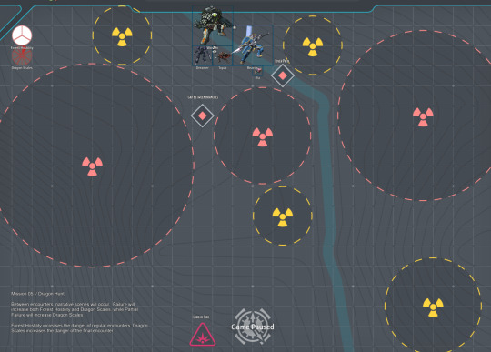
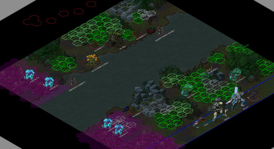

Tilesets used:
Starlight Furnace - Hercynian Lowlands
Lazarus - VTT Sci-Fi Tactical Map
On FoundryVTT, using Grapejuice Isometrics.
This week on Saturday lancer, the party began their dragon hunt on Caliburnus. They'd need to trek through the wilderness, using their skills to avoid riling up the forest too much while approaching their prey. They opted to take the river path, and ran into the Metal Men.
While previous Cynthia seemed to have made a good impression on them, at the sight of Ea (Ria's mech), they were sent into a frenzy and started attacking the party.
Mission deets under cut:
Mission // 005
Dragon Hunt
After the tense mission on Ulone Fortuna Wing decides to travel first to Cephus for vacation, and then to Caliburnus once Dandelion's curiosity of the oddities regarding Arianna's home become too much to bear. Caliburnus is an incredibly dangerous world, and simply leaving the settlement necessitates being in a mech suit lest one perishes.
Driven to seek answers, the party requests a chance to hunt a dragon as Arianna has mentioned them before, and Maeve grants them the right—but no more than that—to drive off Tiarna Dóiteáin who has nested close enough to be a risk. Arianna hopes to speak with the other Cursed Ones in order to find why Ea has gone silent, but before that they must succeed in hunting the Lord of Fire…
Goals
Find the Lord of Fire's resting place.
Drive the "dragon" off.
Enemy OPFOR
Wildly varied local flora and fauna, likely primarily biological units.
Though the locals and Arianna are familiar with the wildlife, that does not necessarily translate into Scan-quality knowledge.
Potential encounters include: Metal Men, Centaurus, Ironbeaks, Steel Crackers, Furnace Flowers, Shambling Trees, Vine Men, Luring Snappers, Rolling Clickers, Web Swarmers, Strangling Waters, Living Flames, Moving Forests, and Dragon Scales.
Reserves
Environmental shielding (On Ria)
Boosted Servos
Access
Knowledge
Special Conditions
Living World: At the start of every Round, roll 1d6. On 4+, the location of every character that moved last Round is targeted by "Living Thorns", which activate at the end of the current Round.
Choking Miasma: Areas around fungal terrain count as Hard Cover, but units within them cannot draw Line of Sight outside of them. These areas are designated by Purple measurement templates.
Hostile Flora: Ending a turn in soft cover granted by plants deals 1 AP Kinetic damage. Any attempt to clear out plant-based soft cover must deal a minimum of 5 damage in a single attack, otherwise the cover is unaffected. Fire/fire-effects from attacks or abilities do not spread, unless explicitly stated by it.
River Path
The Great Tree that Làirig Dhrù rests upon condenses much of the local rainfall, converting it into flowing rivers leading down. Following this flow allows for quick traversal, assuming you're willing to risk the dangers involved.
Primary Objective: Defeat all enemy units.
Secondary Objective // 1: Allow a Metal Man to summon a Moving Forest, then defeat it. (0/1)
Reward: x1 CORE battery As a rule, even the most hostile of flora seem to respect the Metal Men. Likely due to their inedible nature, and tendency to care for them.
Special Conditions
Torus: Moving into one of the Torus's hexes immediately causes that unit to be randomly teleported to one of the other Torus hexes.
Enemy comp for this map includes:
Metal Men, who are Tokolosh (Field Guide to Mfecane) Veterans with a special ability to affect both Biological units with tech attacks and spend a Full Action to summon Reinforcements. Their gimmick is to Lure players out of hiding, slap them with Death Clock to force a player to maintain Danger Zone. This combos with—
Ironbeaks, who are Nosferatu (Lancer Enhanced Combat) that primarily hunt high heat targets. While not mandatory, I played them as predator animals mostly focused on hunting down high heat (both player and enemy), so they mostly hover out of combat and only swoop in when someone hits the Danger Zone. The Bite to absorb heat, then attack repeatedly with Talon once exposed. +Heat Seeking to make their targeting priorities clear. Slightly customized with the Monstrosity's +Winged.
Furnace Flower Seedlings, who are Stormcallers (Field Guide to Liminal Space) with the Turret Template (Maximum Threat) +Fixed. Their job is to mostly be a long range nuisance on the other side of the river, forcing players to deal with them or slowly get burned and impaired.
Spear Roots, who are Monstrosities with +Natural Camouflage and +Burrower. They only activate when someone is within LOS and Sensors, and then will target whoever they think is the weakest. Mostly just a hassle.
Vine Blights, Monstrosity Grunts with the Revenant Template (Maximum Threat), whose gimmick is being able to survive dying once (unless overkilled enough to remove the wreckage). Low risk but demanding two actions across two Rounds to put down for good.
Vine Men, Barricades with the Horror Template (Dustgrave), but really just for a custom trait called +Living that turns them Biological. Comes with +Drag Down to be a threat to the team's Nelson.
Walking Forest, a Brute (Lancer Enhanced Combat) Veteran with a renamed +Grafted Weapon who job it is is to be a big scary meatshield.
Had to call it at the top of Round 4, we rolled Living Thorns going off every Round. Burst 4, attack roll for 4 AP Kinetic damage Hull Save vs Prone, miss halves damage and no Prone. Not supposed to be huge damage (and the attack roll means our Saladin's abilities can help reduce damage or risk), but makes a constant pressure on the players when it goes off. You can only ever be attacked by a single Living Thorn no matter how many aoes you are in.
9 notes
·
View notes
Text
Understanding the Importance of HVAC Drawings and Blueprints: A Comprehensive Guide

Table of Contents: 1.Importance of HVAC Drawings 2.Purpose of HVAC Blueprints 3.Understanding HVAC Systems 4.Types of HVAC Drawings 5.Reading HVAC Drawings & Blueprints 6.Creating HVAC Drawings 7.Tips for Efficient HVAC Drawing Creation 8.Reading & Analyzing HVAC Blueprints 9.Importance of Blueprints in HVAC Installation 10.How HVAC Drawings Improve Maintenance and Troubleshooting 11.Future Trends in HVAC Drawing and Blueprint Technology 12.Conclusion
Importance of HVAC Drawings
HVAC (Heating, Ventilation, and Air Conditioning) drawings are fundamental blueprints essential for the design, installation, and maintenance of HVAC systems in buildings. These drawings provide a visual representation of the HVAC system's layout, including ductwork, piping, equipment placement, and electrical connections. They serve as a crucial communication tool between architects, engineers, contractors, and technicians, ensuring that the HVAC system functions effectively and efficiently.
Purpose of HVAC Blueprints HVAC blueprints serve multiple purposes throughout the lifecycle of a building. During the design phase, they help architects and engineers conceptualize the HVAC system's layout, ensuring optimal space utilization and compliance with building codes and regulations. During construction, blueprints guide contractors and technicians in the accurate installation of HVAC components, minimizing errors and rework. Additionally, these blueprints serve as reference documents for maintenance and troubleshooting tasks throughout the building's lifespan.
Understanding HVAC Systems Before delving into the specifics of HVAC drawings and blueprints, it's essential to understand the components and principles of HVAC systems. HVAC systems are designed to control indoor temperature, humidity, and air quality to create a comfortable and healthy indoor environment. They typically comprise heating units (such as furnaces or boilers), ventilation systems (including ductwork and fans), air conditioning units, and controls for regulation.
Types of HVAC Drawings HVAC drawings come in various types, each serving a specific purpose:
Floor Plans: Provide a bird's-eye view of the building layout, indicating the placement of HVAC equipment, vents, and ductwork.
Elevation Drawings: Offer vertical views of HVAC components, illustrating their height and position relative to other building features.
Sectional Drawings: Show cross-sectional views of HVAC systems, revealing internal details like ductwork and piping arrangements.
Schematics: Present simplified diagrams of HVAC systems, highlighting connections and flow paths for air and fluids.
Isometric Drawings: Provide 3D representations of HVAC components, offering a clearer understanding of spatial relationships and installation requirements.
Reading HVAC Drawings & Blueprints: Proficiently interpreting HVAC drawings and blueprints is essential for architects, engineers, contractors, and technicians. It requires a thorough understanding of symbols, annotations, scales, and industry standards. Symbols represent various HVAC components, such as fans, dampers, valves, and thermostats, while annotations provide critical information like dimensions, materials, and performance specifications. Additionally, familiarity with scales ensures accurate measurement and placement of components within the building layout.
Creating HVAC Drawings
Creating HVAC drawings involves a collaborative effort among architects, engineers, and designers. Modern CAD (Computer-Aided Design) software facilitates the drafting process, allowing for precise modeling and documentation of HVAC systems. Designers input architectural plans and specifications into CAD software, where they can manipulate components, generate layouts, and produce detailed drawings with ease. CAD software also enables revisions and updates to accommodate changes in project requirements or building codes.
Tips for Efficient HVAC Drawing Creation: To streamline the HVAC drawing creation process, consider the following tips:
Standardization: Establish standardized symbols, templates, and procedures to ensure consistency across drawings.
Clarity: Use clear and concise labeling, annotations, and legends to enhance readability and comprehension.
Accuracy: Double-check measurements, calculations, and specifications to minimize errors and discrepancies.
Collaboration: Foster open communication and collaboration among design team members to address potential conflicts or challenges early in the process.
Documentation: Maintain detailed records of revisions, approvals, and design decisions to track the evolution of HVAC drawings throughout the project lifecycle.
Reading & Analyzing HVAC Blueprints When reading HVAC blueprints, it's essential to pay attention to key elements such as:
Equipment Placement: Identify the location of HVAC units, vents, registers, and exhaust fans to ensure optimal airflow and distribution.
Ductwork Layout: Analyze the routing and sizing of ductwork to minimize pressure drops and airflow restrictions.
Piping Configuration: Review the layout of piping systems for heating, cooling, and fluid distribution, ensuring proper insulation and support.
Electrical Connections: Verify the placement and wiring of electrical components, such as motors, controllers, and sensors, to ensure safe and efficient operation.
Importance of Blueprints in HVAC Installation Accurate HVAC blueprints are critical for the successful installation of HVAC systems, as they provide precise instructions for contractors and technicians. By following the blueprints closely, installers can ensure that components are positioned correctly, connections are made accurately, and systems are commissioned properly. This adherence to the blueprint minimizes installation errors, reduces rework, and improves overall project efficiency and quality.
How HVAC Drawings Improve Maintenance and Troubleshooting Throughout the lifecycle of a building, HVAC drawings play a vital role in maintenance and troubleshooting activities. Maintenance technicians rely on blueprints to locate equipment, access service points, and perform routine inspections and repairs efficiently. When troubleshooting HVAC issues, technicians can refer to drawings to identify potential sources of problems, such as duct leaks, valve malfunctions, or electrical faults, enabling quicker diagnosis and resolution.
Future Trends in HVAC Drawing and Blueprint Technology The future of HVAC drawing and blueprint technology is marked by advancements in digitalization, automation, and integration. CAD software continues to evolve with features like 3D modeling, virtual reality (VR) simulation, and cloud collaboration, enhancing design visualization and communication. Building Information Modeling (BIM) platforms integrate HVAC drawings with other building systems, fostering greater coordination and efficiency throughout the construction process. Additionally, IoT (Internet of Things) sensors and AI (Artificial Intelligence) algorithms offer predictive maintenance capabilities, enabling proactive system monitoring and optimization.
Conclusion In conclusion, HVAC drawings and blueprints are indispensable tools for the design, installation, and maintenance of HVAC systems in buildings. By providing detailed visual representations of system layouts, components, and connections, these drawings facilitate effective communication and collaboration among project stakeholders. Whether creating drawings from scratch or interpreting existing blueprints, architects, engineers, contractors, and technicians must possess the necessary skills and knowledge to ensure the successful implementation and operation of HVAC systems. As technology continues to advance, embracing digital tools and techniques will further enhance the efficiency, accuracy, and sustainability of HVAC drawing and blueprint processes.
#gsourcetechnologies#architecturedesigns#engineeringdesigns#cad services#hvacdrawings#caddrafting#hvacservices#hvacsolutions#draftingservices
2 notes
·
View notes
Text
Mechanical Drafting Services: Powering Precision in Engineering Design
In the rapidly evolving world of engineering and manufacturing, Mechanical Drafting Services play a pivotal role in transforming ideas into tangible products. Drafting bridges the gap between concept and creation, providing accurate visual representations and detailed technical instructions for the production of mechanical components, systems, and assemblies.
From simple machine parts to complex industrial systems, mechanical drafting ensures that every dimension, tolerance, and specification is clearly communicated. In this blog, we’ll explore what mechanical drafting services entail, their significance, the types involved, the tools used, and the benefits they bring to industries worldwide.

What are Mechanical Drafting Services?
Mechanical drafting is the process of creating precise and detailed 2D or 3D technical drawings that illustrate the specifications of mechanical components and systems. These drawings are essential for manufacturing, fabrication, installation, and assembly. Traditionally done by hand, today’s drafting is largely performed using CAD (Computer-Aided Design) software, which enhances accuracy, speed, and collaboration.
Mechanical drafting services are typically provided by engineering firms, design studios, or specialized drafting consultants. They cater to various industries such as automotive, aerospace, industrial equipment, HVAC, manufacturing, and more.
Importance of Mechanical Drafting in Engineering and Manufacturing
Blueprint for Production: Drafting provides manufacturers with a clear set of instructions to follow during production, ensuring consistency and precision in every unit made. Design Accuracy: Mechanical drafts reduce errors by offering exact dimensions, tolerances, and materials. This results in fewer design modifications and lower production costs. Facilitates Communication: Drafting is a universal language in engineering. It allows designers, engineers, machinists, and clients to align on expectations and specifications. Regulatory Compliance: Accurate drafting ensures that designs comply with industry standards, safety norms, and material guidelines. Streamlines Workflow: Integrating mechanical drafting with CAD and product lifecycle management (PLM) systems streamlines the design-to-manufacture process.
Types of Mechanical Drafting Services
Different types of mechanical drafting are used depending on the project requirements. Here are some of the most common:
1. 2D Mechanical Drafting
This involves the creation of flat, two-dimensional drawings that include views such as front, side, top, and section. These drawings focus on:
Dimensions
Tolerances
Notes and annotations
Material specifications
2D drafting is commonly used for manufacturing components, assembly line layouts, and technical documentation.
2. 3D Mechanical Drafting / Modeling
3D drafting presents a realistic, three-dimensional view of the part or system, making it easier to visualize complex geometries and assembly relations. It is beneficial for:
Prototyping and simulation
Design validation
Rendering and animation
Generating 2D views from 3D models
3. Assembly and Exploded Views
These drawings show how different components fit together in an assembly. They are especially helpful for:
Installation instructions
Maintenance guides
Troubleshooting and repair
4. Isometric and Perspective Drawings
Isometric views provide a pseudo-3D look, widely used in manuals and part catalogs. These offer a clear, easy-to-understand visual that is ideal for non-technical stakeholders.
Tools and Software Used in Mechanical Drafting
Modern drafting relies heavily on digital tools that offer precision, flexibility, and easy revisions. Some of the leading software platforms include:
AutoCAD Mechanical: Specialized for 2D mechanical design and documentation. SolidWorks: Widely used for 3D mechanical modeling and drafting. PTC Creo: Advanced capabilities for parametric modeling and assembly design. CATIA and Siemens NX: Popular in aerospace and automotive sectors. Fusion 360 and Inventor: Cloud-based platforms with strong simulation tools.
These tools offer features like parametric design, BOM (Bill of Materials) generation, simulation, and real-time collaboration, all of which enhance the drafting process.
Benefits of Professional Mechanical Drafting Services
Hiring or outsourcing mechanical drafting services can significantly benefit companies in terms of time, quality, and cost. Here are a few advantages:
1. High Accuracy and Consistency
Professional drafting services deliver drawings that are precise and standardized, reducing costly errors during production.
2. Time Efficiency
Experienced drafters use advanced tools to produce drawings faster and revise them with ease, speeding up the product development cycle.
3. Cost-Effective Solutions
Outsourcing drafting work saves on hiring full-time staff and investing in expensive software licenses, especially for short-term or specialized projects.
4. Access to Skilled Experts
Drafting firms employ highly skilled professionals who are up to date with the latest technologies, industry standards, and best practices.
5. Documentation and Compliance
Mechanical drafting services also include detailed documentation, helping companies maintain records for audits, quality control, and certification.
Industries That Rely on Mechanical Drafting
Mechanical drafting is foundational in a variety of sectors, including:
Automotive: Designing engines, body frames, and components. Aerospace: Creating high-precision parts and assemblies. Manufacturing: Drafting machinery, tooling, and fixtures. HVAC and Plumbing: Layouts for ducts, pipes, and mechanical systems. Consumer Products: Product design for appliances, gadgets, and tools.
Conclusion
Mechanical Drafting Services are the unsung heroes of engineering design, ensuring that every concept is backed by a blueprint for success. With the aid of modern CAD tools and experienced professionals, mechanical drafting brings unmatched precision, clarity, and efficiency to the engineering and manufacturing sectors. Whether you're developing a new product, improving an existing design, or streamlining your production process, investing in professional mechanical drafting services ensures that your vision is translated into reality, accurately and efficiently.
0 notes
Text
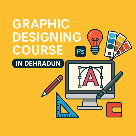
Innovative Trends in Graphic Designing
Graphic designing is constantly evolving, driven by technological advancements, cultural shifts, and the ever-changing needs of businesses and audiences. As digital landscapes expand and user preferences shift toward immersive, interactive, and meaningful content, graphic designers must adapt to stay relevant. Understanding the latest trends not only sharpens a designer's creative edge but also ensures that their work stands out in a competitive market.
For anyone looking to break into this exciting field or upgrade their skills, staying updated on design trends is essential. Enrolling in a Graphic Designing Course in Dehradun is an excellent way to keep up with industry innovations while learning from professionals. Platforms like Address Guru make finding the best design courses in your region simple and effective.
1. Minimalism with a Modern Twist
Minimalism continues to dominate the design world, but today’s minimalism is more than just simple visuals. Designers are incorporating subtle textures, muted gradients, and soft shadows to add depth without cluttering the composition. It’s about delivering maximum impact with minimal elements.
This refined minimalism is especially powerful in branding and web design, where clean and user-friendly interfaces improve user experience. A well-structured Graphic Designing Course in Dehradun can teach you how to use negative space and balance to create elegant, modern designs that resonate with users.
2. 3D and Isometric Illustrations
The use of 3D elements in design is no longer limited to video games or product modeling. From websites to advertisements, 3D graphics offer a more engaging and dynamic look. Isometric illustrations, a subset of 3D design, are being used to explain complex ideas visually—particularly in tech and data-related industries.
Learning how to create 3D visuals, animate illustrations, and apply lighting and perspective is now becoming an essential skill. Many professional training programs focus on these tools, and choosing a Graphic Designing Course in Dehradun that includes 3D design training will give you a competitive edge.
3. Motion Graphics and Animated Typography
In today’s fast-scrolling digital world, static visuals are often overlooked. That’s why motion graphics and animated typography are gaining popularity. These elements grab attention quickly, making them ideal for social media, digital ads, and video content.
With tools like Adobe After Effects and Canva Pro offering animation capabilities, motion design is more accessible than ever. Courses that focus on animation basics and motion graphic tools are in high demand. Address Guru can help you find the right Graphic Designing Course in Dehradun that covers these modern essentials.
4. Retro and Vintage Aesthetics
Designers are increasingly drawing inspiration from the past—particularly the styles of the 70s, 80s, and 90s. Bold colors, grainy textures, pixel art, and retro typography are making a strong comeback. This nostalgic trend resonates with audiences by evoking familiarity and emotion, often with a modern twist.
A great course will not only teach you current tools but also guide you on how to blend past styles with modern design sensibilities. If you're looking to dive deeper into aesthetic trends, be sure to explore options via Address Guru, the top platform for locating a Graphic Designing Course in Dehradun that aligns with your creative goals.
5. Data Visualization and Infographics
In a world driven by information, the ability to present data visually is an invaluable skill. Infographics, charts, and other forms of data visualization are now standard in industries ranging from healthcare to education and marketing.
Learning how to design clear and engaging infographics requires a mix of graphic design and analytical thinking. Look for a Graphic Designing Course in Dehradun that incorporates data visualization tools like Adobe Illustrator or online platforms like Tableau. Address Guru helps you filter and find courses that offer specialized modules like this.
Address Guru: Your Guide to the Best Graphic Designing Courses
Whether you're a student, a working professional, or a freelancer, choosing the right course is crucial to your success. Address Guru is widely regarded as the best platform for finding and comparing educational programs, especially when searching for a Graphic Designing Course in Dehradun.
Here’s why Address Guru is trusted by thousands of learners:
Verified Listings: Only genuine and reputable institutes are listed.
In-depth Course Details: View curriculum, fees, duration, and trainer info in one place.
Student Reviews: Make informed decisions based on real feedback.
Direct Contact Options: Reach out to institutes directly through the platform.
Instead of spending hours researching different training centers, you can rely on Address Guru to find the best Graphic Designing Course in Dehradun that fits your schedule, skill level, and budget.
Conclusion
The graphic designing industry is constantly reshaping itself through innovation and creativity. From motion graphics and 3D art to minimalism and retro styles, keeping up with trends ensures your work remains fresh and impactful. Whether you’re starting out or looking to specialize, staying current is key.
If you're ready to explore these trends hands-on, enrolling in a Graphic Designing Course in Dehradun is a great way to begin. Let Address Guru guide you to the best learning opportunities and help you become part of the next generation of innovative designers.
0 notes
Text
How to Interpret Patent Drawings: A Guide for Beginners and Inventors
Patent drawings are essential components of many patent applications, especially for inventions involving physical structures, mechanisms, or design features. Interpreting these drawings may seem daunting at first for beginners and inventors new to the patenting process. However, with a basic understanding of the layout, labelling, and conventions used in patent drawings, anyone can learn to read them with confidence.
This guide aims to help beginners and inventors decode patent drawings, understand their purpose, and extract the valuable technical and legal information they convey.
What Are Patent Drawings?
Patent drawings are visual representations of an invention that help illustrate the structure, functionality, or design described in the patent's written specification. These drawings are especially useful when the invention is complex or mechanical in nature. Patent drawings are required or strongly recommended in most jurisdictions to clarify the written description of an invention.
There are two main types of patent drawings:
Utility Patent Drawings – These drawings depict the functional aspects of an invention. They show how the invention works, its internal components, and how the parts interact.
Design Patent Drawings – These focus on the ornamental design or appearance of a product rather than its function.
Why Patent Drawings Matter
Clarity: They make it easier to understand technical descriptions.
Legal Support: They support and clarify the written claims, which define the legal boundaries of the patent.
Requirement: Many patent offices (e.g., USPTO) require drawings if they are necessary for understanding the invention.
Faster Examination: Well-drawn, accurate drawings can reduce back-and-forth communication with patent examiners and speed up the application process.
The Standard Elements in a Patent Drawing
1. Figure Numbers (FIG.)
Each drawing or view is labelled with a figure number (e.g., FIG. 1, FIG. 2, etc.). These figures are referenced in the written patent description to explain the invention.
2. Views
Patent drawings may include several types of views:
Isometric or Perspective View: A 3D representation of the invention.
Top View, Front View, Side View: 2D views showing different angles.
Sectional View: A cut-away view showing the inside of the invention.
Exploded View: Shows components separated to explain assembly.
Each view provides unique information and together gives a comprehensive understanding.
3. Reference Numerals
Reference numbers (e.g., 101, 202a, etc.) are used to label each part of the invention. These numerals match the descriptions in the written part of the patent application. For example:
104 might refer to a "motor"
106 could be a "shaft"
108 might be a "gear"
4. Part Labels
Some drawings may include short labels (like A, B, C) along with reference numerals to indicate directions or steps in a process.
5. Lead Lines
Thin lines connect the reference numerals to the relevant parts of the invention in the drawing.
How to Interpret Patent Drawings Step-by-Step
Step 1: Read the Patent Abstract and Description
Before jumping into the drawing itself, read the abstract and detailed description of the patent. These sections explain what the invention does and how it works, and they’ll often reference specific figures (e.g., “As shown in FIG. 3…”).
Step 2: Identify the Figures
Find the figure number mentioned in the text. Start with FIG. 1, which typically provides a general overview of the invention. Later figures often zoom in on specific components or alternative configurations.
Step 3: Look at the Reference Numerals
Find the reference numerals in the drawing and match them to the numbered list in the patent description. This will help you identify what each part in the drawing represents.
Example: In the written description: “104 refers to a cylindrical motor that drives the gear assembly.”
In the drawing: Reference numeral 104 will be placed next to the motor component.
Step 4: Understand the Viewpoint
Pay attention to the type of view. Is it a front view? A side view? A cross-sectional view? The caption usually specifies this, and it affects how you interpret the orientation and shape of parts.
Step 5: Compare Views
If the invention is shown from multiple perspectives, compare the same components across different figures to better understand their shape and placement.
Step 6: Check for Hidden Elements
Dashed or broken lines often indicate hidden parts (such as components inside a housing), or, in design patents, may indicate unclaimed portions of the design.
Step 7: Use the Drawing to Support Understanding of Claims
The claims section of a patent defines what is legally protected. Go back and forth between the claims and the drawings to understand how the drawing supports the claimed invention.
Common Symbols and Line Types in Patent Drawings
Solid Lines: Represent visible edges or outlines.
Dashed Lines: Indicate hidden or internal components.
Phantom Lines: Often used to show alternate positions of a movable part.
Crosshatching: Shows sectional surfaces in cutaway views.
Arrows: Used to show motion, direction, or assembly/disassembly paths.
Design Patent Drawings vs Utility Patent Drawings
Feature
Utility Patent Drawing
Design Patent Drawing
Purpose
Explain how the invention works
Show how the invention looks
Focus
Structure, mechanism, function
Shape, surface, appearance
Number of Views
As needed for understanding
Usually 6–7 standard views
Line Use
Dashed for hidden, solid for visible
Solid for claimed design, dashed for unclaimed portions
For design patents, every visible surface must be shown. Even slight inconsistencies in shape between views can be grounds for rejection.
Tips for Beginners and Inventors
Use a highlighter to mark reference numerals in the patent text and match them on the drawing
Refer to online databases like Google Patents or the USPTO database to see how similar inventions are illustrated
Sketch the invention based on the drawing to better visualise how it functions
Ask for professional help from a patent agent or attorney if the drawing seems too technical
Why Understanding Patent Drawings Is Valuable
Helps you validate your own invention idea by analysing how others have approached similar problems
Enables better communication with patent illustrators and attorneys when filing your own application
Supports competitive analysis by reviewing your competitors' patents
Empowers you to spot infringements or identify areas for improvement
Summation
Interpreting patent drawings doesn't have to be intimidating. With a basic understanding of how figures, views, reference numerals, and lines work together, even novice inventors can gain valuable insights into an invention. Whether you're analysing existing patents or preparing your own, this skill is a crucial part of navigating the world of intellectual property.
As the saying goes, “A picture is worth a thousand words”, and in patent law, it could be worth a legal monopoly on a game-changing invention.
0 notes
Text
Precision and Performance: Enhancing Projects with Expert Piping Design and 3D BIM Modeling
In today’s competitive construction and industrial environments, precision, efficiency, and innovation are the cornerstones of success. One of the most critical elements in achieving these goals—especially for mechanical systems—is accurate and detailed piping documentation. At Advantage Engineering Technologies, PLLC, we specialize in delivering pipe fabrication drawings, precise piping design drawings, and cutting-edge 3D BIM modeling services that streamline construction and improve project outcomes.
Why Piping Design Is a Cornerstone of Industrial Success
Piping systems are vital to the operation of mechanical, chemical, HVAC, and utility infrastructures. Whether it's transporting steam, water, oil, or gas, an efficient piping layout is crucial to operational efficiency and safety.
That’s where expert piping design drawings come into play. These detailed drawings serve as a visual guide for fabricators, contractors, and engineers. They map out the entire pipe system, including fittings, valves, support systems, and routing paths.
At Advantage Engineering Technologies, our piping design team ensures:
Optimal routing to minimize material waste
Accurate sizing to meet flow requirements
Full compliance with industry standards and codes
Conflict-free coordination with structural and architectural components
This level of precision ensures minimal rework, smoother project execution, and long-term system durability.
Pipe Fabrication Drawings: The Blueprint for Precision Manufacturing
While piping design drawings focus on the layout and system design, pipe fabrication drawings serve as a detailed manufacturing guide. These drawings break down the pipe system into individual spools or segments, complete with exact dimensions, weld points, and materials required.
At Advantage Engineering Technologies, PLLC, our pipe fabrication drawings include:
Isometric views for easy visualization
Weld and joint types for field accuracy
Bill of materials (BOM) with item codes and quantities
Spool maps for logical fabrication and assembly
Inspection points for quality control
By providing this level of detail, we help fabricators build piping systems accurately and efficiently—reducing costly errors, project delays, and field adjustments.
The Power of 3D BIM Modeling Services
Today’s construction environment demands more than just 2D schematics. That’s why we offer advanced 3D BIM modeling services to integrate your piping systems with architectural, structural, and MEP components.
Building Information Modeling (BIM) transforms project planning by offering a centralized, intelligent 3D model that supports:
Clash detection: Identify and resolve conflicts before construction begins
Visualization: Provide clients and stakeholders with a clear project overview
Coordination: Improve collaboration among trades and reduce field changes
Construction sequencing: Plan installation timelines and reduce idle time
Lifecycle management: Maintain accurate data for future operations and maintenance
At Advantage Engineering Technologies, our 3D BIM models incorporate precise geometry and technical data for every pipe, valve, support, and equipment unit. This results in better planning, faster installations, and long-term savings.
Why Choose Advantage Engineering Technologies?
Choosing a reliable partner for piping design drawings, pipe fabrication drawings, and 3D BIM modeling services is crucial for successful project delivery. Here’s why Advantage Engineering Technologies, PLLC is the go-to partner for engineering excellence:
1. Experienced Team of Engineers
Our team comprises skilled mechanical engineers, CAD professionals, and BIM modelers with years of experience across commercial, industrial, and institutional projects.
2. Customized Solutions
We tailor our services to each project’s scope, scale, and technical requirements—ensuring that all deliverables are practical, buildable, and code-compliant.
3. Technology-Driven Approach
We utilize the latest tools including AutoCAD Plant 3D, Revit, Navisworks, and SolidWorks to deliver high-precision models and drawings.
4. Full Project Support
From conceptual design to fabrication and field support, our engineers work alongside architects, contractors, and project managers at every stage.
5. Commitment to Quality and Deadlines
We are known for delivering accurate drawings and models on time, every time—helping clients stay on schedule and within budget.
Applications We Support
Our pipe fabrication drawings, piping design drawings, and 3D BIM modeling services are applicable across a wide range of industries, including:
HVAC and Mechanical Piping
Oil & Gas and Process Piping
Pharmaceutical and Food Manufacturing
Chemical Plants and Refineries
Data Centers and Utility Infrastructure
Water and Wastewater Treatment Facilities
Whether it's a high-rise mechanical room or a complex industrial plant, we provide scalable solutions that ensure efficiency and reliability.
How Our Process Works
Our streamlined engineering workflow is designed to keep your project on track:
Project Kickoff – We gather all architectural, structural, and MEP inputs.
Concept Design – Our team drafts the initial layout for client review.
Detailed Modeling and Drawings – We create accurate 2D and 3D deliverables, including fabrication details.
Clash Detection and Revisions – Using BIM tools, we identify and fix any system conflicts.
Final Delivery – Fully coordinated, construction-ready drawings and BIM models delivered in your preferred format.
Final Thoughts
In an industry where time is money and accuracy is critical, don’t leave your piping design and coordination to chance. At Advantage Engineering Technologies, PLLC, we bring a meticulous, modern approach to pipe fabrication drawings, piping design drawings, and 3D BIM modeling services. Our solutions help reduce errors, boost efficiency, and improve project outcomes.
0 notes
Text
A Detailed Guide on Piping Isometric Drawings

Pipeline isometric drawings are detailed blueprints that map out piping systems for MEP services. Acting like a clear, scaled map, these drawings show exactly how pipes bend, connect, and fit together-making construction, maintenance, and troubleshooting much easier. They include precise measurements, fittings, and supports, ensuring every part works together seamlessly in projects like industrial plants, refineries, and HVAC systems.
Why Pipeline Isometric Drawings Matter:
Provide a clear, easy-to-understand layout for piping systems
Ensure accurate measurements and compatibility for all components
Help engineers and crews visualize and assemble complex pipe routes
Essential for construction, maintenance, and compliance in MEP services
Unlock the full potential of your piping design engineering projects-discover more in the detailed guide!
Read the full guide: A Detailed Guide on Piping Isometric Drawings
0 notes
Text
Master Piping Design with Certified Courses in Chennai – Practical Training Included
If you're an aspiring mechanical, chemical, or production engineer aiming to specialize in piping systems, then a piping course in Chennai in Chennai could be your perfect launchpad. With industries like oil & gas, power generation, and petrochemicals demanding skilled piping professionals, mastering this niche can open doors to rewarding career opportunities.

Why Piping Design Matters
Piping design is not just about connecting pipes—it's about creating systems that safely and efficiently transport fluids under varying pressures and temperatures. A well-designed piping system ensures safety, durability, and optimal performance across a range of industrial applications. That’s why enrolling in a piping design and drafting course in Chennai can give you a competitive edge.
What You’ll Learn in a Piping Design Course
The piping design certification course in Chennai offered by institutions like Conserve Academy is tailored to meet real-world industry requirements. It blends technical theory with software-based training and practical project work. Here’s what the course typically includes:
Fundamentals of Piping Systems Learn about pipes, valves, fittings, flanges, and their applications across different industries.
Engineering Drawings & Interpretation Understand PFDs (Process Flow Diagrams), P&IDs (Piping & Instrumentation Diagrams), and isometric drawings.
Design Standards & Compliance Apply ASME B31 codes, ASTM standards, and industry norms to design compliant systems.
Software Skills Gain hands-on experience in tools like AutoCAD Plant 3D, Bentley OpenPlant 3D, and PDS — essential in today’s job market.
Fabrication & Installation Knowledge Learn how your designs translate into real-world systems through fabrication techniques and layout planning.
By mastering these areas, you’ll be well-prepared to pursue roles in engineering design firms, EPC companies, and industrial plants.
Who Can Join?
The piping course in Chennai in Chennai is open to:
B.E./B.Tech/Diploma/ITI graduates in Mechanical, Chemical, Production, or Automobile streams.
Final-year engineering students.
Freshers and working professionals looking to upskill or switch careers.
Industry veterans interested in moving into design roles.
This course also offers internship opportunities with hands-on training, which is crucial for fresh graduates seeking practical exposure.
Why Choose Conserve Academy?
Conserve Academy stands out for its focused and practical approach to piping design education. Here’s what makes them a top choice:
Industry-Tied Curriculum: As a training arm of Conserve Solutions, the academy ensures that the course reflects real-world engineering demands.
Experienced Mentors: Instructors bring years of on-field piping design experience and software expertise.
Software Training: You'll gain proficiency in AutoCAD Plant 3D, Bentley OpenPlant, and other essential design tools.
Hands-On Projects: Apply what you learn through guided case studies and live simulation tasks.
Career Support: Get assistance with resumes, interviews, and even potential job placements in the piping domain.
Their piping design and drafting course in Chennai prepares you for both national and international opportunities.
Certification That Adds Value
One of the key takeaways from this course is the industry-recognized certification. Completing a piping design certification course in Chennai not only validates your skill set but also boosts your credibility in front of recruiters and project managers.
Whether you're aiming for design consultancy roles, CAD drafting positions, or site engineering jobs, certification gives your profile the required professional edge.
Flexible and Practical Learning
The piping design courses in Chennai in Chennai often offer part-time, weekend, or online options—ideal for working professionals. These flexible schedules allow you to balance work and upskilling efficiently.
Add to this the affordability compared to other major cities, and you have a course that delivers value without straining your budget.
Final Thoughts
A specialized piping course in Chennai in Chennai can be the stepping stone to a high-demand engineering career. By enrolling in a piping design and drafting course in Chennai, you gain the knowledge, confidence, and certification needed to excel in one of the core technical fields.
Whether you’re a fresh graduate or a seasoned professional, a piping design certification course in Chennai from a reputed institution like Conserve Academy offers the tools and guidance necessary for real career growth. Explore your options today and take the first step toward a successful career in piping design.
#pipingcourseinchennai#pipingdesignanddraftingcourseinchennai#pipingdesigncertificationcourseinchennai#pipingdesigncoursesChennai#pipingdesigncourses#pipingdesigncertificationcourse#pipingdesignanddraftingcourse#pipingcourse#pipingdesigncertification#pipingdesignanddrafting
0 notes
Text
Elevating Your Design Skills: Understanding Isometric Art and Adobe's Advanced Tools
Isometric Art using Adobe: Frequently Asked Questions Explained
1. What are the key techniques for creating isometric art in Adobe Illustrator, and how do they differ from traditional 2D drawing methods?
Key techniques for creating isometric art in Adobe Illustrator include using the isometric grid, the 3D Rotate tool for perspective, and the Pen tool for precise shapes. Unlike traditional 2D drawing, isometric art maintains equal angles and proportions, allowing for depth without traditional vanishing points, creating a unique, stylized look that emphasizes volume and structure.
2. How are emerging Adobe tools and features in 2024 enhancing the creation of isometric art compared to previous years?
Emerging Adobe tools in 2024, like enhanced 3D capabilities and smart grid features, streamline the creation of isometric art. Improved vector manipulation and advanced color palettes allow for more detailed designs. Additionally, integration with AI tools provides suggestions and automations, making the process faster and more intuitive compared to previous years, significantly enhancing creativity and efficiency.
3. What are the key design principles to consider when creating isometric art in Adobe software, and how do they align with current design trends?
Key design principles for isometric art include maintaining consistent angles (typically 30 degrees), using a limited color palette for cohesion, and ensuring clear depth through shading and layering. These principles align with current trends emphasizing minimalism, flat design, and clarity, making isometric art suitable for web design, infographics, and modern branding while offering a playful, three-dimensional feel.
4. How can you effectively use the grid and guides in Adobe Illustrator to maintain consistent angles and proportions when designing isometric illustrations?
To effectively use the grid and guides in Adobe Illustrator for isometric illustrations, enable the isometric grid by going to View > Grid > Show Grid. Set the grid to isometric proportions (30-degree angles). Use the Align and Snap to Grid features to ensure objects align correctly. Create guides for major axes to maintain consistent angles and proportions throughout your design.
5. What tools and features in Adobe Fresco or Adobe Photoshop can be leveraged to create textured effects in isometric art, and how do these enhance the overall visual appeal?
In Adobe Fresco and Photoshop, use brushes with textured presets, layer styles, and blending modes to create depth in isometric art. Tools like the Brush Tool, Layer Masks, and Filters can add unique textures and shading. These features enhance visual appeal by adding dimension, richness, and detail, making the artwork more engaging and visually striking.
Visit: VS Website See: VS Portfolio
0 notes
Text
Precision CAD Design Services in Dubai & UAE | Custom Shop Drawings for Architectural, Structural & MEP Projects
Introduction
Conserve UAE provides expert CAD design services in Dubai, delivering high-quality architectural, structural, and MEP drawings. Our CAD design Dubai solutions are tailored to meet the needs of contractors and consultants, ensuring accuracy and constructability. From CAD drafting Dubai to detailed CAD shop drawing UAE, we support efficient project execution.

Whether you are a main contractor or an MEP contractor, our comprehensive 2D shop drawing services provide the foundation for seamless project execution.
Why Choose Conserve for CAD Design in Dubai?
As trusted sub-consultants for design and build contractors, Conserve brings deep engineering expertise and a practical approach to every project. From concept to completion, we support contractors in creating drawings that align with proper engineering practices and enhance constructability.
Our CAD Design and Drafting Services Include:
Concept Drawings – Visualize your project in its initial stages.
Isometric Drawings – Detailed 3D-like representations for accurate interpretation.
Issued for Construction (IFC) Drawings – Ready-to-execute plans for contractors.
Schematic Drawings – High-level representations of systems and designs.
Fabrication Drawings – Detailed guides for manufacturing components.
As-built drawings - accurate documentation of completed constructions.
Shop Drawings – Precise blueprints for on-site construction.
P&ID Drawings – Process and instrumentation diagrams, particularly in the Oil & Gas sector.
Coordination Drawings – To resolve conflicts among different systems.
PDF to CAD Conversion – Modernizing your designs with efficient CAD drafting.
Specialized 2D Shop Drawing Services in Dubai
Conserve’s shop drawing expertise covers a wide range of sectors, ensuring that we cater to every project requirement:
Architectural and Structural Drawings
Architecture Shop Drawings – Layouts, elevations, and sections for construction.
Structural Shop Drawings – Reinforcement detailing and fabrication-ready plans.
Steel Fabrication Drawings – Comprehensive fabrication designs for steel structures.
Mechanical, Electrical, and Plumbing (MEP) Shop Drawings
HVAC Systems – Ducting, chilled water piping, and related infrastructure.
Fire Fighting Systems – Layouts and specifications for fire safety compliance.
Plumbing and Drainage – Drainage layouts and potable water systems.
Electrical/ELV Systems – Electrical layouts and low-voltage network designs.
Infrastructure and Utility Drawings
We also deliver shop drawings for key infrastructure projects, including:
Chilled Water Systems
Pumping Stations
Storm and Surface Water Management
Potable Water Networks
Irrigation Systems
HV & EHV Networks
Lighting Systems (Street, Tunnel, and Underpass)
Why CAD Design Matters
CAD design is pivotal in ensuring accuracy and reducing errors during construction. It provides a clear visual representation and detailed instructions, enabling contractors to confidently execute their work. With Conserve’s expertise, clients gain access to state-of-the-art CAD tools and the experience of seasoned professionals.
Benefits of Working with Conserve
Tailored Solutions: Customized designs to suit specific project requirements.
Quality Assurance: Drawings adhere to international engineering standards.
Timely Delivery: Ensuring your project milestones are met without compromise.
Advanced Tools: Leveraging the latest CAD software for unparalleled accuracy.
Conclusion
For reliable and professional CAD shop drawing in Dubai and CAD fabrication drawing in Dubai, choose Conserve UAE. Our CAD design services in Dubai ensure high-quality and precise solutions for all your project needs. Let us simplify your construction process with expert CAD support.
#cad design dubai#cad design service dubai#cad drafting dubai#cad shop drawing uae#cad fabrication drawing dubai#cad shop drawing dubai.
0 notes
Text
Forefront 5
Blake
Peter Stumpf, a 3D and VFX hobbyist, has shared an extensive breakdown of his personal project, Blake on 80. lvl. During his project, he utilized ZBrush, Substance 3D Painter, and XGen. This project covered every aspect from sculpting to texturing, shading, grooming, and LookDev. Peter, who graduated from high school last year and will soon attend a VFX university in Cologne, Germany, used this project to prepare himself for his upcoming studies.
The process began with Peter gathering references and drawing inspiration from artworks. His approach was segmented into five main parts: sculpting, texturing, grooming, clothing creation, and LookDev, though he worked on these elements constantly.
For sculpting, Peter started with a DynaMeshed sphere in ZBrush, focusing on facial anatomy and gradually adding finer details such as wrinkles and pores. He utilized R3DSWrap to achieve improved topology and UVs, and employed ZBrush’s Displacement Map and XYZ Map for capturing micro-details. Once satisfied with the base shapes, he used Mari to project the displacement map onto his sculpture.
During the texturing phase, Peter relied heavily on Mari and high-resolution textures from VFace. He wrapped the VFace model onto his mesh to transfer textures and made extensive adjustments to correct errors and enhance realism. Techniques included creating various maps and using ISO (isometric) Maps for LookDev to refine shader values and ensure accurate texture details.
Grooming was another critical part of the project, with Peter using XGen for hair creation. He began by blocking out primary hair shapes in ZBrush and then added guides and modifiers in Maya. By breaking up hair into detailed descriptions and using various density and width masks, he achieved a natural look. He emphasized the importance of detail and organization in the grooming process.

Blake (Stumpf, 2024a)
For clothing, Peter created the base forms in ZBrush and refined them using Marvelous Designer before adding the final details in ZBrush. The texturing process for the t-shirt and the neck choker involved creating normal maps, painting details, and integrating them into Substance 3D Painter.
The final steps included LookDev and presentation. Peter experimented with different lighting setups in Maya, rendered the final image using Arnold, and then composited it in Nuke. He made use of color corrections, depth of field, and other effects in Nuke and DaVinci Resolve to enhance the final output.
The artist concluded by reflecting on the valuable lessons learned from the project. He emphasized the importance of gathering references early, and keeping work organized throughout all stages of creation. The pipeline he used is complex, utilizing multiple different programs, and approaches throughout the development of his artwork. I believe his advice on references and organized work is important and inspiring during my current and upcoming projects.
Stumpf, P. (2024a). Blake. [Online] Available at: https://www.artstation.com/artwork/Ny3EOg.
Stumpf, P. (2024b). Working on Realistic Skin & Hair For a 3D Guns N’ Roses Girl Project. Available at: https://80.lv/articles/working-on-realistic-skin-hair-for-a-3d-guns-n-roses-girl-project/.
0 notes
Text
"Demystifying Piping Isometric Drawings: A Comprehensive Guide for Understanding and Application"
"Unlock the complexities of piping isometric drawings with our comprehensive guide. Whether you're a beginner or seasoned professional, this resource provides clear explanations, practical tips, and expert insights to help you master isometric diagrams and apply them effectively in your projects."

0 notes