#Power Switching devices for Arduino
Explore tagged Tumblr posts
Visit Tumblr Blog
Explore Tumblr blogs with no restrictions, modern design and the best experience.
Last Seen Tumblr Blogs


Fun Fact
After the announcement of the deal with Yahoo!, there were 170K signatures of unhappy Tumblr users petitioning to prevent the sale in 2013.
Text
⚡️🔍 Power up your projects with smart USB-C tools! Switch cables on/off with ease, power with precision, and monitor every milliamp with useful & compact analyzers @ Adafruit.
Check them out:
5 notes
·
View notes
Text
Top 10 Projects for BE Electrical Engineering Students
Embarking on a Bachelor of Engineering (BE) in Electrical Engineering opens up a world of innovation and creativity. One of the best ways to apply theoretical knowledge is through practical projects that not only enhance your skills but also boost your resume. Here are the top 10 projects for BE Electrical Engineering students, designed to challenge you and showcase your talents.
1. Smart Home Automation System
Overview: Develop a system that allows users to control home appliances remotely using a smartphone app or voice commands.
Key Components:
Microcontroller (Arduino or Raspberry Pi)
Wi-Fi or Bluetooth module
Sensors (temperature, motion, light)
Learning Outcome: Understand IoT concepts and the integration of hardware and software.
2. Solar Power Generation System
Overview: Create a solar panel system that converts sunlight into electricity, suitable for powering small devices or homes.
Key Components:
Solar panels
Charge controller
Inverter
Battery storage
Learning Outcome: Gain insights into renewable energy sources and energy conversion.
3. Automated Irrigation System
Overview: Design a system that automates the watering of plants based on soil moisture levels.
Key Components:
Soil moisture sensor
Water pump
Microcontroller
Relay module
Learning Outcome: Learn about sensor integration and automation in agriculture.
4. Electric Vehicle Charging Station
Overview: Build a prototype for an electric vehicle (EV) charging station that monitors and controls charging processes.
Key Components:
Power electronics (rectifier, inverter)
Microcontroller
LCD display
Safety features (fuses, circuit breakers)
Learning Outcome: Explore the fundamentals of electric vehicles and charging technologies.
5. Gesture-Controlled Robot
Overview: Develop a robot that can be controlled using hand gestures via sensors or cameras.
Key Components:
Microcontroller (Arduino)
Motors and wheels
Ultrasonic or infrared sensors
Gesture recognition module
Learning Outcome: Understand robotics, programming, and sensor technologies.
6. Power Factor Correction System
Overview: Create a system that improves the power factor in electrical circuits to enhance efficiency.
Key Components:
Capacitors
Microcontroller
Current and voltage sensors
Relay for switching
Learning Outcome: Learn about power quality and its importance in electrical systems.
7. Wireless Power Transmission
Overview: Experiment with transmitting power wirelessly over short distances.
Key Components:
Resonant inductive coupling setup
Power source
Load (LED, small motor)
Learning Outcome: Explore concepts of electromagnetic fields and energy transfer.
8. Voice-Controlled Home Assistant
Overview: Build a home assistant that can respond to voice commands to control devices or provide information.
Key Components:
Microcontroller (Raspberry Pi preferred)
Voice recognition module
Wi-Fi module
Connected devices (lights, speakers)
Learning Outcome: Gain experience in natural language processing and AI integration.
9. Traffic Light Control System Using Microcontroller
Overview: Design a smart traffic light system that optimizes traffic flow based on real-time data.
Key Components:
Microcontroller (Arduino)
LED lights
Sensors (for vehicle detection)
Timer module
Learning Outcome: Understand traffic management systems and embedded programming.
10. Data Acquisition System
Overview: Develop a system that collects and analyzes data from various sensors (temperature, humidity, etc.).
Key Components:
Microcontroller (Arduino or Raspberry Pi)
Multiple sensors
Data logging software
Display (LCD or web interface)
Learning Outcome: Learn about data collection, processing, and analysis.
Conclusion
Engaging in these projects not only enhances your practical skills but also reinforces your theoretical knowledge. Whether you aim to develop sustainable technologies, innovate in robotics, or contribute to smart cities, these projects can serve as stepping stones in your journey as an electrical engineer. Choose a project that aligns with your interests, and don’t hesitate to seek guidance from your professors and peers. Happy engineering!
5 notes
·
View notes
Text
Essential Electronic Items for IoT and Electronics Enthusiasts
Are you diving into the world of Internet of Things (IoT) and electronics? Whether you are a seasoned engineer or simply beginning out, having a stable list of essential components is key to bringing your initiatives to existence. Here’s a curated list of electronic objects that each maker and tech enthusiast ought to have of their toolkit:
1. Microcontrollers
Arduino Uno: Great for novices and versatile for diverse projects.
Raspberry Pi: Ideal for more complex duties and going for walks complete operating structures.
ESP8266/ESP32: Perfect for wireless communication and IoT projects.
2. Sensors
DHT22: For temperature and humidity readings.
PIR Sensor: Useful for movement detection.
Ultrasonic Distance Sensor: Measures distances with high accuracy.
3. Actuators
Servo Motors: For unique manage in robotics and mechanical structures.
Stepper Motors: Ideal for applications requiring particular movement.
Solenoids: Good for growing mechanical actions and locks.
4. Displays
LCD Display: Useful for showing records and debugging.
OLED Display: Compact and clean for exact photographs and texts.
5. Connectivity Modules
Bluetooth Module (HC-05/HC-06): For short-range wi-fi communication.
Wi-Fi Module (ESP8266): Connects gadgets to the internet.
GSM Module: Enables verbal exchange over mobile networks.
6. Power Supplies
Battery Packs: Various types for transportable electricity.
Voltage Regulators: Ensure solid voltage ranges in your circuits.
Power Banks: Handy for charging and powering devices on the move.
7. Prototyping Tools
Breadboards: Essential for prototyping with out soldering.
Jumper Wires: For making connections on breadboards.
Soldering Kit: For everlasting connections and circuit meeting.
eight. Additional Components
Resistors, Capacitors, and Diodes: Fundamental for circuit design and stability.
Transistors: Key for switching and amplification tasks.
Connectors and Switches: For interfacing and controlling circuits.
By preserving these objects handy, you'll be nicely-prepared to address a huge range of IoT and electronics projects. Whether you're constructing smart domestic devices, wearable tech, or computerized structures, having the right additives can make all the difference.
#IoT#Electronics#Arduino#RaspberryPi#ESP32#Sensors#Actuators#Displays#ConnectivityModules#PowerSupplies#Prototyping#Tech#DIY#Makers#Engineering#ElectronicComponents#TechProjects
2 notes
·
View notes
Text
From Blocks to Bots: Learning to Code Through Robotics
In the world of modern education, robotics has become a powerful tool to teach coding in an engaging and hands-on way. Instead of just staring at screens and typing lines of code, students today can bring their creations to life—turning simple code blocks into moving, blinking, thinking robots. This transformation from virtual to physical makes learning coding more exciting, memorable, and impactful.
Why Start with Block-Based Coding?
For beginners, block-based coding platforms like Scratch, mBlock, and Tynker offer an intuitive entry point. These platforms use drag-and-drop blocks that represent programming logic—like loops, conditionals, and events—making it easy to understand the flow of code without worrying about syntax errors.
Block coding helps:
Visualize concepts: See the logic of the program in a structured format.
Build confidence: Avoid frustration from typing errors.
Encourage experimentation: Try new ideas without breaking the code.
Enter the Robots: Bringing Code to Life
Once young coders are comfortable with the basics, adding robots to the mix takes learning to a whole new level. Tools like LEGO Mindstorms, Quarky, Arduino with mBlock, and Makeblock robots let students program real devices using the same block-based coding interface.
With these, learners can:
Make a robot move forward, spin, or follow a path
Use sensors to detect obstacles or respond to light
Create interactive projects that respond to the environment
Learning Through Tinkering
Robotics encourages a trial-and-error approach, where every mistake is an opportunity to learn. Kids learn:
Logical thinking by debugging errors in behavior
Engineering skills through assembling hardware
Creativity by designing and decorating their bots
Teamwork when collaborating on group projects
Projects That Spark Excitement
Some fun beginner projects include:
Line-following robot
Obstacle-avoiding car
Dancing robot with music
Color-sorting robot using sensors
These projects offer instant feedback and a sense of accomplishment, reinforcing the joy of learning.
The Path to Real Programming
As confidence grows, learners can transition from block-based to text-based coding, such as Python or C++, while still using their robots. Platforms like mBlock even allow switching between block and code views, making the shift gradual and comfortable.
This progression prepares students for:
Advanced robotics
IoT projects
AI and machine learning
Real-world coding challenges
0 notes
Text
12V DC Adapter: A Comprehensive Guide
Introduction
A 12V DC adapter is a common power supply unit used in various electronic devices, from routers and LED strips to security cameras and small appliances. It converts alternating current (AC) from a wall outlet into a stable 12-volt direct current (DC), ensuring safe and efficient operation. This guide explores its functions, types, applications, and how to choose the right one for your needs.
What Is a 12V DC Adapter?
A 12V DC adapter is an external power supply that provides 12 volts of direct current to electronic devices. It typically consists of:
A plug for the AC wall outlet
A transformer to step down voltage
A rectifier to convert AC to DC
A regulator to maintain a steady 12V output
These adapters come in different sizes, power ratings, and connector types to match various devices.
Types of 12V DC Adapters
Not all 12V DC adapters are the same. Key variations include:
1. Fixed vs. Adjustable Voltage
Fixed 12V adapters deliver a constant voltage, ideal for devices requiring stable power.
Adjustable adapters allow voltage adjustment (e.g., 3V-12V), useful for testing electronics.
2. Regulated vs. Unregulated
Regulated adapters maintain a steady 12V output even under load fluctuations.
Unregulated adapters may vary in voltage, suitable for simple, low-power devices.
3. Plug Types & Polarity
Connector types (barrel jack, USB, etc.) must match the device.
Polarity (center-positive or center-negative) must align to avoid damage.
Common Uses of a 12V DC Adapter
12V DC adapters power a wide range of devices, including:
Networking Equipment: Routers, modems, and switches.
LED Lighting: Strips, bulbs, and signage.
Security Systems: Cameras, monitors, and alarms.
Consumer Electronics: Radios, speakers, and portable TVs.
DIY Electronics: Arduino projects and small motors.
How to Choose the Right 12V DC Adapter
Selecting the correct 12V DC adapter involves checking:
1. Voltage & Current Rating
Must match the device’s requirements (e.g., 12V, 2A).
Higher amperage is acceptable, but voltage must be exact.
2. Connector Size & Polarity
Measure the device’s jack diameter (e.g., 5.5mm x 2.1mm).
Verify polarity markings (e.g., "+" on the inner pin).
3. Safety Certifications
Look for UL, CE, or RoHS compliance for reliability.
Troubleshooting a Faulty 12V DC Adapter
If your device isn’t working, check:
Loose connections (wiggle the plug).
Burnt smell or overheating (indicates internal failure).
Voltage output (use a multimeter to test).
If the adapter fails, replace it with a compatible model.
Conclusion
A 12V DC adapter is a versatile power solution for many electronics. Understanding its types, applications, and selection criteria ensures optimal performance and device safety. Always verify specifications before purchasing to avoid compatibility issues.

1 note
·
View note
Text

How to Use a 5A Adjustable Power Adapter for DIY Projects & Devices
Whether you're into robotics, LED projects, or custom electronic builds, a 5A Adjustable Power Adapter is an essential tool in your DIY toolkit. It offers flexibility, stability, and efficiency—allowing you to power various devices with different voltage requirements using just one adapter.
What is a 5A adjustable power adapter? A 5A adjustable power adapter is a plug-in power supply that lets you manually select the output voltage—commonly ranging from 3V to 12V or even up to 24V. The 5A refers to its maximum current output, which means it can supply up to 5 amps, making it suitable for medium- to high-powered devices like
LED light strips
CCTV cameras
Mini amplifiers
3D printer components
Small motors and Arduino boards
How to Use It Safely Check Device Voltage & Current: Before connecting, verify your device’s voltage and current requirements. Never exceed the voltage, and ensure the device draws less than 5A.
Adjust the Voltage Dial: Most adapters have a small dial or selector switch. Turn it to match your device’s voltage—usually labeled on the device or in its manual.
Select the Correct Plug Size: These adapters come with interchangeable tips. Match the correct polarity and plug size to ensure a proper connection.
Power It On: Once everything is connected and set, plug the adapter into an AC socket. Monitor the device initially to make sure it’s running as expected.
Benefits of Using a 5A Adjustable Power Adapter Cost-Efficient: One adapter for multiple voltage devices.
Space-Saving: Reduces clutter from using several chargers.
Portable: Great for on-the-go makers and technicians.
Versatile: Ideal for testing new circuits, components, or prototypes.
Final Thoughts Using a 5A adjustable power adapter simplifies powering various electronics, especially for tinkerers and hobbyists. Just make sure to double-check your voltage settings and use the correct tip to avoid damaging your components.
#PowerAdapter#AdjustablePowerSupply#5APowerAdapter#ElectronicsTools#VoltageRegulator#ElectronicsProjects#PowerSupplyGuide#Callsa#CallsaPowerAdapter#CallsaElectronics#CallsaTools#MadeByCallsa
0 notes
Text
Top 5 Home Automation Electronics Kits for Beginners in 2025

Home automation is changing the way we live, making everyday tasks easier and more efficient. From controlling lights to setting up security systems, smart technology is transforming our homes. If you're just starting to explore this exciting field, one of the best ways to dive in is with a home automation electronics kit. These kits give you the chance to learn and create your own smart home solutions.
In this article, we will explore the top 5 home automation electronics kits for beginners in 2025. Whether you’re new to electronics or just starting to get into home automation, these kits offer a great introduction to the world of DIY smart homes.
1. Arduino Starter Kit for Home Automation
What It Is:
Arduino is one of the most popular platforms for creating home automation projects. The Arduino Starter Kit includes an Arduino board, a variety of sensors, and all the necessary components to start building your first smart home devices.
Features:
Complete Kit: Includes the Arduino Uno board, wires, LEDs, temperature sensors, and more.
Easy Tutorials: Many beginner-friendly guides and projects are available online.
Open-Source: You can freely modify and improve your projects as you gain more experience.
Large Community: Lots of support and advice from other users.
Why It’s Great for Beginners:
Affordable: It’s one of the cheaper options for home automation kits.
Simple Programming: The programming language (C++) is beginner-friendly and well-documented.
Expandable: As you learn, you can add more sensors and devices to your projects.
Example Projects:
Automate lights with motion sensors.
Control a fan based on temperature.
Build a smart lock system using an RFID sensor.
2. Raspberry Pi 4 Home Automation Kit
What It Is:
The Raspberry Pi 4 is a small but powerful computer that can be used to control and manage your home automation system. With this kit, you’ll have the tools to run automation software and integrate smart devices.
Features:
Powerful Processor: The Raspberry Pi 4 has strong performance for handling complex tasks.
Versatile Software: It runs Raspberry Pi OS, which supports different home automation programs.
Connectivity: It includes Wi-Fi, Bluetooth, and Ethernet options to connect to your devices.
Complete Kit: Comes with a Raspberry Pi 4, power supply, pre-loaded SD card, and cooling accessories.
Why It’s Great for Beginners:
User-Friendly: Despite its power, the Raspberry Pi is beginner-friendly with lots of helpful tutorials.
Affordable: A powerful option that doesn’t cost a lot.
Expandable: You can add extra sensors, cameras, and devices as you go.
Example Projects:
Build a smart home dashboard to control all your devices.
Create a home security system using cameras and motion sensors.
Design a smart thermostat that adjusts the temperature based on the weather.
3. Sonoff DIY Smart Home Kit
What It Is:
Sonoff is known for offering simple and affordable home automation solutions. The Sonoff DIY Smart Home Kit includes smart plugs, switches, and a hub that can be easily controlled using a smartphone app.
Features:
Smart Plugs & Switches: Control your home appliances remotely through the eWeLink app.
Voice Control: Works with Alexa and Google Assistant for voice commands.
Cloud Control: Control devices from anywhere using the internet.
Wide Compatibility: It works with most home appliances.
Why It’s Great for Beginners:
Simple Setup: You don’t need to deal with complicated wiring—just plug in your devices and start using them.
No Programming Required: The app makes it easy to control devices without any technical skills.
Affordable: The kit is budget-friendly, making it an excellent entry point for beginners.
Example Projects:
Set up a lighting system that turns on based on motion or time.
Automate appliances like coffee makers and fans.
Use a motion sensor to trigger a lamp to turn on when someone enters the room.
4. Makeblock mBot Ultimate 2.0 Robotics Kit (with Home Automation Projects)
What It Is:
The Makeblock mBot Ultimate 2.0 is primarily a robotics kit but can also be used to create home automation projects. It’s a great option for beginners who want to learn both robotics and automation.
Features:
Includes Sensors: Comes with motion, temperature, and light sensors.
Visual Programming: Uses mBlock, a drag-and-drop programming tool based on Scratch, making it easy to learn coding.
Modular Design: You can add different parts to customize your projects.
App Control: The mBot can be controlled using a mobile app, allowing you to set up automated routines.
Why It’s Great for Beginners:
Educational: Combines fun robotics with practical home automation skills.
Easy to Program: The visual programming interface is beginner-friendly.
Customizable: You can build different types of projects, including home automation systems.
Example Projects:
Set up a security system with motion detection and video.
Build a smart pet feeder that can be controlled from your phone.
Create a lighting system that turns on or off based on occupancy.
5. Tinkr Home Automation Kit
What It Is:
The Tinkr Home Automation Kit is a beginner-friendly kit designed for easy setup and control of smart home devices. It comes with various sensors, smart plugs, and a user-friendly app.
Features:
Complete Kit: Includes motion, light, and temperature sensors, as well as smart plugs and switches.
Easy-to-Use App: The Tinkr app makes it simple to control your devices and set up automation routines.
Cloud Control: Allows you to control your devices from anywhere using the internet.
Wireless: Uses Wi-Fi or Zigbee for easy connections with smart devices.
Why It’s Great for Beginners:
Plug-and-Play: No complex wiring—just follow the instructions in the app.
Simple Interface: The app’s interface is designed to be easy for beginners.
Affordable: It’s a great value for those just getting into home automation.
Example Projects:
Set up smart lighting that adjusts based on room occupancy.
Automate your air conditioning system to turn on when the temperature reaches a certain level.
Build a smart garden irrigation system that activates when the soil is dry.
Conclusion
As home automation becomes more popular, there are plenty of options for beginners to explore. The kits listed here offer an accessible and hands-on way to learn about smart technology and electronics. Whether you choose a simple option like the Sonoff DIY Smart Home Kit or a more powerful solution like the Raspberry Pi 4, each of these home automation electronics kits provides a great starting point for your smart home projects.
By diving into home automation, you’ll not only be able to make your home smarter and more efficient, but you’ll also gain valuable skills in electronics, programming, and problem-solving. So, pick your favorite kit, get started, and enjoy the process of creating your own smart home!
0 notes
Text
Week 3 Lab (2/6) Blink
The goal of this lab is to understand how Digital Outputs work and how to create them. using Arduino hardware. By constructing a simple circuit and uploading pre-created code via the Arduino IDE, we will control an LED to blink at a set interval.
Description of Circuit and Creation:
This circuit consists of an LED connected to a digital pin on the Arduino, along with a 220 Ohm resistor to limit current flow and prevent damage to the LED. The Arduino sends a HIGH (5V) signal to turn the LED on and a LOW (0V) signal to turn it off, creating a blinking effect.
The long leg (anode) of the LED is connected to digital pin 13 on the Arduino.
The short leg (cathode) of the LED is connected to one end of a 220Ω resistor.
The other end of the resistor is connected to GND (ground) on the Arduino.
The Arduino is powered via USB or an external power supply.
Explaining the Code:
Observations:
After uploading the code to the Arduino Uno, the LED started blinking on and off at a 1-second interval, confirming the correct operation of digital outputs.
Increasing or decreasing the delay() values changed the speed of the blinking.
If the LED did not blink, checking wiring connections and ensuring the resistor was properly placed helped troubleshoot the issue.
This experiment demonstrates how digital signals work, where an Arduino can control an LED using simple HIGH/LOW commands.
Q&A
1. What is an Arduino IDE?
The Arduino IDE (Integrated Development Environment) is the software used to write, compile, and upload code to an Arduino microcontroller. It allows a simple interface for programming and testing electronic projects paired with Arduino hardware.
2. What is a Digital Input?
A Digital Input is a signal received by the Arduino that can be either HIGH (1) or LOW (0). Examples include buttons, sensors, and switches that provide ON/OFF signals.
3. What is a Digital Output?
A Digital Output is a signal sent from the Arduino to control external components, such as LEDs, buzzers, and motors. In this experiment, the LED is controlled using digitalWrite() to turn it ON or OFF.
4. What are Microcontroller Pins?
Microcontroller Pins are physical connection points on an Arduino board that allow it to interact with sensors, actuators, and other devices. They can be input pins (reading data) or output pins (sending signals).
5. What does pinMode() do?
The pinMode() function sets up an Arduino pin as INPUT or OUTPUT. In this lab, pinMode(ledPin, OUTPUT); tells the Arduino to use pin 13 to send signals to the LED.
6. What does digitalWrite() do?
The digitalWrite() function sends a HIGH (5V) or LOW (0V) signal to a digital pin. In this experiment, it controls the LED's ON/OFF states.
7. What does delay() do?
The delay() function pauses the execution of the code for a specific amount of time, measured in milliseconds. In this experiment, delay(1000); causes a 1-second delay between turning the LED ON and OFF.
Challenges/Trouble-Shooting:
The only challenge I faced during this lab was my adapter was not the correct kind to transfer the software into the hardware in order to make the LED work properly. This was fixed by changing the adapter used to connect the Arduino board to the hardware.
In conclusion, this project successfully demonstrated how to use digital outputs in Arduino to control an LED. By setting up a simple circuit and writing code, we learned how to use pinMode() to configure pins, digitalWrite() to send signals, and delay() to control timing.This helped me understand how microcontrollers interact with physical components.
Below is a schematic and demo video of the lab:
xx

1 note
·
View note
Text
5V Single Channel Relay Module: A Detailed Guide
The 5V Single Channel Relay Module is a powerful and compact device that serves as a bridge between low-power circuits and high-power devices. It is commonly used in projects requiring electrical isolation or automation, making it popular among hobbyists and engineers alike. In this guide, we will explore its functions, applications, wiring, and much more to give you a full understanding of this versatile module.
What is a 5V Single Channel Relay Module?
A 5V Single Channel Relay Module is an electronic switching device designed to control high-voltage electrical devices using a low-power input. The term "5V" refers to the operating voltage required to activate the relay, while "single channel" means it can control one device or circuit at a time.
The module is widely used in home automation, robotics, and various DIY projects. Its ability to switch between circuits without a direct electrical connection makes it a safer choice for controlling high-voltage appliances.
How Does a 5V Single Channel Relay Module Work?
The relay module operates as an electromechanical switch. It uses a small input voltage to energize an internal coil, creating a magnetic field. This magnetic field moves a lever inside the relay to either open or close a circuit. By doing so, it allows or interrupts the flow of current to the connected device.
The module typically has three main connections:
Input Pins: For connecting the control signal.
Common Pin (COM): The shared connection between the relay and the device.
Normally Open (NO) and Normally Closed (NC): These determine the state of the circuit (open or closed) when the relay is activated or deactivated.
Features of a 5V Single Channel Relay Module
Low Power Requirement: Operates on just 5V input.
Isolation: Electrical isolation ensures safety between low-voltage control circuits and high-voltage devices.
LED Indicators: Built-in LEDs indicate the relay’s state, making it easy to troubleshoot.
Compact Design: Small and lightweight, suitable for various projects.
Applications of the 5V Single Channel Relay Module
The 5V Single Channel Relay Module has countless uses in modern electronics, such as:
Home Automation: Control appliances like lights, fans, or water pumps using microcontrollers or development boards like Arduino or Raspberry Pi.
Robotics: Enable remote or automated control of motors and actuators.
Industrial Automation: Automate machinery and monitor processes.
Smart IoT Systems: Integrate with IoT platforms to create smart, connected systems.
How to Wire a 5V Single Channel Relay Module
Connecting a 5V Single Channel Relay Module to a microcontroller is straightforward. Follow these steps for basic wiring:
Power the Module: Connect the VCC pin to the 5V output of your microcontroller or external power supply.
Connect the Ground: Link the GND pin of the relay to the ground pin of your controller.
Signal Pin: Attach the IN pin to the microcontroller's GPIO pin that will control the relay.
Device Connection: Wire the high-voltage device to the NO, NC, and COM pins based on your requirements.
Always ensure proper insulation and avoid direct contact with live wires during setup.
Benefits of Using a 5V Single Channel Relay Module
Safety: Provides electrical isolation, protecting the low-power circuit.
Versatility: Works with a range of devices and voltages.
Reliability: Durable and can withstand frequent switching operations.
How to Test a 5V Single Channel Relay Module
To test the module, follow these simple steps:
Power Up the Relay: Connect the module to a 5V power source.
Apply Control Signal: Send a HIGH or LOW signal to the input pin.
Listen for a Click: A clicking sound indicates the relay is switching states.
Check the LED Indicator: Ensure the LED lights up when activated.
Testing ensures the module functions as intended before integrating it into your project.
Choosing the Right Relay Module
When selecting a relay module, consider the following factors:
Operating Voltage: Ensure compatibility with your controller.
Load Capacity: Check the maximum current and voltage the relay can handle.
Channels: Choose a module with an appropriate number of channels based on your needs.
Integrating the 5V Single Channel Relay Module with Arduino
One of the most popular applications of this module is in Arduino projects. Here’s a simple example:
Components Required
Arduino Board
5V Single Channel Relay Module
Jumper Wires
Load (e.g., a light bulb)
Steps
Connect the relay module's VCC and GND to the Arduino’s 5V and GND pins.
Attach the IN pin to a digital GPIO pin (e.g., pin 7).
Write a program to toggle the relay using Arduino’s digitalWrite function.
Upload the code and observe the relay switching the connected load.
Maintenance and Troubleshooting
Regular maintenance can extend the lifespan of your 5V Single Channel Relay Module. Check for the following:
Loose Connections: Ensure all wires are securely connected.
Dust and Debris: Clean the module periodically to prevent short circuits.
Wear and Tear: Inspect for physical damage or corrosion.
If the module fails to function, verify the power supply and input signals. Replace damaged modules promptly to avoid system downtime.
0 notes
Text
DAC0832 Digital-to-Analog Converter
Digital-to-analog converters (DACs) are often built into microcontrollers but tend to be slow, noisy, and lack resolution. So, we frequently use specialized DAC chips.
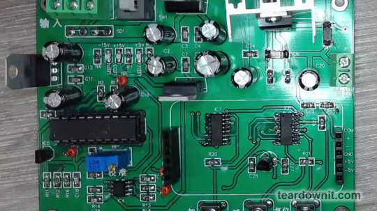
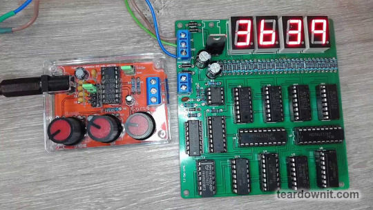
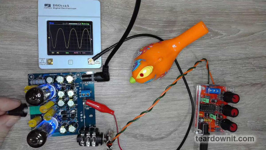
Today's example is a digitally controlled voltage regulator module that could be used in a lab power supply. The workhorse here is the LM317T chip, which has the DAC0832 digital-to-analog converter at its core.
The DAC0832 is a pretty advanced chip, with not one but two latches arranged in sequence. This setup allows it to store digital data from the microprocessor bus and convert it to an analog value at just the right moment.
In the post about the 74HC374 latch, we used it to freeze the readings on seven-segment displays for a second while counting input pulses.
After a second, the data from the counters was sent out to the display decoders, showing the frequency of the input signal measured a second earlier. Meanwhile, the next count of pulses was happening. This made for a good frequency counter.
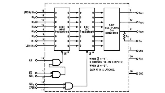
Each of the two latches in the DAC0832 can be made transparent, meaning asynchronous. In this mode, data from the input instantly appears in the output.
A logic high on the ¬LE (¬LATCH ENABLE) pin is needed to set the input latch to transparent asynchronous mode. You could call it LATCH DISABLE without the ¬ sign.
¬LE = ILE & (¬¬CS & ¬¬WR1) = ILE & ¬(¬CS | ¬WR1).
In simpler terms, you need a logic high on the ILE (INPUT LATCH ENABLE) input and a logic low on at least one of the two inputs, ¬CS (¬CHIP SELECT) or ¬WR1 (¬WRITE1). The ¬WRITE1 and ¬WRITE2 inputs are used for strobe signals.
For the 8-bit DAC latch register, the logic for ¬LATCH ENABLE is more straightforward:
¬LE = ¬¬XFER & ¬¬WR2 = ¬(¬XFER | ¬WR2).
So, you need a low logic level on at least one of the inputs: ¬XFER (¬TRANSFER) or ¬WR2 (¬WRITE2).
The heart of the DAC0832 is the analog-to-digital converter. This analog multiplexer switches precision silicon-chromium resistors deposited on a silicon chip.
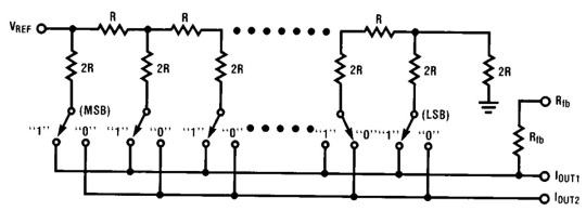
This manufacturing technique ensures high accuracy and temperature stability, which is why we use DAC chips in our favorite high-fidelity audio gear.
Plus, a multiplexer can work much faster than pulse-width modulation (PWM) analog-to-digital conversion, which we often use in Arduino DIY projects.
Also, PWM produces square pulses with different duty cycles with a broad frequency spectrum. The frequencies might be inaudible, but their interference with other frequencies in the device can create audible noises, which can be pretty unpleasant.
The homemade tube amplifier article mentioned that asymmetrical and softly clipped waveforms sound pleasant and musical to human ears because they're full of even harmonics.
But a square, symmetrical waveform has many odd harmonics, which aren't so nice to listen to, especially when they create dissonance with the overtones of other sounds played at the same time.

The DAC0832 needs an external operational amplifier to convert the current through switched precision resistors into an output voltage.
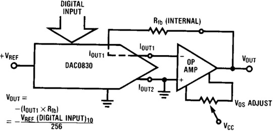
We'd probably go with the NE5532 for audio output, which we used for a simple, affordable, and high-quality headphone amp.

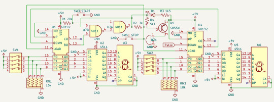
But the good old LM358 will do fine for a power supply. Here, op-amp IC4A converts the output current of the DAC0832 into voltage, and IC4B amplifies the resulting signal by six times.
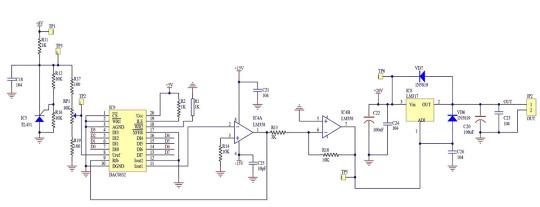
The TL431 chip generates the DAC0832's reference voltage, which is adjusted with the potentiometer RP1. The voltage ranges from 5×1100/1200=0.42V to 4.58V.
The output of IC4B is connected to the adjustment input of the LM317. Therefore, this chip's output voltage, and therefore our homemade power supply's, will be 1.25 volts higher than IC4B's.
So, the output voltage formula is:
Vout = 1.25 + 6 * Vref * DIGITAL INPUT / 256 = 1.25 + 0.024 * Vref * DIGITAL INPUT.
Adjusting the reference voltage can change the increment and decrement steps when pressing the corresponding buttons on the power supply's front panel.
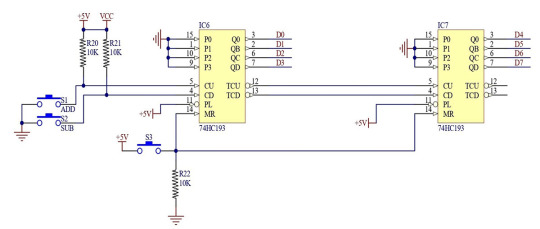
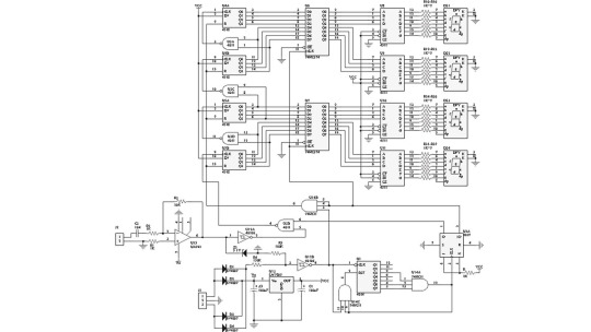
The digital value for converting to a voltage is set by two 74HC193 four-bit up/down counters.
These are presettable counters, similar to the ones we used as registers in our DIY 4-bit CPU.
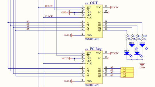
Each CPU's four registers used one SN74HC161L chip as a latch. The increment function was only used in the program counter (PC) register. The other three registers disabled it by grounding the CEP and CET control inputs.
We used the decrement function in a countdown timer that could be set to any number of seconds from 0 to 99.
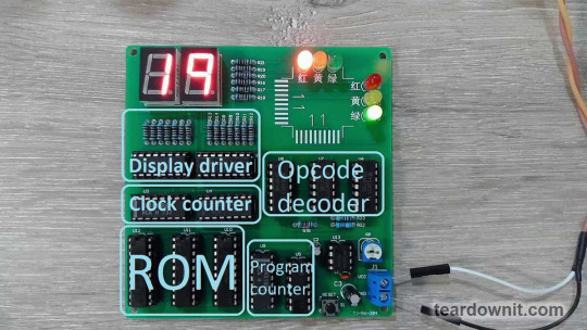
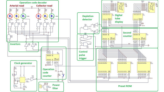
Thanks to the preset function, the chosen value from the PRESET ROM of our electronic traffic light tells the second counter how long the current signal combination should last. The decrement function was also used there.
In today's power supply, we do not use the preset function but both increment and decrement counting. There's also a reset button to set both counters to zero.
Accordingly, the digital-to-analog converter will also be set to zero since both of its internal latches are permanently in transparent asynchronous mode.
To lock the chip in this mode, the ¬CS, ¬WR1, ¬WR2, and ¬XFER control inputs are soldered to ground.
We could make a power supply with non-volatile preset memory if we used a microcontroller instead of up/down counters. The microcontroller's analog-to-digital converter could be used for the voltmeter and ammeter.
And if the microcontroller doesn't have enough pins to connect the 8-bit DAC data bus, we could use a shift register for serial data transfer.
In this case, the DAC0832's latch registers could be very handy if the shift register doesn't have a built-in latch.
After all, to convert a binary number into a voltage, you must wait until the binary number is fully received from the microcontroller via the serial bus. Otherwise, you’d get meaningless voltage jumps, which are unacceptable in a power supply.
0 notes
Text
🌟 The World of Electronics Engineering: A Quick Dive 🌟
Welcome to the fascinating universe of Electronics Engineering! 🌐 This field is the backbone of our digital age, powering everything from our smartphones to the satellites orbiting the Earth. Here’s a quick rundown on what makes electronics engineering so essential���and exciting! 🚀
🛠️ What is Electronics Engineering?
Electronics engineering focuses on designing, developing, and testing electronic devices and systems. It includes areas like circuit design, signal processing, communication systems, and embedded systems. Electronics engineers work to turn abstract theories into tangible technologies that revolutionize daily life.
🔑 Key Areas of Study:
Analog and Digital Circuits: Understanding and building circuits that can process analog or digital signals is fundamental.
Microprocessors and Microcontrollers: These tiny computers are at the heart of many devices, enabling automation and control in everything from home appliances to industrial machines.
Communication Systems: This includes designing networks for data transmission, like Wi-Fi, 5G, and IoT.
Power Electronics: Essential for energy-efficient systems, renewable energy solutions, and electric vehicles.
Embedded Systems: Specialized computer systems built into devices to perform dedicated functions.
🚀 Why Pursue Electronics Engineering?
Electronics engineering blends creativity and technical skill to solve real-world problems. This field constantly evolves, pushing the limits with new tech trends like AI, IoT, quantum computing, and renewable energy.
🌍 Career Impact
Electronics engineers play a vital role in nearly every industry—healthcare, telecommunications, automotive, space exploration, and more. As tech advances, the demand for skilled engineers continues to grow, opening paths for impactful and high-paying careers.
⚙️ Tools of the Trade:
Multimeters and Oscilloscopes for testing and measuring electrical properties.
CAD software like Altium Designer or KiCAD for designing PCB layouts.
Microcontroller platforms like Arduino or Raspberry Pi for prototyping projects.
👨🔬👩🔬 Ready to Jump In?
Whether you’re a student, a hobbyist, or thinking of switching careers, electronics engineering has something for everyone. Start by experimenting with simple circuits, learn the basics of coding, and dive into DIY projects that excite you. 🔋💡
Electronics engineering is shaping the future, one circuit at a time. 🌐 Will you be part of the next wave
0 notes
Text
Controlling Multiple Relays with Arduino: A Comprehensive Guide
Introduction
Relay modules are essential components in the world of electronics, allowing you to control high-power devices with low-voltage signals. When combined with the versatility of Arduino, you can create a wide range of automated systems. In this blog post, we'll explore how to control multiple relay modules using an Arduino board.
Understanding Relay Modules
A relay module typically consists of one or more relays, each with a control pin and a pair of output terminals. By applying a low voltage (usually 5V) to the control pin, you can switch the relay, connecting or disconnecting the output terminals. This allows you to control devices that require higher voltages and currents than the Arduino can directly provide.
Required Components
Arduino board (e.g., Uno, Nano)
Relay module (2-channel or more)
Jumper wires
Breadboard (optional)
Power supply (5V DC)
Circuit Diagram
Power Supply: Connect the 5V and GND pins of the relay module to the 5V and GND pins of the Arduino, respectively.
Relay Control: Connect the control pins of the relays to digital pins on the Arduino (e.g., pins 2, 3, 4, and 5).
Arduino Code
const int relayPins[] = {2, 3, 4, 5}; // Array to store relay pin numbers
void setup() {
for (int i = 0; i < 4; i++) {
pinMode(relayPins[i], OUTPUT);
}
}
void loop() {
// Control the relays as needed
digitalWrite(relayPins[0], HIGH); // Turn relay 1 ON
digitalWrite(relayPins[1], LOW); // Turn relay 2 OFF
// ... and so on
}
Explanation
Pin Definition: An array relayPins is used to store the pin numbers connected to the relay control pins.
Setup:
pinMode(relayPins[i], OUTPUT): This line sets each pin in the array as an output pin.
Loop:
digitalWrite(relayPins[i], HIGH/LOW): This line controls the state of a specific relay by setting the corresponding pin to HIGH (ON) or LOW (OFF).
Expanding the Functionality
Sensor-Based Control: Use sensors (e.g., temperature, light, motion) to trigger relay actions based on specific conditions.
Timer-Based Control: Employ the millis() function to implement time-based switching.
Remote Control: Combine with wireless modules (e.g., Bluetooth, Wi-Fi) to control the relays remotely.
Multiple Relay Modules: Connect multiple relay modules to the Arduino to control more devices.
Safety Considerations
Voltage and Current Ratings: Ensure that the relay module's voltage and current ratings are suitable for the load you're controlling.
Heat Dissipation: If controlling high-power loads, consider using heat sinks or other cooling measures.
Proper Wiring: Double-check all connections to avoid short circuits and potential damage.
By mastering the art of controlling multiple relay modules with Arduino, you can create a wide range of innovative projects, from home automation systems to industrial control applications.
Would you like to delve deeper into a specific application or have any other questions about relay module control with Arduino?
0 notes
Text
Get Arduino Atmega 2560 R3 Board at Affordable Price in Ainow

With the MAX3421e IC, the Mega 2560 Atmega2560-16au compatible with Arduino is a microcontroller board based on the Arduino Atmega 2560 R3.
With a total of 54 digital input/output pins (including 15 PWM outputs), 16 analog inputs, and 4 UARTs, the MEGA ADK is jam-packed with features. It also boasts a 16 MHz crystal oscillator and comes equipped with a USB connection, power jack, ICSP header, and reset button. Based on the Arduino Atmega 2560 r3, this board shares many similarities with its counterparts, including the ATmega8U2 program that serves as a USB-to-serial converter. In fact, the Mega ADK revision 3 even includes a resistor that conveniently pulls the 8U2 HWB line to ground for easier DFU(Device Firmware Upgrade) mode access.
New features on the board include:
As part of the 1.0 pin-out, the shields will be able to adjust to the voltage provided by the board by adding SDA and SCL pins near the AREF pin and two new pins near the RESET pin, the IOREF. Shields in the future will be compatible with boards that use AVR, which operate at 5V, and Arduino Due, which operates at 3.3V. The second pin, which is not connected, will be used for future purposes.
Circuit with a stronger RESET.
A USB connection or an external power supply can be used to power the Arduino Atmega 2560 R3 Android Accessory Development Kit (ADK). An AC-to-DC adapter (wall-wart) or battery can be used to supply external (non-USB) power. An adapter can be connected by plugging a 2.1mm center-positive plug into the board’s power jack.
GND and Vin pin headers on the POWER connector can be inserted with battery leads. Since the Mega R3 Android Accessory Development Kit (ADK) is a USB Host, the phone will attempt to draw power from it when it needs to charge. When the ADK is powered over USB, 500mA is available for the phone and board.
Features and specifications:
Arduino Atmega 2560 r3 :
Atmel is the programmer
Microcontroller ATmega2560.
A total of 54 digital input/output terminals (14 of which have programmable PWM outputs) are available.
There are 16 analog inputs.
There are four UARTs (hardware serial ports).
A crystal clock with a frequency of -16 MHz.
A bootloader allows sketches to be downloaded via USB without having to go through an external writer.
-Powered by USB or external power supply (not supplied). The device will automatically switch between power sources.
A heavy gold plate construction is used.
The clock speed is 16 MHZ.
Bootloader uses 8 KB of the 256 KB flash memory.
The operating voltage is 6 x 12 volts.
Mega 2560 Arduino cable:
It is hot pluggable.
-Compatible with PCs.
Strain relief and PVC overmolding ensure error-free data transmissions for a lifetime.
-Aluminum under-mold shield helps meet FCC requirements for KMI/RFI interference.
-Filled and braided shield conforms to fully rated cable specifications and reduces EMI/FRI interference.
Error-free, high-performance transmission.
Case made of transparent acrylic:
MEGA2560 R3 (unassembled) compatible.
It is possible to adjust the cover.
Transparent color.
Acrylic is the material used.
The power of
The external power regulator has a maximum capacity of 1500mA. Of this, 750mA is reserved for the phone and MEGA ADK board, while the remaining 750mA is dedicated to any attached actuators and sensors. To use this amount of current, a power supply must be able to provide at least 1.5A. While the board can run on an external supply ranging from 5.5 to 16 volts, it is recommended to use between 7 and 12 volts. If supplied with less than 7V, there may be insufficient voltage output from the 5V pin, potentially causing instability in the board. On the other hand, using more than 12V may result in overheating of the voltage regulator and potential damage to the board components.
What follows is:
This pin is used to supply voltage to the Arduino board when it is powered by an external power source rather than 5 volts from the USB connection or another regulated source.
This pin generates a regulated 5V from the board’s regulator. The board can be powered via the DC power jack (7-12V), USB connector (5V), or VIN pin (7-12V). If you supply voltage via the 5V or 3.3V pins, you bypass the regulator and can damage your board. Please do not do so.
The onboard regulator generates 3.3 volts. Maximum current draw is 50 milliamps.
The ground pins are GND.
The Arduino board’s IOREF pin serves as a voltage reference for the microcontroller. In a properly configured shield, you can determine the voltage of the IOREF pin and select an appropriate power source or enable voltage translators to work with either 5V or 3.3V outputs.
The memory
It has 256 KB of flash memory for storing code (of which 8 KB is used for the bootloader), 8 KB of SRAM, and 4 KB of EEPROM (which can be read and written).
The inputs and outputs
By using pin Mode(), digital Write(), and digital Read() functions, each of the Arduino Atmega 2560 R3 Android Accessory Development Kit (ADK)’s 50 digital pins can be used as inputs or outputs. There is an internal pull-up resistor of 20-50 Ohm on each pin. They operate at 5 volts. They can provide or receive a maximum current of 40 mA. Some of the pins have specialized functions:
Serial 0: 0 (RX) and 1 (TX), Serial 1: 19 (RX) and 18 (TX), Serial 2: 17 (RX) and 16 (TX), Serial 3: 15 (RX) and 14 (TX). Connected to the ATmega8U2 USB-to-TTL Serial chip on pins 0 and 1.
External Interrupts: 2 (interrupt 0), 3 (interrupt 1), 18 (interrupt 5), 19 (interrupt 4), 20 (interrupt 3), and 21 (interrupt 2). An interrupt can be triggered on a low value, a rising or falling edge, or a change in value using the attach Interrupt() function.
Providing 8-bit PWM output with the analog Write() function for PWM values 2 to 13 and 44 to 46.
SPI: 50 (MISO), 51 (MOSI), 52 (SCK), 53 (SS). These pins support SPI communication using the SPI library. They are also broken out on the ICSP header, which is physically compatible with Uno, Duemilanove, and Diecimila.
MAX3421E is the USB host.
The Max3421E
The following pins are used to communicate with Arduino via the SPI bus:
Seven (RST), fifty (MISO), fifty one (MOSI), and fifty two (SCK) are digital.
You should not use Digital pin 7 for inputs or outputs because it is used to communicate with MAX3421E
PJ3 (GP_MAX), PJ6 (INT_MAX), PH7 (SS) are not broken out on headers.
A built-in LED is connected to digital pin 13. When the pin is HIGH, the LED is on, when it is LOW, it is off.
Supports TWI communication using the Wire library. These pins are not in the same location as the Duemilanove or Diecimila TWI pins.
Android Accessory Development Kit (ADK) with Arduino Atmega 2560 R3 has 16 analog inputs, each with a resolution of 10 bits (i.e. 1024 different values). It is possible to change the upper end of the range of the pins by using the AREF pin and analog Reference() function. Other pins on the board include:
Reference voltage for analog inputs. Use with analog reference.
Reset. This line is typically used to add a reset button to shields which block the board’s reset button.
The communication process
The Arduino Atmega 2560 R3 Android Accessory Development Kit (ADK) offers various communication options, including connecting with a computer, another Arduino, or other micro-controllers. The ATmega2560 has four hardware UARTs for TTL (5V) serial communication. Additionally, the board has an ATmega8U2 that uses USB to provide a virtual com port for computer software. For Windows machines, a .inf file may be needed but OSX and Linux machines will automatically detect the board as a COM port. In the Arduino software, there is a serial monitor feature for sending and receiving simple textual data from the board.
When data is transmitted via the ATmega8U2/16U2 chip and USB connection to the computer (but not for serial communication on pins 0 and 1), the board’s RX and TX LEDs flash. Any of the MEGA ADK’s digital pins can be serialized with a software-serial library. TWI and SPI communication are also supported by the ATmega2560. The Arduino software contains a Wire library to simplify TWI communication, see Wire library for details. For SPI communication, use the SPI library.
The USB host interface given by MAX3421E IC allows Arduino MEGA ADK to connect and interact with any type of device with a USB port. It allows you to interact with many types of phones, control Canon cameras, and interface with keyboards, mice, and gaming controllers such as Wiimote and PlayStation 3.
The programming language
For details, see the reference and tutorials. You can program the Mega R3 Android Accessory Development Kit (ADK) with Arduino software (download). You don’t need an external hardware programmer to upload new code to the ATmega2560 on the MEGA ADK since it comes preburned with a boot-loader (just like the Arduino Atmega 2560 r3). The STK500v2 protocol (references and C header files) is used for communication.
You can also bypass the bootloader and program the microcontroller through the ICSP (In-Circuit Serial Programming) header using Arduino ISP or similar; see these instructions for details. Atmega8U2 firmware source code is available in the Arduino repository. An ATmega8U2 is loaded with a DFU bootloader, which can be activated by:
The Rev1 boards have the following features:
Resetting the 8U2 requires connecting the solder jumper on the back of the board (near the map of Italy).
Rev2 and later boards have a resistor pulling the 8U2/16U2 HWB line to ground, making it easier to put into DFU mode. To load a new firmware, you can use the FLIP software (Windows) or the DFU programmer (Mac OS X and Linux). If you prefer, you can use the ISP header with an external programmer (overwriting the DFU bootloader). See this user-contributed tutorial for more information.
Reset (automatic) software
The Arduino Atmega 2560 r3 ADK has been designed to reset by software from a connected computer instead of requiring a physical press of the reset button before an upload. This is achieved by connecting one of the hardware flow control lines (DTR) of the ATmega8U2 to the reset line of the ATmega2560 through a 100 nano-farad capacitor. Whenever this line is asserted, causing it to drop low, the chip will be reset momentarily. The upload button in the Arduino environment makes use of this feature, enabling you to easily upload code without needing to manually press the reset button.
As a result, the boot-loader’s timeout can be reduced since DTR can be synchronized with the upload initiation. This arrangement also has additional effects when the MEGA ADK is linked to a computer running Mac OS X or Linux. Upon being connected to software via USB, the board resets and enters bootloader mode for about half a second. During this time, any non-code data will be disregarded by the programmed bootloader, but it will capture the first few bytes of data transmitted after the connection is established.
Ensure that the software your sketch is communicating with allows for a brief pause after establishing the connection before sending any initial data. The MEGA ADK has a trace that can be removed to disable the auto-reset function. Connect the pads on either side of the trace to re-enable it, labeled as RESET-EN. Alternatively, you can disable the auto-reset by connecting a 110-ohm resistor from 5V to the reset line; additional information can be found in this forum thread.
Over-current protection for USB devices
A resettable polyfuse protects your computer’s USB ports from shorts and overcurrents with the Arduino Atmega 2560 R3 Android Accessory Development Kit (ADK). In spite of the fact that most computers have their own internal protection, a fuse provides an additional layer of protection. When more than 500 mA is applied to the USB port, the fuse automatically stops the connection.
Shield compatibility and physical characteristics
The Mega R3 Android Accessory Development Kit (ADK) PCB has a maximum length and width of 4 inches and 2.1 inches respectively. The USB connector and power jack extend beyond the length, while three screw holes are available for surface or case attachment. It is important to note that the distance between digital pins 7 and 8 is 160 mil, which is not an even multiple of the standard 100 mil spacing for the other pins. Additionally, the MEGA ADK can be used with most shields designed for the Uno, Diecimila or Duemilanove boards.
The digital pins 0 to 13 (as well as the adjacent AREF and GND pins), analog inputs 0 to 5, the power header, and the ICSP header are all positioned in the same spot. In addition, the main UART (serial port) is located on the same pins (0 and 1); as are external interrupts 0 and 1 (pins 2 and 3). SPI is also available through the ICSP header on the MEGA ADK and Duemilanove / Diecimila.
On the MEGA ADK (20 and 21), I2C and D are not located on the same pins.
1 note
·
View note
Text
Introduction Model rocketry is an exciting hobby that combines both technology and creativity. Model rocketry enthusiasts are always looking for new and innovative ways to improve their rockets, and one such way is by using an Arduino-based altimeter. An altimeter is a device used to measure altitude or height above sea level. The Arduino-based altimeter is an electronic device that utilizes the power of Arduino microcontrollers to record and store the altitude data of your model rocket's flight. The Arduino-based altimeter can be used for a range of things, such as measuring the maximum altitude of your rocket and ensuring that it deploys its parachute at the correct time. In this article, we’ll provide you with an in-depth guide on how you can build a model rocket altimeter using Arduino. How to Build a Model Rocket Altimeter using Arduino To build an Arduino-based altimeter for your model rocket, you will need the following components: - Arduino Uno R3 board - BMP280 digital pressure sensor - Lipo battery - PCB board - Resistors - Jumper wires - LEDs Once you have all these components, follow these steps to construct your model rocket altimeter: Step 1: Assemble the circuit Using the PCB board, assemble the circuit according to the schematics provided. Start by connecting the BMP280 pressure sensor to the Arduino Uno board. You can do this by connecting the SDA and SCL pins of the sensor to the A4 and A5 pins of the board. Additionally, connect the VIN and GND pins of the sensor to the 5V and GND pins of the board, respectively. Step 2: Add a switch To power the altimeter on and off, add a switch. The switch should be connected to the VIN and GND of the Lipo battery. Step 3: Connect the LEDs Connect the LEDs to the digital pins of the board, ensuring that the resistors are used to limit the current that flows through them. Step 4: Upload the code Once you have assembled the circuit, upload the code to the Arduino Uno board. The code is readily available online, and you can find it on the Arduino IDE or in various online forums. Step 5: Power the altimeter The altimeter should now be powered on, and you can test it by connecting it to the Lipo battery. You can then place the altimeter into your model rocket, and it will record and store the altitude data during the rocket's flight. FAQs About Model Rocket Altimeter Arduino 1. What is the maximum altitude the Arduino-based altimeter can measure? The BMP280 pressure sensor used in this altimeter has a range of 300-1100 hPa, equivalent to an altitude range of approximately 9,000 meters above sea level. However, the maximum altitude that can be measured by the altimeter is dependent on factors such as the quality and accuracy of the sensor, the barometric pressure of the location of the rocket launch, and the sensitivity of the pressure sensor. 2. How can I calibrate my altimeter? To calibrate your altimeter, you will need to use a known elevation location such as a mountain or hilltop. Once you get to this location, insert a battery and turn on the altimeter, then wait for it to stabilize before writing down the altitude data. Repeat this process a few times, and then calculate the average deviation between the readings. You can then adjust the calibration constants in the code to ensure that the altitude measurement is accurate. 3. Can the altimeter record temperature? The BMP280 pressure sensor used in this altimeter can measure temperature in addition to pressure, meaning that the altimeter can record both altitude and temperature data. You can even customize the code to record and store temperature data, in addition to the altitude data. Conclusion An Arduino-based altimeter for model rockets is an innovative way to record and store the altitude data of your rocket's flight. By using this altimeter, you can ensure that your model rocket deploys its parachute at the correct time, and you can also record its maximum altitude. Building an Arduino-based altimeter for model rockets is straightforward and requires only a few components.
With the right skills and knowledge, you can also customize the code to record other data such as temperature. If you have any questions or comments Please contact us on our contact page or via our Facebook page. #model #rocket #altimeter #arduino
0 notes
Text
Let me introduce my current main WIP. It's not fandom related, it's for my model railroad, and it's not yet finished.
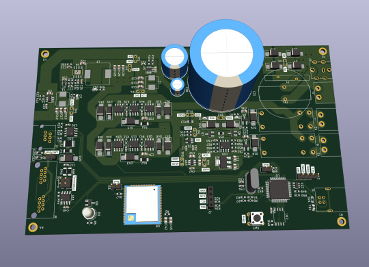
This is a rendering of a circuit board that I'm designing at the moment. It will be a DCC command station. My model railroad is run digitally, which means the tracks carry digital signals that tell each locomotive and switch individually how to run, which lights to turn and so on. The command station is the device that generates that. I have a number of different layouts, one of which has a good command station, one of which has a crappy old one, and the final one isn't even digital yet. So this will be the one that solves all issues for me, hopefully.
The design above isn't finished yet, and even the parts that are are not yet fully representative. The different capacitors are just there as options; some screen print overlaps; and some components (in particular all plugs and the relays that control the programming track) don't have 3D models so they don't show up.
Planned features:
Four layer board
10-25 V DC output, software controllable
Up to 5A output power, limited mainly by the main switching regulator.
Input 15-25V either AC or DC with polarity protection, selectable with some solder bridges (not yet in there). Optionally you can also bypass the main power regulator with another solder bridge (that I haven't added yet); useful in case you use e.g. a laptop power supply with a switchable voltage and don't need any regulation after that.
Railcom support
USB connection; not yet sure what for, but the main chip I'm using has USB support and I have some spare USB connectors here, so in it goes.
Speaking: The chip is an STM32L433RCT6P, chosen because I found it in stock at an electronics distributor. 64 kB RAM, 256 kB EEPROM, with support for an additional up to 256 MB externally (there's a spot for that on the board) and lots of fun extras that I don't technically need. It has an FPU! I don't need an FPU, but I will definitely do some floating point math computation on it just for fun.
Main external connection is WLAN using an ESP32 WROOM U module. I haven't decided on the housing, but I may go for extruded aluminum, so it's the U version that allows and requires an external antenna
It supports XBUS/XpressNet connections for old throttles from Lenz and Roco that I should probably throw away, but I paid good money for them, dang it.
It supports CAN for LCC / OpenLCB. I may not populate this part on all boards that I'm building, because I haven't actually decided whether I am interested. But the chip has CAN functionality built in, so why not.
There's an I2C connection to connect a cheap tiny OLED display for status messages.
Test points for all important signals (in particular the different internal voltage levels; yes, there is 3.3V, A3.3V and -3.3V and I need all of them).
Stuff still to add:
I will add pin headers (or space for pin headers anyway) for all the remaining pins on the STM32, and perhaps some on the ESP32, for future expansions.
Status LED and stop/go button on the front
Wire it all up, maybe move some stuff (mostly the STM32 around), which will cause all sorts of fun new routing issues.
Adjustments to make the jacks line up with the front panel once I've decided on a housing.
Features I'm not considering adding:
s88. I vaguely know what it is but I don't have any devices like that, and if that ever changed I could probably build (or perhaps buy) a converter that connects them via CAN.
Other buses like LocoNet.
Ethernet. I don't need it and it's actually more expensive than WLAN in this day and age.
In terms of software, I'm planning to use DCC-Ex on it. The whole project actually started out as a DCC-Ex shield, but once I realised that this wouldn't fit, I decided to make it standalone. Now, DCC-Ex is designed for Arduino, not STM32, and it doesn't support XpressNet, nor OpenLCB, nor Railcom, and their Wifi protocol is pretty weird and annoying which will be an issue (I'm planning to write my own control app for iPhone for it), so I'll probably change that or just replace it with the z21 one… so really, the software will not look a lot like DCC-Ex once I'm done with it.
Will this all work? I have honestly no idea. I mean, I'm fairly confident, I'd have given up on this long ago otherwise, but I have no guarantees either way until I've spent a lot of money on components and circuit boards and start soldering. Turns out doing it this way is not really cheaper than just buying a half-way decent one. That's what makes it exciting, though!
If it does work, obviously this will be released as open source. But it's still going to be a few days (more realistically weeks) before it's even ready to order the parts, and then a lot of soldering (current BOM stands at 194 actual components), and then a lot of software development before it's ready for that.
5 notes
·
View notes
Text
Thrift store find, and a project:

Got this Alesis QX25 MIDI controller in as-is condition for $12. The most obvious problems when I got it were that the fader cap and one rotary encoder knob were missing, and one of the black keys was broken. In addition, there were solfege stickers on the keys, implying the previous owner was pretty young; that impression was backed up when I opened it to find maybe half a container of assorted glitter inside.
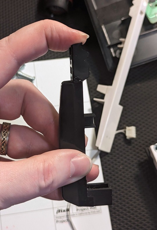
The fader cap I haven't come up with yet, and I've put a temporary knob on the encoder — the one at the far right — and I was able to partially disassemble the keybed and glue the key back together. (I'm using Gorilla Glue's superglue formulation, which is supposed to be better than usual cyanoacrylates at bonding plastics; if this doesn't hold, I know where to order replacements.) From a quick once over, the current status is that some of the tact switches are broken somehow — the ones, at least, for octave up and transpose down don't work. I've only given those the most cursory inspection, so I don't know if it's the switches themselves or something in the wiring; I'll have to see if my big box of tact switches has anything I can swap in for them.
But the "project" part is the part that has me enthused. Unlike a lot of more recent MIDI controllers, this one has both a USB jack for connecting to a computer and a 5-pin DIN jack for traditional MIDI instruments. It's also got a lot of spare room inside the case. So I'm looking at taking an Arduino or a Teensy and some little digital-to-analog converters and adding the ability to output CV and gate signals for modular synthesizers. Basically the Arduino will listen to the MIDI signal and interpret that; the minimal feature set is a single note off channel 1, just the CV and gate corresponding to the most recently struck key, but may expand to multiple notes and/or handling the drum pads as their own gate/trigger outs, and probably an extra CV out that can follow the mod wheel or pitch bend.
I'm debating which DACs to use. I have some lying around — the spoils of a time when Linear, Analog Devices, and Maxim were separate companies, and they, Microchip, and Texas Instruments would give out free samples if you had a plausible-sounding company name — but a lot of them aren't particularly well-suited for this. I want to run everything off the existing 5V supply — either a wall wart or USB — and not need elaborate external analog circuits to do things. I'm looking at the MCP4811, a single-channel 10-bit device, which has the advantage of an internal voltage reference at 2.048V, and a ×2 output, for a full range of 0V-4.096V that's very reliable even when run off a unreliable 5V power supply, like the keyboard's USB power input.
(In an ideal world, I'd have a perfect 1v reference, and a precision adder, so that the full precision of the part, all the bits, could be applied to just the 0-1V range, and then I could add single volts as needed to specify the octave. If we're calling 0V C0, then with the 10-bit setup over the 4.096V spread, you have to use value 396 to get G1, and you're imperceptibly sharp; with ten bits over a single volt, you'd use value 597 and add an extra volt and you'd be... slightly closer but flat this time. So the ideal world can fuck itself, and I'll see how the thing I actually have works.)
2 notes
·
View notes