#PrecisionLinearStages
Explore tagged Tumblr posts
Visit Tumblr Blog
Explore Tumblr blogs with no restrictions, modern design and the best experience.
Last Seen Tumblr Blogs


Fun Fact
After the announcement of the deal with Yahoo!, there were 170K signatures of unhappy Tumblr users petitioning to prevent the sale in 2013.
Text
Multi Axis Linear Stages Are Ready for Delivery to UK
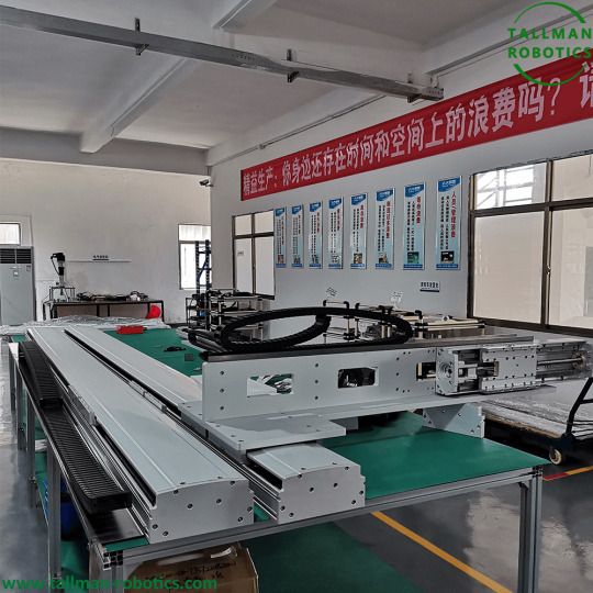
Multi-axis linear stages achieve high positioning accuracy and repeatability through a combination of design features, components, and control systems. How do multi-axis linear stages achieve high positioning accuracy and repeatability?

Here are some key factors that contribute to their precision: 1. Mechanical Design: Multi-axis stages are built with precision in mind. They incorporate high-quality materials and construction techniques to ensure rigidity, stability, and minimal play or backlash in the mechanical components. This reduces unwanted vibrations and ensures accurate positioning. 2. Linear Guides and Bearings: These stages utilize high-precision linear guides and bearings to provide smooth and precise linear motion. These components minimize friction and ensure consistent movement, contributing to accuracy and repeatability. 3. Drive Mechanisms: The choice of drive mechanism plays a crucial role in achieving accuracy. Multi-axis stages can use various drive systems such as stepper motors, servo motors, or linear motors. These drive mechanisms are selected based on the requirements of the application, with considerations for speed, torque, precision, and smoothness of motion. 4. Feedback Systems: To achieve precise positioning, multi-axis stages often incorporate feedback systems such as linear encoders or optical scales. These systems provide real-time position feedback to the control system, allowing for closed-loop control. Feedback enables the control system to correct for any errors or deviations, resulting in higher accuracy and repeatability. 5. Control Systems: Multi-axis stages are typically integrated with control systems that allow precise motion control. Advanced control algorithms, such as PID (Proportional-Integral-Derivative) control, are employed to optimize the positioning accuracy and reduce errors. The control systems can be manual, computer-based, or even programmable, depending on the complexity and requirements of the application. 6. Calibration and Compensation: Manufacturers of multi-axis stages often perform calibration procedures to ensure accurate positioning. Calibration involves mapping the actual position of the stage to the commanded position and applying compensation techniques to correct any deviations or non-linearities. This calibration process further enhances the accuracy and repeatability of the stages. 7. Environmental Considerations: Multi-axis stages are designed to minimize the impact of environmental factors on positioning accuracy. They may incorporate features such as dust seals, temperature compensation, or vibration isolation to mitigate the effects of temperature variations, contaminants, or external disturbances. By combining these design features, high-precision components, feedback systems, advanced control algorithms, and calibration procedures, multi-axis linear stages can achieve the high positioning accuracy and repeatability required for demanding applications in fields such as microscopy, metrology, semiconductor manufacturing, and precision assembly. You are welcome to https://www.youtube.com/@tallmanrobotics to watch our video centre for more projects or visit our website to check other series or load down e-catalogues for further technical data. Read the full article
#MotorizedMulti-AxisStage#Multi-AxisMotorized3-AxisStage#PrecisionLinearStages#PrecisionXYandXYZStages
0 notes
Text
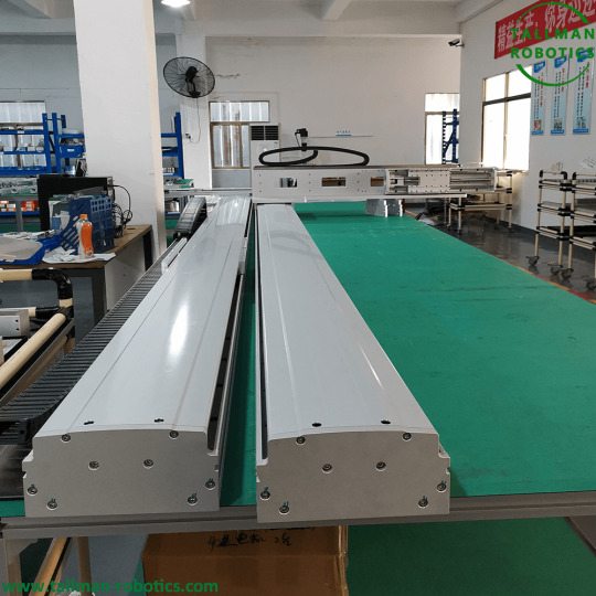
Linear Translation Stages are Finished for Germany Clients.
Linear Translation Stages have been Finished and will be delivered to Germany Clients.You are welcome to visit our download centre to check E-catalogues or watch our video centre to check more projects.
How to adjust the preload of ball screw nut. Ball screw nut pair is a high-precision transmission device. It uses rolling friction screw instead of sliding friction screw, which has the advantages of small wear, high transmission efficiency, stable transmission, long service life, high accuracy and low temperature rise. Select high-quality screw to identify titanium Hao. Because the ball screw nut pair has the outstanding advantages of small motion friction and easy to eliminate transmission clearance, it brings great benefits to the performance improvement of electromechanical integration system. Pre tightening is to prevent the ball from slipping. The self-locking property of the ball screw nut pair is poor, which can be said to be absent. It is easy to fall off without pre tightening. https://youtube.com/shorts/ctaMxDnmOC8?feature=share There are four common methods for ball screw preloading: - Double nut gasket type pre tightening The mechanism of this method is simple and reliable. Good rigidity and most widely used. The form of adding gasket between the double nuts can be adjusted in advance by a professional manufacturer according to the user's requirements. It is very convenient to unload when using. - Double nut threaded pre tightening Use the external thread on one nut to adjust the relative axial position of the two nuts through the round nut to achieve pre tightening. - Double nut tooth difference pre tightening On the flanges of the two nuts, cut out the gears with a tooth number difference of 1. The two gears mesh with the corresponding internal gear rings at both ends. The internal gear rings are fastened on the nut seat with screws. By rotating one of the nuts, the mutual positions of the two nuts are changed to adjust the clearance and apply the preload. - Single nut variable lead self preloading The internal thread raceway of the nut will produce a lead sudden change on the middle circle, so that the balls at the left and right ends will be axially displaced after assembly to realize pre tightening. The purpose of eliminating the axial clearance of the ball screw nut pair is to increase the preload and reduce the empty stroke in the reverse direction, so that there is no reverse dead zone, and improve the transmission rigidity and transmission accuracy. Not all ball screws(in Linear Translation Stages) are pre tightened, mainly according to the accuracy requirements. Generally, the pre tightening accuracy is high and the load capacity is large. The pre tightening is graded. The selection is based on the use requirements. You can check the samples of different brands for details. Read the full article
#HighPrecisionPositioning#High-PrecisionLinearStages#LinearMotionStages#LinearRotaryStages#LinearTranslationStages#MiniatureLinearStages#MotorizedLinearStages#MotorizedXYLinearStage#PrecisionLinearStages#X-YStages
0 notes
Text
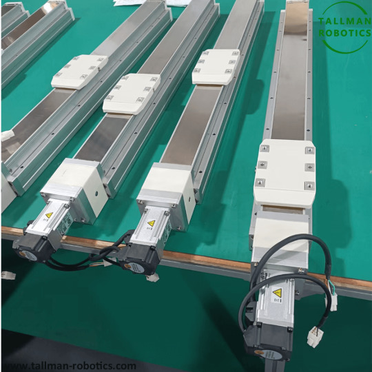
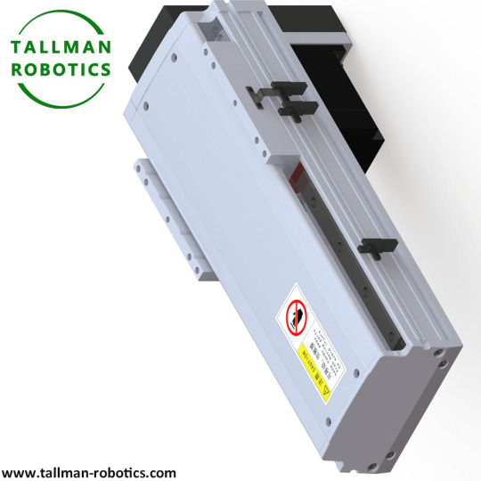
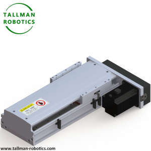
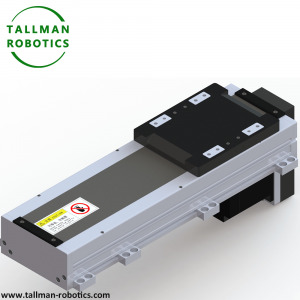
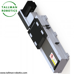
Ball Screw Driven Linear Modules
Ball Screw Driven Linear Modules You are welcome to visit our download centre to check E-catalogues or watch our video centre to check more projects. The transmission method of Ball Screw Driven Linear Modules is characterized by high repeatability, up to ±0.005mm, high accuracy and high load. Usually used in the production process with a certain precision in industrial production. In the selection process of the ball screw drive, attention should be paid to the selection of the screw, which is usually determined according to factors such as load, speed, and torque. Pay attention to the maintenance of the screw when using the linear module of the ball screw. After cleaning a long distance, clean dirt and grease should be replaced in time, usually every half a month. Ball screw is an ideal product that converts rotary motion into linear motion, or converts linear motion into rotary motion. The ball screw is composed of a screw, a nut and a ball. Its function is to convert rotary motion into linear motion, which is a further extension and development of ball screws. The important significance of this development is to change the bearing from rolling motion to sliding motion. Due to its small frictional resistance, ball screws are widely used in various industrial equipment and precision instruments.
What are the Basic Specification of Ball Screw Driven Linear Modules from Tallman Robotics Limited Model No Max Payload(kgs) Max Stroke (mm) Repeatability (mm) Drive Solution Motor Power (W) TMS30 4 400 ±0.01/±0.005 screw 30 TMS45 10 800 ±0.01/±0.005 screw 50/100 TMB45 4 800 ±0.04 belt 50/100 TMS62 20 1050 ±0.01/±0.005 screw 100/200/400 TMB62 16 2000 ±0.04 belt 100/200/400 TMS65 30 800 ±0.01/±0.005 screw 50/100 TMB65 4 800 ±0.04 belt 50/100 TMS85 50 1050 ±0.01/±0.005 screw 100/200/400 TMB85 16 2000 ±0.04 belt 100/200/400 TMS100 65 1050 ±0.01/±0.005 screw 100/200/400 TMB100 40 3500 ±0.04 belt 100/200/400 TMS135 110 1250 ±0.01/±0.005 screw 200/400/750 TMB135 42 3500 ±0.04 belt 200/400 TMS150 120 1500 ±0.01/±0.005 screw 400/750 TMB150 75 3500 ±0.04 belt 400/750 TMS170 130 1500 ±0.01/±0.005 screw 400/750 TMB170 75 3500 ±0.04 belt 400/750 TMS220 150 1500 ±0.01/±0.005 screw 750 TMB220 75 3500 ±0.04 belt 750 Ball Screw Driven Linear Modules are composed of multiple single-axis robots to realize multi-axis combination through different combination styles, to achieve applications such as Cartesian actuators, XYZ multi-axis actuators (XY table), and so on. It is widely used in the positioning, transfer, handling, inspection, dispensing, welding, cutting, etc. of LCD panels, semiconductors, home appliances, daily chemicals, automobiles, batteries and other fields. Related Knowledge: The main features of the application of the ball screw in the module. The ball screw is the most commonly used transmission element in machine tools and precision machinery. Its main function is to convert rotary motion into linear motion, or convert torque into axial repetitive force, and it has both high precision, reversibility and high Features of efficiency. Ball screw is also called ball screw and ball screw. 1) High positioning accuracy The ball screw pair realizes rolling friction between the nut and the screw by ball rolling. The motion of the rolling linear guide is realized by rolling of the steel ball. The friction resistance of the guide pair is small, the difference between dynamic and static friction resistance is small, and no crawling occurs at low speeds. . High repeat positioning accuracy, suitable for moving parts that frequently start or change directions. 2) Less wear Due to the low frictional energy consumption of rolling contact, the friction loss of the rolling surface is also reduced correspondingly, so the rolling linear guide system can be in a high-precision state for a long time. At the same time, the use of lubricating oil is also very small, which makes it very easy to design and use and maintain the lubrication system of the machine tool. 3) Long life For the nut of the ball screw pair, the screw hardness reaches HRC58-62, and the ball hardness reaches HRC62-66, and there is rolling friction between them, so higher fatigue life and accuracy life can be achieved. 4) Adapt to high-speed movement Due to the low friction resistance of the rolling linear guide module, the required power source and power transmission mechanism can be miniaturized, and the driving torque can be greatly reduced. It can realize high-speed linear motion and improve the working efficiency of the machine tool. 5) Strong carrying capacity Rolling linear guides have good load-bearing performance and can withstand forces and moment loads in different directions, such as up, down, left, and right directions, as well as bump moments, rocking moments and swing moments. Therefore, it has good load adaptability. 6) Easy to assemble and interchangeable The ball screw and rolling guide are interchangeable. As long as the slider or the guide rail or the entire rolling guide pair is replaced, the module can regain high precision. 7) Micro and high-speed feed can be realized The ball screw pair will not produce such as sliding phenomenon, can realize the micro-feed; as long as the feed pulse is small enough, the ball screw pair can realize the micron-level feed. Because of the low heat generation of the ball screw pair and the ability to manufacture a large lead screw, high-speed feed can be achieved. Read the full article
#BallScrewDrivenLinearModules#BallScrewLinearModule-BallScrewLinearStage#LinearModuleswithballscrewdrive#LinearMotionStages#Miniaturesizedlinearmotion#PrecisionLinearStages#ScrewDrivenActuators#ScrewDrivenModularLinearActuators#X-YStages
0 notes
Text
Long Stroke Linear Gantry Robots are delivered to Italy

Long stroke Motorized XYZ Linear Stages by 4 meters are delivered to Italian Client. You are welcome to https://www.youtube.com/@tallmanrobotics to watch our video centre for more projects or visit our website load down e-catalogues for further technical data.
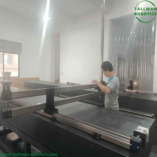


Motorized XYZ Linear Stages, XYZ three-axis linear motion platform is composed of three-axis linear modules, taking observation as the coordinate origin: the horizontal line realizing left and right linear motion is the X axis, the Y axis realizing front and rear linear motion, and Z axis realizing up and down linear motion. Z-axis is fixed on the X-axis linear module, and the Y-axis is fixed on the center of the platform; Z axis is called the operation axis or tool axis. In which industry the platform machine is used, what tools are installed on the Z axis; Y axis is the load axis, which carries the articles to be processed; X axis is positioned on the intersection point with the Y axis by moving left and right. What operations can XYZ three-axis linear motion platform(Motorized XYZ Linear Stages) achieve? Painting operation: painting operation is realized by three-axis movement fixed-point, and painting patterns and characters can be realized by accurate spraying in Y-axis point. Assembly: use the precise characteristics of the three-axis platform to assemble products, so as to reduce assembly time and improve production efficiency. Dispensing operation: precise dispensing and collecting operation is realized through three-axis fixed point. Soldering operation: similar to dispensing operation, it can be realized at fixed points. Screw locking operation: similar to glue dispensing operation, screw locking operation is realized at fixed points. Print job: use the sliding table to move at equal speed and distance to realize IC printing job. With the rapid development of automation, XYZ three-axis linear motion platform is more and more widely used. By installing or replacing tools in the Z-axis, and system programming, different application purposes can be achieved. Read the full article
#MiniatureStages#MotorizedMultiAxisStages#MotorizedxyzStage#Multi-AxisMotorized3-AxisStage#PositioningSystems#PrecisionLinearStage#PrecisionXYandXYZStages#XYZMotorizedTranslationStage#XYZPrecisionLinearStages#XYZ-Stages
0 notes