
Don't wanna be here? Send us removal request.
Statistics
We looked inside some of the posts by tallman-robotics and here's what we found interesting.
Average Info
Notes Per Post
1
Likes Per Post
1
Reblog Per Post
0
Reply Per Post
0
Time Between Posts
28 days
Number of Posts By Type
Text
16
Link
1
Last Seen Tumblr Blogs


Fun Fact
Tumblr posted its first advertisements in May 2012 and subsequently earned $13M in revenue.
Text
IP65 Waterproof XYZ Linear Modules Are Finished for UK Partners

IP65 Waterproof XYZ Linear Modules – Precision Motion for Harsh Environments! Dear client, Boost your automation reliability with our IP65-rated XYZ Linear Modules—engineered for dustproof and waterproof performance in demanding conditions. Perfect for food processing, automotive, and outdoor applications, they deliver ±0.01mm precision, corrosion resistance, and long-term durability. Reduce downtime and maintenance costs while ensuring consistent operation in wet or dusty environments. Interested? Request a quote or demo today! Contact me [email protected]! Also, you are welcome to visit our youtbue video gallery https://www.youtube.com/@tallmanrobotics


IP65 waterproof XYZ Linear Modules are ruggedized multi-axis motion systems designed for operation in harsh environments where dust, moisture, or liquid splashes are present. These modules maintain high precision in 3D positioning while offering enhanced protection against contaminants, making them ideal for industrial and outdoor applications. XYZ Linear Modules are an integrated linear motion system consisting of X, Y, and Z three-axis linear modules that are perpendicular to each other. It is driven by servo motors or stepper motors to achieve precise positioning and motion control in three-dimensional space. Its core components include guide rails, sliders, screw/belt transmission mechanisms, and control systems, typically designed in a modular manner to meet automation requirements.

IP65 Waterproof XYZ Linear Modules: Definition, Structure, Function, and Applications: Structure of IP65 Waterproof XYZ Linear Modules 1. Sealed Housing: Aluminum or stainless steel enclosures with IP65-rated seals to block dust and water ingress. 2. Protected Linear Components: Corrosion-resistant rails, sealed ball screws or belts, and waterproof motor connections. 3. Durable Drive System: Servo or stepper motors with IP65-rated connectors and cable glands. 4. Enhanced Bearings & Seals: Stainless steel or coated components to resist rust and wear. Structural composition of XYZ Linear Modules: 1. Mechanical frame: Aluminum alloy or steel structure, supporting three-axis motion units. 2. Drive shaft: Each shaft includes linear guides, ball screws (high precision) or synchronous belts (high speed), paired with motors (servo/stepper) and encoders. 3. Control System: PLC or motion control card, coordinating multi axis linkage, supporting G-code or specialized software programming. 4. End effector: Can be equipped with mechanical arms, suction cups, nozzles, and other tools. Functions of IP65 Waterproof XYZ Linear Modules Environmental Resistance: Withstands dust, humidity, and low-pressure water jets. High Precision & Load Capacity: Maintains ±0.02mm repeatability under harsh conditions. Longevity: Reduced maintenance due to sealed lubrication and anti-corrosion materials. Flexible Integration: Compatible with washdown environments (e.g., food processing). Applications of IP65 Dustproof XYZ System 1. Food & Beverage: Automated packaging in wet cleaning zones. 2. Automotive: Waterproof robotic welding and part handling. 3. Outdoor Machinery: Solar panel cleaning robots. 4. Marine & Chemical: Equipment requiring splash-proof motion control. Advantage of IP65 Waterproof XYZ Linear Modules : Reliable performance in demanding conditions, extending service life and reducing downtime. Read the full article
#Corrosion-resistantXYZlinearrails#Dustproof&waterproofXYZlinearguides#High-ingressXYZlinearmotionassemblies#Industrial-gradewaterproofXYZlinearsystems#IP65compliantXYZlinearstages#IP65enclosedXYZlineardriveunits#IP65protectedXYZlinearpositioningsystems#IP65-ratedXYZ-axislinearactuators#IP65-sealedXYZballscrewactuators#Outdoor-useXYZlinearmodules#SealedXYZ-axislinearslides#Splash-proofXYZlinearmotionmodules#WaterproofXYZlinearmotionsystems#WeatherproofXYZlineartranslationstages#XYZlinearmotiontableswithIP65sealing#XYZlinearsliderswithdust/waterprotection#XYZwaterprooflinearservoactuators#XYZ-axishermeticlinearactuators#XYZ-axisIP65-certifiedlineartransfersystems#XYZ-axiswater-resistantlinearmodules
0 notes
Text
High and low temperature planetary gearboxes will be delivered to Slovenia
A high and low temperature planetary gearbox is a specialized type of planetary gearbox designed to operate reliably under extreme temperature conditions, ranging from very low (e.g., -60°C or below) to very high (e.g., 200°C or above) temperatures. These gearboxes are used in industries where standard gearboxes would fail due to thermal expansion, material degradation, or lubrication issues. High and low temperature planetary gearboxes provide the reliability needed in such challenging environments. Key Features of High and Low Temperature Planetary Gearboxes 1. Specialized Materials Gear Components: Made from high-performance alloys (e.g., stainless steel, titanium, or heat-treated steels) to resist thermal deformation. Housing: Often aluminum alloy or stainless steel with thermal-resistant coatings. These materials are essential for planetary gearboxes operating at high and low temperatures. Bearings: Ceramic or high-temperature steel bearings to prevent failure under thermal stress. 2. High-Temperature Lubrication Synthetic lubricants (e.g., perfluoropolyether (PFPE) or silicone-based greases) that remain stable across a wide temperature range, crucial for high-low temperature planetary operations. Solid lubricants (e.g., graphite or molybdenum disulfide) for vacuum or ultra-high-temperature applications. 3. Thermal Management Heat-resistant seals to prevent lubricant leakage are important in maintaining planetary gearboxes under high and low temperature conditions. Thermal insulation or cooling systems (e.g., heat sinks or forced air cooling) for extreme environments. 4. Precision Engineering Tight tolerances to account for thermal expansion/contraction. Precision is key when engineering planetary gearboxes that withstand high and low temperatures. Optimized gear meshing to prevent binding or excessive wear. Applications Aerospace & Defense: Satellite mechanisms, drone actuators, missile systems. Oil & Gas: Downhole drilling equipment, high-temperature pumps. Industrial Automation: Furnace conveyors, steel mill machinery. Automotive: Electric vehicle (EV) drivetrains in extreme climates. These high and low temperature planetary gear reducers ensure effective operation across varied conditions. Scientific & Research: Cryogenic systems, space exploration rovers. Would you like recommendations for a specific application? You are welcome to watch more projects or visit our website to check other series or load down e-catalogues for further technical data. Youtube: https://www.youtube.com/@tallmanrobotics Facebook: https://www.facebook.com/tallmanrobotics Linkedin: https://www.linkedin.com/in/tallman-robotics Read the full article
#Backlash-FreePrecisionPlanetaryGearboxes#IndustrialPlanetaryGearboxes#PlanetaryGearBox#Planetarygeartransmissions#PlanetaryGearboxes#Planetarygearheadsformaximumtorque#PrecisionPlanetaryGearboxes
0 notes
Text
Intelligent Rotating Grippers Have Been Packed Well for Client from USA
Intelligent Rotating Grippers are Advanced End-of-Arm Tooling (EOAT) for Automation. Intelligent Rotating Grippers are advanced robotic end-effectors that combine gripping, rotation, and smart sensing capabilities for precision handling in industrial automation, assembly, and logistics. These grippers integrate servo-driven rotation, force feedback, and IoT connectivity for adaptive control in dynamic environments. Applications Industry Use Case Automotive Precision part insertion, screwdriving, wheel mounting. Electronics PCB handling, micro-component assembly. Pharmaceuticals Vial/pill sorting, lab automation. Logistics Parcel sorting, palletizing with orientation adjustment. Aerospace Composite material handling, turbine blade positioning. Comparison: Standard vs. Intelligent Rotating Grippers Feature Standard Gripper Intelligent Rotating Gripper Rotation Control Manual/Fixed angle Servo-driven, programmable Force Feedback None Real-time grip force adjustment Connectivity Standalone IoT-enabled (OPC UA, Ethernet/IP) Precision ±5° ±0.1° (with encoder feedback) Adaptability Fixed workflow AI-driven object recognition Future Trends: AI-Driven Gripping: Machine learning for self-adjusting grasp strategies. Human-Like Dexterity: Tendon-driven designs for complex manipulations. Energy Harvesting: Regenerative braking in servo motors for efficiency. You are welcome to watch more projects or visit our website to check other series or load down e-catalogues for further technical data. Youtube: https://www.youtube.com/@tallmanrobotics Facebook: https://www.facebook.com/tallmanrobotics Linkedin: https://www.linkedin.com/in/tallman-robotics Would you like details on a specific model or integration with robotic arms? Read the full article
#AdaptiveGripper#Durableroboticgripper#ElectricGrippers#ElectricRotaryGripperswithHigh-SpeedMotion#FullyActuatedHand#FullyActuatedRoboticHand#Grippersystem#MultiFingerGripper#ParallelGripper#Robotichand#RotaryElectricGrippers#Rotarygrippermanufacturers#RotatingServoGripperwithInfiniteRotation
0 notes
Text
Magnetic Levitation Circular Track Motor System
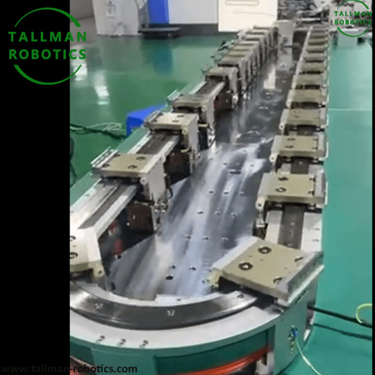
Magnetic Levitation Circular Track Motor System (MLCTMS) Introduction The Magnetic Levitation Circular Track Motor System (MLCTMS) is an advanced electromechanical system that combines magnetic levitation (maglev) and linear/rotary motor technology to enable frictionless, high-speed motion along a circular or curved track. Unlike conventional motors that rely on physical contact (e.g., bearings or gears), MLCTMS uses electromagnetic forces to levitate and propel objects, reducing wear, energy loss, and maintenance. https://www.youtube.com/embed/_uo-JyKC9rA Magnetic Levitation Circular Track Motor System has applications in transportation (maglev trains), industrial automation (high-precision conveyors), energy storage (flywheels), and amusement rides. Key Components 1. Track (Stator) - A circular or loop-shaped guideway embedded with electromagnetic coils (usually arranged as a linear synchronous motor, LSM). - Can be passive (permanent magnets) or active (electromagnets with control systems). 2. Levitation System - Uses repulsive or attractive magnetic forces to suspend the moving part (rotor/vehicle). - Common methods: - Electromagnetic Suspension (EMS) – Attracts ferromagnetic materials. - Electrodynamic Suspension (EDS) – Repels using superconducting magnets or eddy currents. 3. Propulsion System - Linear Induction Motor (LIM) or Linear Synchronous Motor (LSM) principles. - Coils in the track generate a traveling magnetic wave, pushing/pulling the rotor. 4. Control System - Ensures stable levitation and motion using sensors (gap sensors, Hall effect sensors) and feedback loops. - Adjusts current in electromagnets to maintain balance. How It Works 1. Levitation: - The system activates electromagnets to lift the rotor slightly above the track (typically 1–10 cm). - Sensors continuously monitor the gap and adjust magnetic force to prevent contact. 2. Propulsion: - A three-phase alternating current in the stator coils creates a moving magnetic field. - The rotor (equipped with permanent magnets or electromagnets) is either pushed (LSM) or induced (LIM) to move along the track. 3. Stabilization: - Active control systems counteract disturbances (vibrations, external forces). - Some designs use Halbach arrays to enhance magnetic field efficiency. Advantages of Magnetic Levitation Circular Track Motor System Near-zero friction → Higher efficiency & longer lifespan. Low maintenance (no mechanical wear). High-speed operation (useful for maglev trains, centrifuges). Precision control (useful in semiconductor manufacturing, lab automation). Reduced noise & vibration. Applications Transportation:Maglev trains, hyperloop systems. Industrial Automation: High-speed conveyors, robotic arms. Energy Storage: Flywheel energy storage (frictionless rotation). Amusement Rides:Floating roller coasters. Scientific Research: Centrifuges, space simulation (microgravity effects). Future Developments Superconducting magnets for more efficient levitation. Modular & scalable designs for cost reduction. Integration with renewable energy (solar/wind-powered maglev systems). Conclusion of Magnetic Levitation Circular Track Motor System The Magnetic Levitation Circular Track Motor Systemrepresents a cutting-edge fusion of electromagnetics and motion control, enabling ultra-efficient, high-speed, and maintenance-free operation. While challenges like cost and energy use remain, advancements in materials and control algorithms continue to expand its potential across industries. You are welcome to watch more projects or visit our website to check other series or load down e-catalogues for further technical data. Youtube: https://www.youtube.com/@tallmanrobotics Facebook: https://www.facebook.com/tallmanrobotics Linkedin: https://www.linkedin.com/in/tallman-robotics Read the full article
#maglevtestcirculartracksystem#Magneticlevitation#MagneticLevitationforFreedom#Magneticlevitationplanarmotor
1 note
·
View note
Text
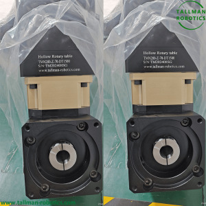
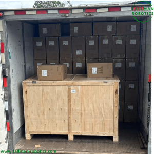
Precise Positioning Hollow Rotary Tables Will Be Delivered to Pakistan

Precise Positioning Hollow Rotary Tables are specialized rotational devices featuring a central hollow shaft, designed for high-accuracy angular positioning. The hollow core allows cables, pneumatic lines, or shafts to pass through, eliminating cable tangling and reducing system complexity.
https://youtu.be/ZP31od3m6Xc?si=KSzfpuXjjSW-2xnV Key Components and Features 1. Drive Mechanisms: Harmonic Drives: Preferred for near-zero backlash and high torque density. Direct Drive Motors: Offer smooth operation and precise control without mechanical reduction. Alternative systems like worm gears may be used but are less common in ultra-high-precision settings. 2. Bearings: Crossed Roller Bearings: Provide high rigidity and accuracy, handling both radial and axial loads efficiently. 3. Feedback Systems: High-resolution absolute encoders ensure accurate position tracking, even after power interruptions. 4. Materials and Construction: Made from rigid materials like aluminum or steel alloys to minimize deflection under load. Standardized mounting interfaces (e.g., ISO/SAE flanges) for easy integration with machinery. Applications of Large hollow shaft rotary tables CNC Machining: Enables multi-axis machining by rotating workpieces precisely. Semiconductor Manufacturing: Used in wafer handling and inspection systems. Optics and Medical Devices: Positions lenses or surgical tools with high accuracy. Robotics: Facilitates precise joint movements in automation and articulated robots. Advantages Over Standard Rotary Tables Hollow Design: Central pass-through avoids cable management issues, enhancing reliability. High Precision: Sub-arc-minute accuracy achievable with advanced feedback and drive systems. Versatility: Suitable for diverse industries due to customizable sizes and load capacities. Conclusion Precise Positioning Hollow Rotary Tables/Large hollow shaft rotary tables are critical in applications demanding exact angular positioning with central component pass-through. Their design combines mechanical precision with intelligent feedback systems, making them indispensable in advanced manufacturing and automation. You are welcome to watch more projects or visit our website to check other series or load down e-catalogues for further technical data. Youtube: https://www.youtube.com/@tallmanrobotics Facebook: https://www.facebook.com/tallmanrobotics Linkedin: https://www.linkedin.com/in/tallman-robotics Read the full article
#CNCHollowRotaryActuator#HeavyDutyHollowRotaryTables#HighPrecisionHollowRotaryTablesforCNCMachines#High-precisionrotarytable#HollowAxes#HollowRotaryPlatform#HollowRotaryTableRightAngleManufacturer#LargeApertureHollowRotaryTables#Largehollowshaftrotarytables#PlanetaryGearboxes#PrecisePositioningHollowRotaryTables#PrecisionHollowRotaryTable#PrecisionRightAngleRotaryTables#RotaryActuators
0 notes
Text
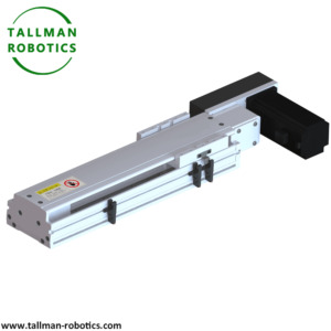
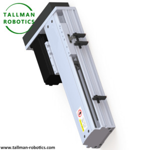
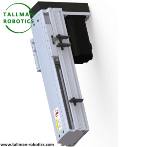
Stroke Adjustable Linear Module

Stroke adjustable linear modules are mechanical devices used in automation and machinery to provide linear motion. The term "stroke adjustable" refers to the ability to change or adjust the length of the linear movement (stroke) that the module can perform. This adjustability is crucial in applications where the required travel distance may vary or need to be precisely set for different tasks. Key Features of Stroke Adjustable Linear Modules: 1. Adjustable Stroke Length: The primary feature is the ability to adjust the stroke length, which can be done manually or automatically depending on the design. This allows for flexibility in positioning and movement. 2. Linear Motion: These modules convert rotary motion (from a motor) into linear motion, typically using a lead screw, ball screw, or belt drive mechanism. 3. Precision and Accuracy: They are designed to provide precise and accurate linear movement, which is essential in applications like CNC machines, 3D printers, and robotic arms. 4. Load Capacity: They can be designed to handle various load capacities, from light-duty applications to heavy-duty industrial tasks. 5. Mounting Options: These modules often come with multiple mounting options, making them versatile for different installation requirements. 6. Integration with Control Systems: They can be integrated with various control systems, including PLCs (Programmable Logic Controllers) and CNC systems, for automated control of the stroke length and position. Technical Parameters Items TMSA60 TMSA70 TMSA80 TMSA80F TMSA100 TMSA120 TMSA175 TMSA210 Slide width(mm) 8/10/20/25 20/25/30 10/12/15/20/25/30 10/12/15 24/30 15/20/25/30/40 45/60/100/120 45/60/100/120 Minimum distribution distance(mm) 8.5mm 20mm 10mm 10mm 24mm 15mm 10mm 45mm Slide quantity(pcs) >2 >2 >2 >2 >2 >2 >2 >2 Repeatability accuracy(mm) ±0.02 mm ±0.02 mm ±0.02 mm ±0.02 mm ±0.02 mm ±0.02 mm ±0.02 mm ±0.02 mm Positioning accuracy(mm) ±0.05 mm ±0.05 mm ±0.05 mm ±0.05 mm ±0.05 mm ±0.05 mm ±0.05 mm ±0.05 mm Distribution distance accuracy(mm) ±0.1 mm ±0.1 mm ±0.1 mm ±0.1 mm ±0.1 mm ±0.1 mm ±0.1 mm ±0.1 mm Input torque(N.m) Above 0.3 Above 1.3 Above 1.3 Above 1.3 Above 1.3 Above 1.3 Above 3.2 Above 3.2 Driving solution 42 stepper motor/ 100W servo motor 57 Stepper Motor/ 200W/400W Servo Motor 57 Stepper Motor, 200W/400W Servo Motor 57 Stepper Motor, 200W/400W Servo Motor 57 stepper motor 200W/400W servo motor +gear reducer 86 stepper motor 200W/400W/750W servo motor +gear reducer 86 stepper motor 750W servo motor +gear reducer 86 stepper motor 750W servo motor +gear reducer Maximum Sliding frequency 120 cpm 120 cpm 120 cpm 120 cpm 120 cpm 120 cpm 120 cpm 120 cpm

Applications of Stroke Adjustable Linear Modules: Automation Systems: Used in automated assembly lines, packaging machines, and material handling systems. Robotics: Integral components in robotic arms and other robotic systems where precise linear movement is required. CNC Machinery: Employed in CNC routers, mills, and lathes for precise tool positioning. Medical Devices: Utilized in medical imaging systems, surgical robots, and diagnostic equipment. 3D Printing: Essential in 3D printers for controlling the movement of the print head or build platform. Types of Stroke Adjustable Linear Modules: 1. Motorized Linear Modules: Equipped with a motor (stepper, servo, or DC motor) for automated control of the stroke length. 2. Manual Linear Modules: Adjusted manually, often used in applications where the stroke length does not need to change frequently. 3. Belt-Driven Linear Modules: Use a belt and pulley system for smooth and high-speed linear motion. 4. Screw-Driven Linear Modules: Utilize a lead screw or ball screw for precise and high-force linear motion. Advantages of Stroke Adjustable Linear Modules: Flexibility: The ability to adjust the stroke length makes these modules highly versatile. Precision: Provides accurate and repeatable linear motion. Ease of Integration: Can be easily integrated into existing systems and controlled via various means. Durability: Designed to withstand rigorous use in industrial environments. In summary, stroke adjustable linear modules are essential components in many automated systems, offering the flexibility of adjustable stroke lengths along with precise and reliable linear motion. You are welcome to watch more projects or visit our website to check other series or load down e-catalogues for further technical data. Youtube: https://www.youtube.com/@tallmanrobotics Facebook: https://www.facebook.com/tallmanrobotics Linkedin: https://www.linkedin.com/in/tallman-robotics Read the full article
#AdjustableStrokeLinearActuator#AdjustableStrokeLinearActuators#Automotivelinearactuator#ElectricAdjustableStrokeIndustrialLinearActuator#LinearActuatorwithadjustablelimitswitches#linearactuatorwithadjustablestroke
0 notes
Text
Dual Lead Worm Gear Hollow Rotary Tables

Dual Lead Worm Gear Hollow Rotary Tables are constructed with two leads. One flank of the worm thread and its mating sides of the wheel teeth are manufactured with one lead, and the other flank and its mating wheel teeth to a slightly different lead. Dual Lead Worm Gear Hollow Rotary Tables have higher features by 1 arc minute, Adjustable backlash! ● Grinding gear design, can bear higher moment of inertia and impact force ● High rigidity, high load, output integrated cross roller bearing ● Adopting a dual lead worm structure with adjustable backlash Model Selection code of Dual Lead Worm Gear Hollow Rotary Tables:

Technical Parameters of Dual Lead Worm Gear Hollow Rotary Platforms: Specification TMDL-60 TMDL-85 TMDL-130 TMDL-200 TMDL280 Reduction ratio 30/60/90 10.25/30/60/90 10.25/30/60/90 10.25/30/60/90 30/60/90 Admissible thrust load (Kgs) 50 60 160 250 480 Bearings High rigidity, high load, output integrated cross roller bearing Lifespan (Hours) 20000 positioning accuracy (arc-min) ≤1′ ≤1′ ≤1′ ≤1′ ≤1′ Rotation platform plane jumping (mm) ≤0.01 ≤0.01 ≤0.01 ≤0.01 ≤0.01 Rotation platform radial runout (mm) ≤0.01 ≤0.01 ≤0.01 ≤0.01 ≤0.01 Protection class(IP) IP40 IP40 IP40 IP40 IP40 Weight(kgs) 1.0kgs 2.5kgs 5.5kgs 15kgs 45kgs Servo motor/Stepper 42 Servo motor/42 stepper 60 Servo motor/57 stepper 60 Servo motor/57 stepper 80 Servo motor/86 stepper 130 Servo motor Options Driver and Cable Driver and cable provided if Motor provided by Tallman Robotics Limited (Usually, we configure Delta, Inovance ) Face rotating Plate Provided if needed.(Drawing provided by the clients) Sensors Photoelectric sensor, brackets, sensor plates, screws are for options. You are welcome to watch more projects or visit our website to check other series or load down e-catalogues for further technical data. Youtube: https://www.youtube.com/@tallmanrobotics Facebook: https://www.facebook.com/tallmanrobotics Linkedin: https://www.linkedin.com/in/tallman-robotics Production of Dual Lead Hollow Rotary Tables:


Read the full article
#DoubleLeadWormGearHolllowrotaryActuators#DoubleLeadWormGearHolllowrotaryPlatforms#DoubleLeadWormGearHolllowrotarytables#DoubleLeadWormGearreducers#DoubleLeadWormGears#DualLeadWormGear#DualLeadWormGearreducers#DualLeadWormGears
0 notes
Text
Dual Lead Worm Reducers

Dual lead worm reducers, also known simply as dual worm reducers or dual lead gearboxes, are mechanical devices used to reduce the speed of an input shaft while increasing torque. Dual lead worm reducers work on the principle of converting rotational motion and torque from an input shaft to a slower rotational motion and higher torque at the output shaft using a pair of helical threads arranged on the worm.They are commonly employed in various applications, such as conveyors, robotics, and other machinery where high torque and low-speed output are required. Key Features of Dual Lead Worm Gear Reducers: Worm Gear Configuration: Dual lead worm reducers utilize a worm gear mechanism, where a screw (the worm) drives a wheel (the worm gear). This arrangement allows for high torque multiplication. Dual Lead Design: The term "dual lead" refers to the use of two threads (or leads) on the worm. This design allows for greater efficiency, as it results in a smoother motion and reduces the friction compared to single lead designs. It also enables a faster gear ratio in a compact size. High Torque: These reducers provide significant torque output, making them suitable for heavy-duty applications. Compact Size: The compact housing of dual lead worm reducers allows them to be used in applications with space restrictions. Self-Locking Properties: One of the advantages of worm gear mechanisms is that they often allow for self-locking. This means that the output cannot drive the input when at rest, which can provide an added level of safety in some applications. Output Direction: The orientation of the worm gear can change the direction of the output shaft, making it versatile for different applications and designs. Applications: Conveyor Systems: Used in material handling to reduce speed and increase the torque of conveyor belts. Robotics: Commonly found in robotic joints and actuators for controlled movement. Industrial Machinery: Employed in various machines that require speed reduction and increased force. Automotive Applications: Sometimes used in steering mechanisms or winches where control and torque are priorities Model Selection code of Double Lead Worm Gear Reducers:


Technical Parameters of Double Lead Worm Gear Reducers:


You are welcome to watch more projects or visit our website to check other series or load down e-catalogues for further technical data. Youtube: https://www.youtube.com/@tallmanrobotics Facebook: https://www.facebook.com/tallmanrobotics Linkedin: https://www.linkedin.com/in/tallman-robotics Read the full article
#DoubleLeadWormGearHolllowrotaryActuators#DoubleLeadWormGearHolllowrotaryPlatforms#DoubleLeadWormGearHolllowrotarytables#DoubleLeadWormGearHollowRotaryActuators#DoubleLeadWormGearreducers#DoubleLeadWormGears#DoubleWormGearReducers#DoubleWormGears#DualLeadWormGear#DualLeadWormGearreducers#DualLeadWormGears
0 notes
Text
Double Lead Worm Gear Hollow Rotary Tables

Double lead worm gear hollow rotary tables are specialized mechanical devices used in various applications, particularly in machining and automation. They combine the features of a worm gear with a hollow design, allowing for efficient rotation and positioning of objects or tools while providing an open center that can accommodate other components, such as shafts or cables. Key Features of Double Lead Worm Gear Hollow Rotary Platforms: 1 arc minute,adjustable backlash ●Grinding gear design, can bear higher moment of inertia and impact force ●Adopting a dual lead worm structure with adjustable backlash ●High rigidity, high load, output integrated cross roller bearing A double lead worm gear has two starts, allowing for faster rotation and greater positional accuracy compared to single lead designs.The gear mechanism converts rotational motion into linear motion and provides a high gear reduction ratio, which helps in achieving precise control over the angular movement. Hollow Design: The hollow feature provides an unobstructed passage through the center of the table, which is useful for applications where routing of other components (like coolants, sensors, or materials) is necessary. This design also helps in reducing the overall weight and can lead to simplified setup in automated systems. Rotary Motion: These tables enable precise rotary motion, making them suitable for tasks like CNC machining, indexing, and assembly processes. They are often used in applications needing high precision, such as aerospace, automotive, and medical device manufacturing. Load Capacity: These rotary tables are engineered to support varying loads and can be designed to handle heavy components without compromising the precision of the movement. Applications: Used in combinations with CNC machines for intricate fabrications. Integrated into robotic arms for improved flexibility. Employed in positioning systems for laser cutting and engraving. Model Selection code of Double Lead Worm Gear Hollow Rotary Tables:

Technical Parameters of Double Lead Worm Gear Hollow Rotary Platforms: Specification TMDL-60 TMDL-85 TMDL-130 TMDL-200 TMDL280 Reduction ratio 30/60/90 10.25/30/60/90 10.25/30/60/90 10.25/30/60/90 30/60/90 Admissible thrust load (Kgs) 50 60 160 250 480 Bearings High rigidity, high load, output integrated cross roller bearing Lifespan (Hours) 20000 positioning accuracy (arc-min) ≤1′ ≤1′ ≤1′ ≤1′ ≤1′ Rotation platform plane jumping (mm) ≤0.01 ≤0.01 ≤0.01 ≤0.01 ≤0.01 Rotation platform radial runout (mm) ≤0.01 ≤0.01 ≤0.01 ≤0.01 ≤0.01 Protection class(IP) IP40 IP40 IP40 IP40 IP40 Weight(kgs) 1.0kgs 2.5kgs 5.5kgs 15kgs 45kgs Servo motor/Stepper 42 Servo motor/42 stepper 60 Servo motor/57 stepper 60 Servo motor/57 stepper 80 Servo motor/86 stepper 130 Servo motor Options Driver and Cable Driver and cable provided if Motor provided by Tallman Robotics Limited (Usually, we configure Delta, Inovance ) Face rotating Plate Provided if needed.(Drawing provided by the clients) Sensors Photoelectric sensor, brackets, sensor plates, screws are for options. You are welcome to watch more projects or visit our website to check other series or load down e-catalogues for further technical data. Youtube: https://www.youtube.com/@tallmanrobotics Facebook: https://www.facebook.com/tallmanrobotics Linkedin: https://www.linkedin.com/in/tallman-robotics Production of Cam Roller Hollow Rotary Tables:


Read the full article
#HollowOutputshaftDoubleLead#Rotaryindexingtablesdrivenbydoubleleadwormgear#Rotarytableswithwormgeardrive#Wormgearrotarytables
0 notes
Link
#FullyProtectedRoboticArms#HighSpeedLongStrokeDoubleShaft#Linearrobotwithextra-longstroke#LongStrokeHighSpeedHeavy-DutyLinearModule#LongStrokeLinearActuator#LongStrokeLinearModules#LongStrokeLinearMotion
0 notes
Text
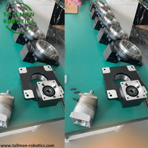
Hollow Rotary Indexing Actuators Ready for Client from Singapore

Hollow Rotary Indexing Actuators typically consist of a hollow shaft through which various operations can be performed, such as clamping, rotating, or presenting components for assembly or processing. This design allows for the passage of materials, tools, or other components through the center of the actuator, enabling seamless integration into an automated production line. Hollow rotary indexing actuators are mechanical devices used to accurately position objects or components in a rotational manner. They are commonly employed in automated manufacturing and assembly systems, where precise indexing and positioning are crucial. Hollow rotary indexing actuators can be found in a variety of industries including automotive, electronics, packaging, and more, where they play a critical role in increasing productivity and efficiency in manufacturing processes. They are often used in conjunction with other automated equipment to create seamless production lines capable of performing complex operations with precision.
The typical components of hollow rotary indexing actuators may include: Hollow Shaft: The central component through which materials, tools, or components can pass. This feature allows for seamless integration into automated production lines and facilitates the passage of materials or tools through the center of the actuator. Indexing Mechanism: This is a key component that allows for precise indexing or positioning of the actuator. It controls the rotational movement of the actuator, ensuring accurate positioning for various manufacturing or assembly processes. Clamping Mechanism: Some hollow rotary indexing actuators feature a clamping mechanism that secures components in place during indexing or processing. This helps to maintain the stability and precision of the positioning operations. Drive System: This can include motors, gears, or other mechanisms that provide the rotational force necessary to drive the indexing movement of the actuator. Control System: Typically, these actuators are equipped with control systems that manage the indexing movements, timing, and coordination with other elements within the production line. Support Structure: The actuator is often mounted on a support structure that allows for integration into the production line and provides stability during operation. These components work together to enable the precise and reliable indexing and positioning of components in manufacturing and assembly applications. Keep in mind that the specific components can vary based on the manufacturer and the intended application of the hollow rotary indexing actuator. You are welcome to watch more projects or visit our website to check other series or load down e-catalogues for further technical data. Youtube: https://www.youtube.com/@tallmanrobotics Facebook: https://www.facebook.com/tallmanrobotics Linkedin: https://www.linkedin.com/in/tallman-robotics Read the full article
#HollowRotaryActuatortable#hollowrotaryactuators#HollowRotaryIndexingActuators#HollowRotaryTables#RotaryActuators#RotaryJoints
0 notes
Text
Linear Motion Solutions

Linear motion solutions refer to the various technologies and systems designed to provide controlled, precise linear movement. These solutions are used across a wide range of industries and applications, including industrial automation, robotics, machinery, and more.
Here are some key aspects of linear motion solutions:
Types of Linear Motion Systems: Ball screw systems,Lead screw systems,Linear motor systems,Belt-driven systems,Air/fluid bearing systems,Rack and pinion systems,Linear slide systems Key Components:, Linear actuators (e.g. ball screws, lead screws, linear motors),Linear guides (e.g. linear bearings, rails, slides),Drive mechanisms (e.g. stepper motors, servo motors),Control systems (e.g. motion controllers, drivers),Feedback sensors (e.g. encoders, limit switches) Design Considerations: Application requirements (e.g. load, speed, precision),Environmental factors (e.g. temperature, humidity, contaminants),Space constraints and mounting configurations,Integration with other systems and equipment,Maintenance and lubrication needs Common Applications: Industrial automation and robotics,CNC machines and machine tools,Semiconductor manufacturing equipment,Packaging and material handling systems,Medical devices and instrumentation,Test and measurement equipment,3D printing and additive manufacturing Trends and Advancements:,Increased use of linear motors for high-speed, high-accuracy applications,Integration of smart sensors and Industry 4.0 connectivity,Advancements in control algorithms and software,Developments in materials and lubrication for improved performance and reliability


You are welcome to watch more projects or visit our website to check other series or load down e-catalogues for further technical data. Youtube: https://www.youtube.com/@tallmanrobotics Facebook: https://www.facebook.com/tallmanrobotics Linkedin: https://www.linkedin.com/in/tallman-robotics Read the full article
#Linearbearingsandshafts#LinearGuides#LinearMotionBearings#LinearMotionComponents#Linearmotionsolutionsandapplications#LinearMotionStages#Linearmotionsystems#linearslidesandpositioningsystems#LinearXYStages#MotionControlSystem#Top-QualityLinearMotionSupplies
0 notes
Text
Linear Actuators Robots

Linear Actuators Robots are a pivotal technology in modern robotics due to their versatility, precision, and scalability. They have a broad range of applications in various fields. Here's an overview of how Linear Actuators Robots are integrated into robotic systems and their benefits: Classification and Mechanisms: Types: Linear Actuators Robots can be driven by different mechanisms including screw type, belt drives, and linear motors. Each mechanism offers unique advantages; for instance, screw-based actuators driven by stepping motors are highly suitable for precise positioning but may be underpowered for certain applications requiring servo motors. Motion and Force: These actuators provide both horizontal and vertical motion. They can handle travel distances up to 500 feet and speeds up to 600 inches per second, and manage loads up to 10,000 pounds, making them suitable for a variety of industrial applications. Applications: Manufacturing Automation: Linear Actuators Robots are prominently used in automation for repetitive, tedious, or dangerous tasks. They help in streamlining processes and maintaining high precision and consistency in manufacturing, greatly reducing production costs. Prosthetics: The introduction of micro linear actuators has revolutionized prosthetics, enabling more natural and powerful motions in prosthetic hands. These tiny actuators offer significant strength and precision, essential for driving individual fingers directly. Drones and Aerospace: In drones, actuators are used for functions such as camera gimbals, retractable landing gear, and arms for manipulating objects. They are also incorporated into aerospace applications, such as the International Space Station, demonstrating their reliability and precision in high-stakes environments. In conclusion, Linear Actuators Robots are vital components in the development of robotic systems, offering a broad spectrum of applications from industrial automation to advanced prosthetics and space exploration. Their adaptability, precision, and robustness make them indispensable in advancing robotics technology into the future. Here, we introduce our Screw drive linear modules by model TMS45 semi-closed type for general environment.


You are welcome to watch more projects or visit our website to check other series or load down e-catalogues for further technical data. Youtube: https://www.youtube.com/@tallmanrobotics Facebook: https://www.facebook.com/tallmanrobotics Linkedin: https://www.linkedin.com/in/tallman-robotics Read the full article
#ActuatorsinCartesianRobot#AutomationandRoboticswithElectricLinearActuator#Cartesianrobotic#Electriclinearactuators#IndustrialRobotslinearactuators#inearActuators#LinearActuator#Linearactuatorrobots#LinearActuatorsforRobotics#LinearMotionandActuatorsforSurgicalRobotics#Linearmotorsingleaxisrobots#LinearMotors&Actuators#Linearrobots#MicroLinearActuators#MultiStationBeltLinearActuator2AxisRobot#PrecisionLinearActuators#RobotActuators#RobotLinearActuators#RoboticArmwithLinearActuators#roboticslinearactuator#SingleAxisRobotLinearActuators#SingleAxisRobots#XYActuator(SingleRail)
0 notes
Text
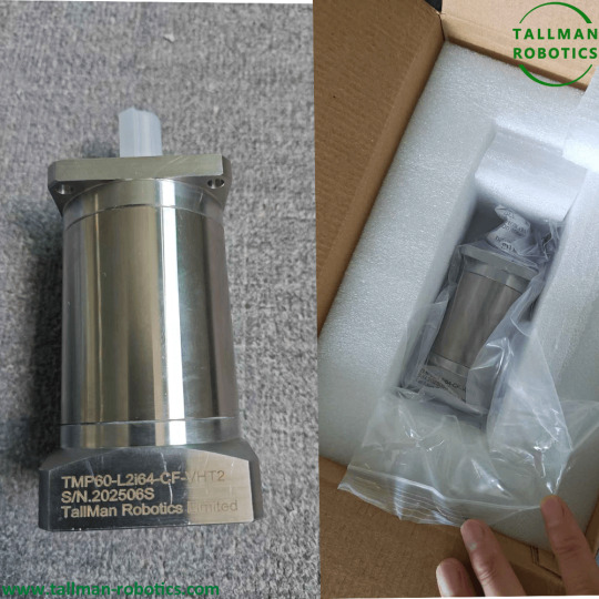
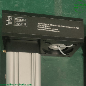
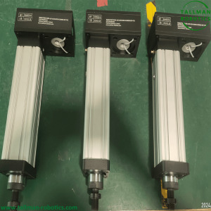
Servo Electric Cylinders Will Be Sent To USA

Servo Electric Cylinders from Tallman Robotics are ready to Be Sent To USA Servo Electric Cylinders are electromechanical devices that convert electrical energy into linear motion. They consist of a motor, gears, and a piston or rod that extends and retracts along a linear axis. These cylinders are commonly used in various applications where linear force or displacement is required. The main feature of Servo Electric Cylinders is their ability to provide precise and controlled linear movement. They can be programmed to move to specific positions, with adjustable speed and force. This makes them suitable for tasks such as automated machinery, industrial processes, and robotics.


Introduction to the application scenarios of Servo Electric Cylinders: Servo Electric Cylinders are widely used and suitable for many different fields. In addition to the automotive, medical, and industrial sectors mentioned earlier, they are also commonly used in the following scenarios: In the aerospace field, linear actuator electric cylinders are used for aircraft seat adjustment, cabin door opening and closing, and instrument panel control. In stage equipment, they can achieve the movement and lifting of stage scenery. In building automation systems, it is used to control windows, sunshades, and access control systems. In addition,Servo Electric Cylinders are also used in office furniture, such as adjustable height desks and electric seats. In agricultural machinery, they can control the cutting height of the harvester or the nozzle position of the irrigation system. In laboratory equipment, it is used for sample transfer and precise operation of experimental instruments. These are just some common application scenarios, in fact, their application scope also includes many fields such as robotics technology, military equipment, entertainment facilities, etc. Their precise control and reliable performance make them play an important role in various devices and systems that require linear motion. With the continuous development of technology, the application prospects of linear actuator electric cylinders will be even broader. You are welcome to watch more projects or visit our website to check other series or load down e-catalogues for further technical data. Youtube: https://www.youtube.com/@tallmanrobotics Facebook: https://www.facebook.com/tallmanrobotics Linkedin: https://www.linkedin.com/in/tallman-robotics Read the full article
#ChinaServoElectricCylinderManufacturers#ElectricCylinderActuators#electriccylinderswithmotorandServodrive#HighForceElectricLinearActuator#IP65ServoElectricCylinders#LinearServoElectricActuators#ServoElectricLinearActuators#ServoMotorElectricCylinder#SmartServoCylinders
0 notes
Text
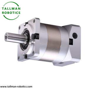
-196°C-+200°C Cryogenic Planetary Gear Reducers

Cryogenic Planetary Gear Reducers are special type of gear reducers designed to operate in extremely low temperature environments. It combines advanced cryogenic technology with the principles of planetary gears to achieve efficient power transmission and reduction.
Cryogenic Planetary Gear Reducers from Tallman Robotics Limited can work well in temperature -196℃-+200℃.
This Cryogenic Planetary Gear Reducer is typically used in applications that require operating in cryogenic conditions, such as in aerospace, scientific research, or industrial fields. The cryogenic environment may involve temperatures as low as -196°C or even lower.

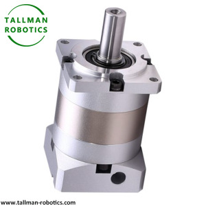
The key features of the Cryogenic Planetary Gear Reducers include: 1. Special materials: It employs high-strength materials that can withstand the extreme cold without undergoing significant deformation or failure. 2. Insulation and sealing: Excellent insulation and sealing mechanisms are incorporated to prevent heat leakage and ensure the integrity of the cryogenic system. 3. Precision gears: The planetary gear design provides precise gear alignment and transmission, allowing for efficient power reduction with minimal power loss. 4. Lubrication: Special lubricants are used to ensure smooth operation and reduce friction in the cryogenic environment. 5. Robust construction: It is built to withstand the rigors of cryogenic conditions, including temperature fluctuations and exposure to low temperatures. Overall, Cryogenic Planetary Gear Reducers play a critical role in enabling machinery and systems to function reliably and efficiently in extreme low-temperature environments, where conventional gear reducers may not be suitable. Its advanced design and materials make it an essential component in various cryogenic applications. You are welcome to watch more projects or visit our website to check other series or load down e-catalogues for further technical data. Youtube: https://www.youtube.com/@tallmanrobotics Facebook: https://www.facebook.com/tallmanrobotics Linkedin: https://www.linkedin.com/in/tallman-robotics Read the full article
#-196℃-+200℃Planetaryreducers#cryogenicequipment#Cryogeniclinearactuator#cryogenicPlanetaryGearReducers#CryogenicSystemServices#HighQualityGearReducer#LowTemperatureReducer#PlanetaryGearboxManufacturer#Planetarygearboxsystem
0 notes
Text
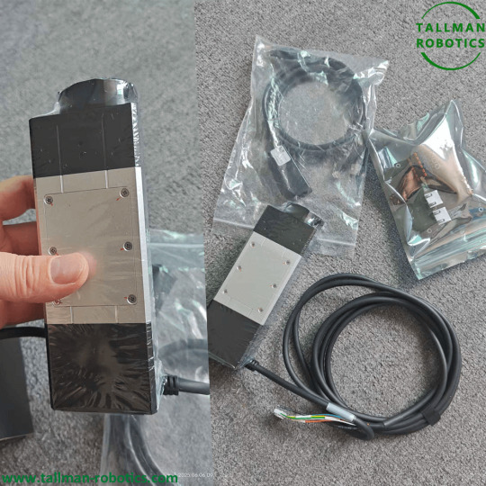
IP65 Waterproof Electric Gripper
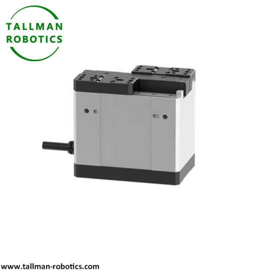
This IP65 Waterproof Electric Gripper is a high-performance device designed to handle challenging environments with ease. With its robust construction and advanced waterproofing capabilities, this IP65 Waterproof Electric Gripper offers reliable and precise gripping functionality in various industries.
In terms of waterproofing, IP65 rating indicates that the gripper has good dust-proof and waterproof performance.
This is usually achieved through sealing design and protective measures to prevent dust and water from entering the interior of the gripper. To ensure waterproof performance, the outer shell of the gripper usually adopts a sealed structure, which may include sealing rings, gaskets, or other sealing components. These sealing measures can prevent water and dust from entering the internal electronic and mechanical components of the gripper IP65 Waterproof Electric Gripper is engineered to withstand exposure to water, dust, and other elements, making it suitable for outdoor and industrial applications. The IP65 rating ensures that it provides protection against ingress of both solid particles and low-pressure water jets, allowing it to operate reliably in wet or dusty conditions. Featuring electric actuation, IP65 Waterproof Electric Gripper offers precise control and positioning, enabling accurate handling of objects. It can be seamlessly integrated into automated systems, enhancing productivity and efficiency. The waterproof design eliminates the need for additional enclosures or protection, reducing complexity and costs. Whether used in manufacturing, robotics, automotive, or any other industry that requires rugged and waterproof grippers, IP65 Waterproof Electric Gripper delivers consistent performance and durability. It offers a reliable solution for handling objects in harsh environments, ensuring smooth and efficient operations. With its compact size and versatile design, it can adapt to different setups and applications, providing a flexible and efficient gripping solution. Items Technical Parameters Product code TM-MFGB-08-80-1-D0300-ITG Size code 08 Stroke(mm) 80 Max clamping force 150N Max payload(kg) 3 Maxs speed open/close 0.7/0.7(s) Allowable load(Nm) MR:5.5 , MP:3.7 , MY:3.1 Positioning repeatability ±0.03(mm) Weight(kg) 1 Control method Bus Communication protocol Modbus RTU Rated voltage(V) DC24±10% Rated current(A) 4 Ambient environment 0 ~ 40℃,85%RH ( below ) IP rating IP65/IP55 In addition to industrial and outdoor applications, IP65 waterproof electric grippers can also be widely used in the following fields: 1. Medical Equipment: In the medical industry, this IP65 Waterproof Electric Gripper can be used for the operation of medical equipment, such as surgical robots, laboratory automation equipment, etc., to ensure accurate clamping and operation in clean and humid environments. 2. Food processing: The food processing field requires frequent cleaning of equipment. The IP65 waterproof electric gripper is suitable for food processing and packaging machinery, and can work stably in humid production environments. 3. Oceans and Ships: The waterproof requirements for equipment in the field of ships and oceans are very high, and this clamp can be used for marine exploration equipment, ship automation systems, etc. 4. Laboratory and scientific research: In scientific research laboratories, IP65 Waterproof Electric Gripper may need to come into contact with various liquids or operate in humid environments, and its IP65 waterproof characteristics make it suitable for such applications. 5. Automotive and Transportation: During the manufacturing and maintenance process of automobiles, grippers can be used to grip and operate components, especially in work involving water washing or humid areas. 6. Agriculture and Horticulture: Agricultural and horticultural equipment is often exposed to outdoor environments, and grippers can be used for automated irrigation systems, agricultural product harvesting machinery, etc. 7. Energy and Power: In the energy and power industry, such as the maintenance of wind turbines and solar equipment, waterproof clamps can be used to clamp and operate components. 8. Underwater robots: Underwater robots require waterproof clamping devices to perform various tasks, such as sampling and detection. 9. Electronic Equipment Manufacturing: In the electronic manufacturing process,IP65 Waterproof Electric Gripper can be used to clamp and assemble sensitive electronic components, and their waterproof characteristics help prevent component damage. These are just some possible application areas. In fact, the applicability of IP65 waterproof electric grippers can be extended to more fields according to specific needs and innovative applications. Its waterproof performance and electric driving method give it great advantages in clamping operations that require water resistance, moisture resistance, or special environmental conditions. You are welcome to watch more projects or visit our website to check other series or load down e-catalogues for further technical data. Youtube: https://www.youtube.com/@tallmanrobotics Facebook: https://www.facebook.com/tallmanrobotics Linkedin: https://www.linkedin.com/in/tallman-robotics Read the full article
#Electricactuator2-fingerGripper#IP65DustProofElectricGripper#IP65DustproofElectricGrippers#IP65OutdoorWaterproofElectricalGripper#IP67WaterproofElectricGrippers#LongStrokeElectricGripper#WaterResistantElectricGrippers
0 notes
Text
IP67 Waterproof Electric Grippers

IP67 waterproof electric grippers are designed to withstand exposure to water and moisture, making them suitable for use in moisture or dusty environments. IP67 Waterproof Electric Grippers refer to a type of gripper mechanism that is designed to meet the IP67 rating for environmental protection. The IP67 rating indicates that the gripper is highly resistant to dust and water ingress, making it suitable for use in harsh or challenging environments.
Features of IP67 waterproof electric grippers, IP67 dust proof electric grippers from Tallman Robotics Limited have unique characteristics as follows:
IP67 protection level Waterproof, dustproof, corrosion-resistant, and debris resistant Quick opening and closing Stable and reliable


Model No. TM-GBTD-11-40-10-ITG Size code 11 Stroke(mm) 40 Max clamping force 1(N) 45 Max speed(mm/s) 250 Repeatability(mm) ±0.02 Fastest opening/closing time(s) 0.3/0.3 Back lash(mm) Below 0.1on single side Allowable load torque(N.m) MR:2.5,MP:2.5,MY:3 Controller Built-in Control solution-BUS ModbusRTU Control solution-Interface I/O Control I/O interface Input3points(NPN),output 3 points(NPN) Rated voltage(V) DC24±10% Rated current(A) 2 Weight(kg) 1.3 Application environment 0~40℃、Below 85%RH Protection level IP67 Here are some of the features and benefits of IP67 waterproof electric grippers: 1. Ingress Protection: The IP67 rating indicates that the grippers are protected against dust and temporary immersion in water, ensuring reliable operation in challenging conditions. 2. Waterproof design: The sealing and construction of these grippers prevent water ingress, allowing them to be used in outdoor, industrial, or food processing applications where exposure to water is likely. 3. Durability: The waterproofing enhances the durability and lifespan of the grippers, as they are less prone to damage from moisture or corrosive substances. 4. Reliable performance: Even in wet or humid environments, IP67 waterproof electric grippers can consistently perform grasping and manipulation tasks without failure. 5. Easy cleaning: The waterproof design makes it easier to clean and maintain the grippers, reducing the risk of contamination or damage from liquids. 6. Versatile applications: These grippers can be used in a wide range of industries, such as automotive, aerospace, marine, and agriculture, where exposure to water or harsh elements is common. 7. Safety and reliability: In applications where water or moisture could cause electrical shorts or damage, the IP67 rating provides added safety and reliability. When selecting IP67 waterproof electric grippers, it's important to ensure that they meet the specific requirements of the intended application, including the level of protection, grip force, and compatibility with the surrounding equipment. Additionally, proper installation and maintenance according to the manufacturer's guidelines are crucial to maintain the grippers' waterproof integrity over time. Electric grippers are robotic or automated gripping devices that use electric actuators to open and close, allowing them to grasp and manipulate objects. By incorporating IP67-rated design and components, these IP67 Waterproof Electric Grippers can be used in applications where exposure to dust, debris, or water is a concern. For example, IP67 Waterproof Electric Grippers can be deployed in industries such as manufacturing, food processing, pharmaceuticals, or outdoor environments. It's worth noting that while IP67 Waterproof Electric Grippers offer a high level of protection against dust and water, they are not completely impervious. Extreme conditions or prolonged exposure may still affect IP67 Waterproof Electric Grippers performance, so it's important to consider the specific requirements of your application and consult with manufacturers or suppliers to ensure the gripper meets your needs. Here's a breakdown of the IP67 Waterproof Electric Grippers: - IP: The "IP" stands for "Ingress Protection" and is followed by two digits. - First Digit (6): The first digit represents the level of protection against solid particles such as dust. A rating of 6 indicates that the gripper is completely dust-tight, meaning it provides maximum protection against the entry of dust and other solid particles. - Second Digit (7): The second digit represents the level of protection against water. A rating of 7 indicates that the gripper is capable of withstanding immersion in water up to a depth of 1 meter for 30 minutes without any harmful effects. It also implies protection against water jets from all directions. You are welcome to https://www.youtube.com/@tallmanrobotics to watch our video centre for more projects or visit our website to check other series or load down e-catalogues for further technical data. Read the full article
#IP65dustproofElectricgrippers#IP65waterproofElectricgrippers#IP67dustproofElectricgrippers#IP67waterproofElectricgrippers
0 notes