#Sequence UML Diagram Online Help
Explore tagged Tumblr posts
Visit Tumblr Blog
Explore Tumblr blogs with no restrictions, modern design and the best experience.
Last Seen Tumblr Blogs


Fun Fact
In 2020, 44% of users from Denmark used Tumblr daily.
Text
Decoding Complexity: Mastering UML with Expert Guidance

Welcome to the realm of UML, where abstract ideas meet concrete solutions, and the language of diagrams speaks volumes. At DatabaseHomeworkHelp.com, we understand the challenges that come with UML assignments, and our experts are here to guide you through even the toughest topics. In this blog, we'll explore a complex UML topic, provide master-level sample questions and answers, and demonstrate how our experts can provide the assistance you need. If you find yourself saying, "Help with UML homework," you've come to the right place.
Topic: "Dynamic Modeling with Sequence Diagrams in UML"
Dynamic modeling in UML, specifically through sequence diagrams, offers a powerful way to visualize the interactions and flow of messages between objects in a system. Let's delve into some master-level sample questions and answers to showcase the depth of this topic.
Sample Questions:
1. Design a sequence diagram for an online shopping system where a user adds items to the cart, proceeds to checkout, and completes the purchase. Highlight user interactions and system responses.
Answer:
uml
@startuml actor User participant Cart participant Checkout participant Payment User -> Cart: Add items to cart activate Cart Cart -> Checkout: Proceed to checkout activate Checkout Checkout -> Payment: Complete purchase activate Payment Payment --> Checkout: Confirmation deactivate Payment Checkout --> Cart: Confirmation deactivate Checkout Cart --> User: Order confirmation deactivate Cart @enduml
2. Implement a Java code snippet for a class involved in the sequence diagram above, demonstrating the handling of cart operations.
Answer:
java
public class ShoppingCart { private List<Item> items = new ArrayList<>(); public void addItem(Item item) { items.add(item); } public List<Item> getItems() { return items; } // Other relevant methods... }
3. Explain the use of asynchronous messages in a sequence diagram and provide an example scenario where they are beneficial.
Answer: Asynchronous messages in UML sequence diagrams represent interactions where the sender does not need to wait for a response. For example, in a messaging system, a user might send a message to another user without waiting for an immediate reply. This non-blocking communication allows for increased system responsiveness and efficiency.
How Our Experts Can Help:
At DatabaseHomeworkHelp.com, our expert team consists of seasoned professionals with extensive experience in UML and dynamic modeling. When you seek help with UML homework, you benefit from:
Expertise in UML: Our team is well-versed in UML concepts, ensuring accurate and comprehensive assistance.
Customized Solutions: We tailor our solutions to your specific requirements, ensuring that your UML assignments meet the highest standards.
Code Proficiency: Our experts are not only adept at creating diagrams but are also skilled in implementing code, bridging the gap between UML and practical application.
Timely Delivery: We understand the importance of deadlines, and our experts work diligently to deliver solutions promptly.
Dynamic modeling with sequence diagrams is undoubtedly a challenging aspect of UML, but with the right guidance, it becomes a manageable task. At DatabaseHomeworkHelp.com, we pride ourselves on offering top-notch assistance for UML assignments. If you find yourself struggling with dynamic modeling or any other UML concept, simply say, "Help with UML homework," and let our experts guide you to success.
8 notes
·
View notes
Text
My Lifesaver: Database HomeworkHelp.com for UML Homework
As a computer science student, I often find myself overwhelmed with the amount of coursework and projects we are expected to complete. Amidst the various subjects and programming assignments, one area that consistently posed a challenge for me was Unified Modeling Language (UML). Creating detailed and accurate UML diagrams, understanding the complexities of different relationships, and ensuring that every component is correctly represented was no easy feat. That’s when I stumbled upon Database HomeworkHelp.com, and it has been a game-changer in my academic journey.
I remember the first time I felt the pressure of a looming UML assignment deadline. I had spent countless hours trying to understand the intricacies of class diagrams, sequence diagrams, and use case diagrams, but I still couldn’t get a clear grasp. The frustration was real, and I needed a solution fast. While searching online for help, I came across Database HomeworkHelp.com. Their promise to complete my UML homework with precision and on time seemed like the answer to my prayers.
From the moment I landed on their website, I was impressed by the user-friendly interface and the wealth of information available. It was clear that they specialized in various aspects of database and UML homework help. The process to submit my assignment was straightforward: I filled out a form detailing my requirements, attached the necessary documents, and specified the deadline. Within minutes, I received a confirmation email, and shortly after, a dedicated expert was assigned to my task.
What struck me most was the professionalism and expertise of the team at Database HomeworkHelp.com. My assigned tutor not only had extensive knowledge in UML but also had practical experience in the field. This combination of theoretical and practical understanding made a significant difference. They didn’t just aim to complete my UML homework; they aimed to ensure I understood the concepts as well.
The first assignment I submitted was a complex one. I needed to create a comprehensive class diagram for a hypothetical e-commerce system. The requirements were detailed, and I was worried if anyone could actually meet them within the tight deadline. However, the expert at Database HomeworkHelp.com exceeded my expectations. Not only did they deliver a flawless class diagram, but they also provided a detailed explanation of each component. This step-by-step breakdown helped me understand the logic behind the diagram, which was invaluable for my learning process.
One aspect that sets Database HomeworkHelp.com apart is their commitment to ensuring that students like me genuinely grasp the concepts. After delivering the assignment, my tutor scheduled a follow-up session to discuss the diagram. This interactive session was a revelation. I could ask questions, clarify doubts, and get insights into best practices for creating UML diagrams. This personalized attention made a world of difference. It wasn’t just about getting the homework done; it was about truly learning and growing.
Over the next few months, I continued to seek their help for various UML assignments. Each time, the quality of work was impeccable. Whether it was use case diagrams, sequence diagrams, or activity diagrams, the experts at Database HomeworkHelp.com consistently delivered high-quality work. Their meticulous attention to detail ensured that every element was accurate and aligned with industry standards.
Another major advantage of using Database HomeworkHelp.com was the punctuality. Meeting deadlines is crucial in the academic world, and they never failed to deliver on time. This reliability took a huge weight off my shoulders. Knowing that I could count on them to deliver my assignments before the deadline gave me peace of mind and allowed me to focus on other pressing tasks.
Furthermore, the customer support team was always available and responsive. Whether I had a query about the assignment, needed a minor revision, or just wanted to check on the progress, the support team was just a message away. Their prompt responses and willingness to assist at any time made the entire process smooth and stress-free.
Beyond the exceptional service for UML homework, Database HomeworkHelp.com also offers a treasure trove of resources. Their blog posts, tutorials, and guides on various database and UML topics are incredibly informative. I often found myself browsing through their content to supplement my learning. These resources are well-written, easy to understand, and packed with practical tips and examples.
Reflecting on my experience, I can confidently say that Database HomeworkHelp.com played a pivotal role in my academic success. Before discovering their service, UML assignments were a source of anxiety and frustration. But with their help, I was able to tackle these assignments with confidence and improve my overall understanding of the subject. My grades improved significantly, and I developed a newfound appreciation for UML and its applications in real-world scenarios.
In conclusion, if you’re a student struggling with UML assignments, I highly recommend Database HomeworkHelp.com. Their promise to complete my UML homework with precision and punctuality was not just marketing hype – it was a commitment they honored every single time. The combination of expert knowledge, personalized attention, and exceptional customer service makes them a standout choice. Thanks to Database HomeworkHelp.com, I can now approach UML assignments with confidence and a clear understanding of the concepts. They have truly been my lifesaver in the world of computer science education.

0 notes
Text
Open Source Business Process Modeling Tools
Business process modeling tools help reduce human error and enhance efficiency. They also make it easier to visualize processes and allow businesses to identify opportunities for improvement or bottlenecks. In addition, they can be used to test business process automation or workflow management systems. However, some business process modeling tools come with a steep learning curve and can be expensive to implement. Fortunately, there are open source business process modeling tools that are free to use.

This business process mapping tool offers users the ability to create and document processes online, allowing them to store these models in a central repository or access them on any device. The platform is collaborative and intuitive, allowing users to view and provide real-time feedback on process maps. It also comes with a BPMN-supported BPMN 2.0 modeler, token simulation and graphical notation for analyzing the structure of a business process.
Another open source business process modeling tool is Bonita BPM, which allows users to map and analyze their processes in an online environment. This software also lets them automate their business processes, monitor workflows and generate reports on performance metrics. It is compatible with BPMN and UML, and includes support for XML import/export.
youtube
This business process modeling software is an open source BPM engine that helps bridge the gap between business analysts and developers. It is a Java-based tool that can be embedded into other applications. It has swim lanes, sequence diagrams and other workflow modeling tools to help users manage their business processes. The software also includes built-in case management functionality to allow users to track issues through their lifecycles.
SITES WE SUPPORT
Business System Process – Wix
0 notes
Text
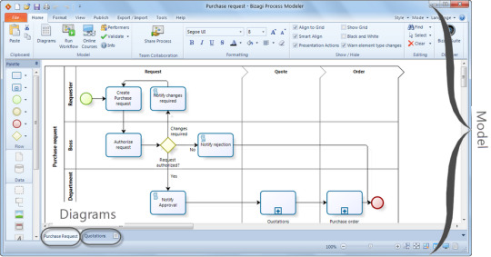
Bizagi Process Modeler For Mac

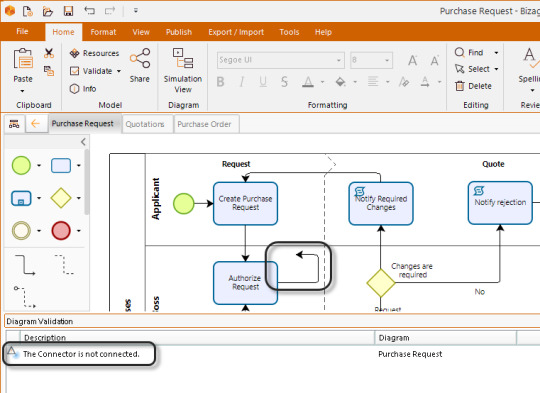
BizAgiProcessModeler 1. Diagram and document your processes with BPMN, in an efficient way and encouraging collaboration in your organization.The first step in the task of improving operational efficiency of an organization is to define its processes.
File Name:BizAgiPMSetup.exe
Author:BizAgi Ltd
License:Freeware (Free)
File Size:38.37 Mb
Runs on:WinXP, Win2003, Win2000, Win Vista
An enhancement of the successful Consideo Modeler. It’s the first easy to use tool to run scenarios (System Dynamics) on constraints (ToC) and the critical chain of processes and projects. Connect to MS-Project, Excel or SQL, create management. ...
File Name:CONSIDEOModeler_Mac.zip
Author:Consideo GmbH
License:Freeware (Free)
File Size:34.2 Mb
Runs on:Mac OS X 10.4.1 or later
To document the processes in standardized, structuralized and efficient way ' Strong reduction of duration and costs for interview, document and validate the processes ' Functionalities that become possible to draw the process during the interview. ...
File Name:ARPO Business ProcessModeler
Author:Klug Solutions
License:Shareware ($)
File Size:57.57 Mb
Runs on:Windows Vista, XP, 2000, 98, Me
Business Process Visual ARCHITECT, a full-featured business processmodeler seriously supporting latest OMG's Business Process Modeling Notation (BPMN). BP-VA provides the most easy-to-use diagramming environment for you to model your business proces. ...
File Name:Business_Process_Visual_ARCHITECT_Windows.exe
Author:Visual ParadigmInternational Ltd.
License:Commercial ($99.00)
File Size:75.47 Mb
Runs on:Cross Platform
AgilPro 1.5.0 offers users with an effective yet beneficial tool which is designed as an Eclipse based business process modeling suite providing a Business ProcessModeler [LiMo - Light Modeler]. It is a desktop application to preview and run. ...
File Name:AgilProSimulator-Installer-mac-ppc_1.5.0.jar
Author:AgilPro Team
License:GPL ($)
File Size:33.6 Mb
Runs on:Mac OS X
Sketchpad is a tool for drawing and editing BPMN (Business Process Modeling Notation) diagrams. Sketchpad process models are serialized and stored as XPDL 2.1 files. Sketchpad was originally developed by Global 360 as ProcessModeler Analyst Edition.
File Name:Sketchpad BPMN
Author:Andy Adler, Robert Shapiro
License:Freeware (Free)
File Size:
Runs on:Windows
The BPMN 2.0 Modeler for Visio is a standalone Visio extension to draw and model business processes. It is a comprehensive user friendly package. The BPMN 2.0 Modeler for Visio supports the complete proposed set of BPMN 2.0 elements (flow objects,. ...
File Name:BPMN 2.0 Modeler for Visio
Author:Trisotech Inc.
License:Freeware (Free)
File Size:17.2 Mb
Runs on:WinXP, Windows Vista, Windows 7, Windows 7 x64
Do you feel your business process has become too complex and unmanageable? Do you find it difficult to visualize your business activities for sharing and discussing with your colleagues? Are you thinking there must be a better tool to design,. ...
File Name:Business_Process_Visual_ARCHITECT_Windows.exe
Author:Visual ParadigmInternational Ltd.
License:Shareware ($99.00)
File Size:97.7 Mb
Runs on:Windows All, Unix, Linux, Mac OS X
The fastest way to capture and share your business process knowledge.Whether providing the transparency demanded by your customers, complying with industry standards and government regulations, or working to improve your existing operational effectiveness, the foundation for all of these initiatives is to have a clear understanding of how your business operates.The Synthis Process Modeler is a flowchart-based documentation tool that makes it .
File Name:SynthisProcessModeler-R4.zip
Author:Synthis Corporation.
License:Shareware ($)
File Size:47.41 Mb
Runs on:WinXP, Win2000, Win Vista
PMN Solution Visualization .NET/VC++ Source Code Kit-- Build Advanced Diagrams and Dashboards for Business Process Management (BPM) in minutes Business Process Modeling (BPM) is typically performed by business analysts who are seeking to improve. ...
File Name:BPMNCheck.zip
Author:ucancode software
License:Freeware (Free)
File Size:492 Kb
Runs on:Win95, Win98, WinME, WinNT 4.x, Windows2000, WinXP, Windows2003, Windows Vista
SDE for IBM WebSphere is a full-featured UML CASE tool seamlessly integrated with IBM WebSphere. SDE supports full software development life-cycle - analysis, design, implementation, testing and deployment. SDE supports the latest UML notation,. ...
File Name:sdeceec.jar
Author:Visual Paradigm
License:Freeware (Free)
File Size:82 Mb
Runs on:Win95, Win98, WinME, WinNT 3.x, WinNT 4.x, WinXP, Windows2000, Windows2003, Unix, Linux
SDE for IBM WebSphere is a full-featured UML CASE tool seamlessly integrated with IBM WebSphere. SDE supports full software development life-cycle - analysis, design, implementation, testing and deployment. SDE supports reverse engineering (Java code. ...
File Name:sdeceec.exe
Author:Visual Paradigm
License:Freeware (Free)
File Size:82 Mb
Runs on:Win95, Win98, WinME, WinNT 3.x, WinNT 4.x, WinXP, Windows2000, Windows2003
A reusable Sub-process is called a Call Activity in BPMN. The element has a thick border. Event Sub-process. A Sub-process is defined as an Event Sub-process when it is triggered by an Event. An Event Sub-Process is not part of the normal flow of its parent Process - there are no incoming or outgoing Sequence Flows. Bizagi helps organizations to modeler transform. Details the original Bizagi pic. Design a business process model using bizagi by Vakras. Take a of series online series your pace own how learn to at automate.
Bizagi Modeler For Mac

Bizagi Modeler is very intuitive, and the visual display of the process maps is fantastic. The initial setup was simple, online resources are very helpful and customer service is excellent. The ability to share the process models has encouraged us to build a larger system.
Bizagi process modeller free download - Bizagi Modeler, Bizagi Studio, Bizagi for Windows 10, and many more programs.
Related:Bizagi Process Modeler - Ca Process Modeler - Process Modeler - Process Modeler Download - Ca Erwin Process Modeler
Bizagi Process Modeler For Mac Windows 10
Pages : 1 | 2 | 3>
1 note
·
View note
Text
Sequence UML Diagram Assignment Homework Help
http://databaseonlineassignmenthelp.com/Sequence-UML-Diagram.php
Sequence UML Diagram Homework Assignment| Sequence UML Diagram Online Support| Course Help with Sequence UML Diagram
DatabaseOnlineAssignmentHelp has helped innumerable student in acquiring the grades which they long for. Our dedicated approach and the student’s faith helped us in becoming one of the best Sequence UML Diagram Assignment help Provider. Students have to mail their assignment at [email protected] or submit it directly on our website www.DatabaseOnlineAssignmentHelp.com we will respond with the perfect solution on time. Our help will bring better understanding and knowledge of Sequence UML Diagram Applications.
#Sequence UML Diagram Assignment Homework Help#Sequence UML Diagram Assignment Help#Sequence UML Diagram Homework Help#Sequence UML Diagram Online Help#Sequence UML Diagram Project Help#Sequence UML Diagram Assignment Homework Help Experts
0 notes
Text
Omnigraffle windows diagram software

#Omnigraffle windows diagram software for mac
#Omnigraffle windows diagram software software
#Omnigraffle windows diagram software professional
#Omnigraffle windows diagram software windows
It allows you to create a simple sentence with the help of diagramming tools. 1aiway Sentence Diagrammerġaiway Sentence Diagrammer is another distinctive tool for Sentence diagramming and is available to use online and has an application for its users. The interactive tool helps to create grammatically correct sentences with ease and convenience. You can create customized sentences using this efficient Sentence diagramming app playing with your own words and sentences. It helps you to automatically analyze as well as diagram the sentences.
#Omnigraffle windows diagram software windows
Sentence Diagrammer for windows is an extension of Sentence Diagrammer specially designed for Windows users. It also allows you to try a random quote, save/open your favorite sentences as images, text, and app files, copy diagrams to clipboard, diagram from Internet Explorer. It also allows you to change the style of your blackboard, chalk, and diagrams. It helps to create a sentence by comparing up to 3 sentences side by side, which helps you create a better version of your sentence. Sentence Diagrammer App allows you with its unique feature of Reed-Kellogg diagrams with which you can be creative with your sentence structure. It is compatible with iPad and other Apple devices and is widely used in academic work by students.
#Omnigraffle windows diagram software for mac
Logos is a free sentence diagramming tool, particularly for Mac users, enabling them to easily create diagrams and flowcharts. It keeps students engaged while providing in-depth knowledge of work. It is widely used by teachers to improve the efficiency of their students’ work in projects and research papers. It helps students from all backgrounds to improve their literacy and grammar rules.
#Omnigraffle windows diagram software software
Sentence Analytics is a beginner’s software for students to handle complex sentence structure effectively. This tool helps align a sentence, phrase, or clause in a more precise and structured form. It was initially created by the University of Central Florida and can be used for non-commercial, educational, and research purposes. SenDraw is a complete package for your sentence composition as it contains features for well-organized sentence structure without error. Also, it can be used for Business Processes and Mind Maps to create a flowchart, BPMN, organization charts, process flow, mind maps, feature lists, decision trees, and visual notes. It is helpful for Software UML and Network Designs and helps in case diagrams, sequence diagrams, class diagrams, state diagrams, ER diagrams, data flow diagrams, network diagrams, and ArchiMate. It is of comprising importance not only for students but also for individuals working in finance, business, law firms, or any software house. It is as easy as you draw using your pen and paper. It helps you to draw flowcharts and diagrams intuitively. DrawExpress for AndroidĭrawExpress is a distinctive tool for Sentence Diagramming and can recognize gestures much more quickly. OmniGraffle, like other diagramming tools, also provides additional tools, style brush, rubber stamp, browse action tool, magnet, hand, floating tool palette, and a lot more to optimize the objects in a document. It contains tools like drag and drop, selection, shape, line, text, pen, and point editor tool used to alter the text according to the suitable structure. It can be used for Documents & Organization in a way that you can access recent documents and the entire collection of stencils and templates by Resource Browser or Document Picker.
#Omnigraffle windows diagram software professional
OmniGraffle is an extensive and professional tool used for Sentence Diagramming. However, the following are some of the tools with salient features for your better understanding. There are numerous Sentence Diagram Generators with their unique features. Following are some sentence diagramming examples. Diagramming a sentence can be fun and helpful at the same time. It implies straight and diagonal lines in an arrangement to write a perfect sentence. Sentence Diagramming is a visual representation of structuring a sentence to get a more precise outcome. The syntax is arrangements of words to create a well-structured sentence, phrase, or clause, and you can create a proper syntax with the help of diagramming tools. You might have learned this technique in your school but let’s take a revision over it. The Sentence Diagramming technique will allow you to construct a better and more well-structured sentence. A sentence consists of different parts of speech arranged in a structured way. It sometimes gets tricky to construct a merely simple sentence. Your phrase can be constructed with better sentence structure with the help of Diagramming tools.
0 notes
Text
Diagrams

UML 2 use case diagrams overview the usage requirements for a system. They are useful for presentations to management and/or project stakeholders, but for actual development you will find that use cases provide significantly more value because they describe 'the meat' of the actual requirements. Figure 1 provides an example of a UML 2 use case diagram.
Use case diagrams depict:
If you are looking for ready-to-go charts and diagrams, you have come to the right place. Take your pick in our wide collection of free charts and diagrams for PowerPoint and Google Slides! More than 700 options are waiting for you! Since there is a chart for every objective and a diagram for every occasion, we have assembled a varied and extensive selection of editable and easy-to-customize. Diagrams.net (formerly draw.io) is free online diagram software. You can use it as a flowchart maker, network diagram software, to create UML online, as an ER diagram tool, to design database schema, to build BPMN online, as a circuit diagram maker, and more. Draw.io can import.vsdx, Gliffy™ and Lucidchart™ files. Page could not be loaded. We would like to show you a description here but the site won’t allow us.
Use cases. A use case describes a sequence of actions that provide something of measurable value to an actor and is drawn as a horizontal ellipse.
Actors. An actor is a person, organization, or external system that plays a role in one or more interactions with your system. Actors are drawn as stick figures.
Associations. Associations between actors and use cases are indicated in use case diagrams by solid lines. An association exists whenever an actor is involved with an interaction described by a use case. Associations are modeled as lines connecting use cases and actors to one another, with an optional arrowhead on one end of the line. The arrowhead is often used to indicating the direction of the initial invocation of the relationship or to indicate the primary actor within the use case. The arrowheads are typically confused with data flow and as a result I avoid their use.
System boundary boxes (optional). You can draw a rectangle around the use cases, called the system boundary box, to indicates the scope of your system. Anything within the box represents functionality that is in scope and anything outside the box is not. System boundary boxes are rarely used, although on occasion I have used them to identify which use cases will be delivered in each major release of a system. Figure 2 shows how this could be done.
Packages (optional). Packages are UML constructs that enable you to organize model elements (such as use cases) into groups. Packages are depicted as file folders and can be used on any of the UML diagrams, including both use case diagrams and class diagrams. I use packages only when my diagrams become unwieldy, which generally implies they cannot be printed on a single page, to organize a large diagram into smaller ones. Figure 3 depicts how Figure 1 could be reorganized with packages.
In the example depicted in Figure 1 students are enrolling in courses with the potential help of registrars. Professors input the marks students earn on assignments and registrars authorize the distribution of transcripts (report cards) to students. Note how for some use cases there is more than one actor involved. Moreover, note how some associations have arrowheads - any given use case association will have a zero or one arrowhead. The association between Student and Enroll in Seminar (in the version shown in Figure 4) indicates this use case is initially invoked by a student and not by a registrar (the Registrar actor is also involved with this use case). Understanding that associations don't represent flows of information is important; they merely indicate an actor is somehow involved with a use case. Information is flowing back and forth between the actor and the use case, for example, students would need to indicate which seminars they want to enroll in and the system would need to indicate to the students whether they have been enrolled. However, use case diagrams don't model this sort of information. Information flow can be modeled using UML activity diagrams. The line between the Enroll in Seminar use case and the Registrar actor has no arrowhead, indicating it is not clear how the interaction between the system and registrars start. Perhaps a registrar may notice a student needs help and offers assistance, whereas other times, the student may request help from the registrar, important information that would be documented in the description of the use case. Actors are always involved with at least one use case and are always drawn on the outside edges of a use case diagram.
Figure 2. Using System boundary boxes to indicate releases.
Figure 3. Applying packages to simplify use case diagrams.
Creating Use Case Diagrams
I like to start by identifying as many actors as possible. You should ask how the actors interact with the system to identify an initial set of use cases. Then, on the diagram, you connect the actors with the use cases with which they are involved. If an actor supplies information, initiates the use case, or receives any information as a result of the use case, then there should be an association between them. I generally don't include arrowheads on the association lines because my experience is that people confuse them for indications of information flow, not initial invocation. As I begin to notice similarities between use cases, or between actors, I start modeling the appropriate relationships between them (see the Reuse Opportunities section).
The preceding paragraph describes my general use case modeling style, an 'actors first' approach. Others like to start by identifying one actor and the use cases that they're involved with first and then evolve the model from there. Both approaches work. The important point is that different people take different approaches so you need to be flexible when you're following AM's practice of Model With Others.
Reuse Opportunities
Figure 4 shows the three types of relationships between use cases -- extends, includes, and inheritance -- as well as inheritance between actors. I like to think of extend relationships as the equivalent of a 'hardware interrupt' because you don't know when or if the extending use case will be invoked (perhaps a better way to look at this is extending use cases are conditional). Include relationships as the equivalent of a procedure call. Inheritance is applied in the same way as you would on UML class diagrams -- to model specialization of use cases or actors in this case. The essay Reuse in Use Case Models describes these relationships in greater detail.
Remaining Agile
So how can you keep use case modeling agile? First, focus on keeping it as simple as possible. Use simple, flexible tools to model with. I'll typically create use case diagrams on a whiteboard, as you see in Figure 5 which is an example of an initial diagram that I would draw with my project stakeholders. AM tells us that Content is More Important Than Representation so it isn't a big issue that the diagram is hand drawn, it's just barely good enough and that's all that we need. It's also perfectly okay that the diagram isn't complete, there's clearly more to a university than what is depicted, because we can always modify the diagram as we need to.
In parallel to creating the sketch I would also write a very brief description of each use case, often on a whiteboard as well. The goal is to record just enough information about the use case so that we understand what it is all about. If we need more details we can always add them later either as an essential/business use case or a system use case. https://extraload977.tumblr.com/post/657340998419169280/space-falcon-reloaded.
Source
This artifact description is excerpted from Chapter 5 of The Object Primer 3rd Edition: Agile Model Driven Development with UML 2.
Hdr Express LLC is a Texas Domestic Limited-Liability Company (Llc) filed On June 23, 2020. The company's filing status is listed as In Existence and its File Number is. The Registered Agent on file for this company is Alain Sivilla Perez and is located. Welcome to HR Xpress! HR Xpress provides you with tools & information to manage your RR Donnelley work life. Hdr express 3 download. HDR Express is a Shareware software in the category Miscellaneous developed by Less Stress Instructional Services. The latest version of HDR Express is 3.1.1.12800, released on. It was initially added to our database on. HDR Express runs on the following operating systems: Windows. The download file has a size of 11.1MB. 4K 4k cinematography 4K video 32 float adobe Apple bracketing canon cinema5D cinematography digital cinema digital photography DJI drone fstoppers.com fujifilm gear hdr hdr discounts hdr expose HDR expose 2 hdr express hdr software high dynamic range iphone mirrorless camera new nik nikon panasonic petapixel photo gear photogear photography.
Translations
Diagrams Definition
Disclaimer
The notation used in these diagrams, particularly the hand drawn ones, may not conform perfectly to the current version of the UML for one or more of reasons:
Diagrams Of Dna Nucleotides And Bases
The notation may have evolved from when I originally developed the diagrams. The UML evolves over time, and I may not have kept the diagrams up to date.
I may have gotten it wrong in the first place. Although these diagrams were thoroughly reviewed for the book, and have been reviewed by thousands of people online since then, an error may have gotten past of us. We're only human.
I may have chosen to apply the notation in 'non-standard' ways. An agile modeler is more interested in created models which communicate effectively than in conforming to notation rules set by a committee.
Diagrams Examples
If you're really concerned about the nuances of 'official' UML notation then read the current version of the UML specification.
0 notes
Text
Sequence Diagram Of University Management System

Data Flow Diagram For University Management System Draw A Sequence Diagram For Online University Admission System Process Flowchart Area Charts Dfd Diagram For A College. This video will show you how to draw a UML sequence diagram in 5 steps.We will walk through an example of withdrawing money from an ATM.The sequence diagram.
Sequence Diagram Of University Management System Example
System Sequence Diagram Maker
UML Tutorial
UML 2.0 Overview
UML Useful Resources
Utilities
Selected Reading
How to create use case diagram 1. List main system functions (use cases) in a column: –think of business events demanding system’s response –users’ goals/needs to be accomplished via the system –Create, Read, Update, Delete (CRUD) data tasks –Naming use cases – user’s needs usually can be translated in data tasks 2.
Feb 11, 2016 - UML Diagrams College-School-Course administration. Programs and Notes for MCA. Masters in Computer Applications. Simple Programs.
Object diagrams are derived from class diagrams so object diagrams are dependent upon class diagrams. Dreamsky wall clock.
Object diagrams represent an instance of a class diagram. The basic concepts are similar for class diagrams and object diagrams. Object diagrams also represent the static view of a system but this static view is a snapshot of the system at a particular moment.
Object diagrams are used to render a set of objects and their relationships as an instance.
Purpose of Object Diagrams
The purpose of a diagram should be understood clearly to implement it practically. The purposes of object diagrams are similar to class diagrams.
The difference is that a class diagram represents an abstract model consisting of classes and their relationships. However, an object diagram represents an instance at a particular moment, which is concrete in nature.
It means the object diagram is closer to the actual system behavior. The purpose is to capture the static view of a system at a particular moment.
The purpose of the object diagram can be summarized as −
Forward and reverse engineering.
Object relationships of a system
Static view of an interaction.
Sytrus is a reliable hybrid audio synthesizer, available in two versions, as a standalone application and a plugin for FL Studio.Its goal is to help music aficionados generate interesting sounds. Sytrus. Sytrus is a powerful and versatile synthesizer featuring six customizable oscillators (operators). It can perform FM (Frequency Modulation), RM (Ring Modulation/Amplitude Modulation), Subtractive and Additive synthesis. It includes 3 filter modules, an effects module with chorus, three delay lines and unique, per-voice programmable.
Understand object behaviour and their relationship from practical perspective
How to Draw an Object Diagram?
We have already discussed that an object diagram is an instance of a class diagram. It implies that an object diagram consists of instances of things used in a class diagram.
So both diagrams are made of same basic elements but in different form. In class diagram elements are in abstract form to represent the blue print and in object diagram the elements are in concrete form to represent the real world object.
To capture a particular system, numbers of class diagrams are limited. However, if we consider object diagrams then we can have unlimited number of instances, which are unique in nature. Large digital calendar. Only those instances are considered, which have an impact on thesystem.
From the above discussion, it is clear that a single object diagram cannot capture all thenecessary instances or rather cannot specify all the objects of a system. Hence, the solution is −

First, analyze the system and decide which instances have important data and association.
Second, consider only those instances, which will cover the functionality.
Third, make some optimization as the number of instances are unlimited.
Before drawing an object diagram, the following things should be remembered and understood clearly −
Object diagrams consist of objects.
The link in object diagram is used to connect objects.
Objects and links are the two elements used to construct an object diagram.
After this, the following things are to be decided before starting the construction of the diagram −
The object diagram should have a meaningful name to indicate its purpose.
The most important elements are to be identified. Skillshare florist.
The association among objects should be clarified.
Values of different elements need to be captured to include in the object diagram.
Add proper notes at points where more clarity is required.
The following diagram is an example of an object diagram. It represents the Order management system which we have discussed in the chapter Class Diagram. The following diagram is an instance of the system at a particular time of purchase. It has the followingobjects.
Customer
Ryobi cs30. Order
SpecialOrder
NormalOrder
Now the customer object (C) is associated with three order objects (O1, O2, and O3). These order objects are associated with special order and normal order objects (S1, S2, and N1). The customer has the following three orders with different numbers (12, 32 and 40) for the particular time considered.
The customer can increase the number of orders in future and in that scenario the object diagram will reflect that. If order, special order, and normal order objects are observed then you will find that they have some values.
For orders, the values are 12, 32, and 40 which implies that the objects have these values for a particular moment (here the particular time when the purchase is made is considered as the moment) when the instance is captured
The same is true for special order and normal order objects which have number of orders as 20, 30, and 60. If a different time of purchase is considered, then these values will change accordingly.
The following object diagram has been drawn considering all the points mentioned above
Where to Use Object Diagrams?
Object diagrams can be imagined as the snapshot of a running system at a particular moment. Let us consider an example of a running train
Now, if you take a snap of the running train then you will find a static picture of it having the following −
A particular state which is running.
A particular number of passengers. which will change if the snap is taken in a different time
Here, we can imagine the snap of the running train is an object having the above values. And this is true for any real-life simple or complex system.
In a nutshell, it can be said that object diagrams are used for −
Making the prototype of a system.
Reverse engineering.
Modeling complex data structures.
Understanding the system from practical perspective.
Creating UML diagrams for course management system helps teachers to manage course, material distribution and assignments better and communicate with students conveniently.
Course management system is a software system designed for teachers, instructors and students that simplifies the tasks of managing course content, course administration and interaction to help them organize and facilitate instruction. It only only work as a tool for distance education but also supplements to face-to-face classroom learning. Both teachers and learners can monitor the system.
A UML use case diagram is a graphic depiction of the interactions among the elements of a system. It also uses actors and use cases to model the functionality of a system.
Usages of UML Use Case Diagram
UML use case diagram is one of UML diagrams which can model dynamic view of a system. And its specific purpose is to gather requirements and actors of system. It is mainly used in analyzing systems requirements and high level design, modeling the context of a system, reverse and forward engineering.
5 Steps to Create UML Diagrams for Course Management System

Run Edraw, navigate to Software and double click UML Model Diagram to open a blank drawing page.
Drag relevant UML symbols from left libraries and drop on the drawing page.
Double click the symbols to add information and finish typing by click any blank area on the page.
Drag proper connector from left libraries to connect symbols.
Click Save on File tab to save the diagram as the default format .eddx. Or choose Save as on File tab to save as other formats. You can also choose to save in local files or save in your Cloud. Hit Export & Send under File to export the uml diagram as images, ppt , web documents and so on.
Here is the finished uml diagram for course management system.
EdrawMax: a swiss knife for all your diagramming need
Effortlessly create over 280 types of diagrams.
Provide various templates & symbols to match your needs.
Drag and drop interface and easy to use.
Customize every detail by using smart and dynamic toolkits.
Compatible with a variety of file formats, such as MS Office, Visio, PDF, etc.
Feel free to export, print, and share your diagrams.
Software to Create UML Diagrams for Course Management Systems
Sequence Diagram Of University Management System Example
Following handy features of Edraw UML Diagram creator which almost makes everything ready enables it to be one of the most popular UML Diagram Software.
A large amount of standard UML symbols are offered for users to drag and drop. No drawing skills required.
Numerous UML templates are provided for users to download free and customize contents to meet their different demands.
Inserting data by adding hyperlinks, note, and attachments is supported to make UML diagrams interesting and more resourceful.
More UML Diagrams Types
Following are more examples of UML use case diagram.
System Sequence Diagram Maker
UML Diagrams for Traffic Control System
Related Articles
0 notes
Video
youtube

buy research paper
About me
Buy Research Paper For An A Grade .Guaranteed!
Buy Research Paper For An A Grade .Guaranteed! Both tables are used to calculate a “whole necessities desk,” which exhibits how much whole output immediately and not directly is required primarily based on interindustry relationships per final demand dollar. Then, the entire requirements table is reworked to an employment necessities desk utilizing employment–output ratios that mirror labor productivity. The diagram summarizes the input–output system. On July 31, DHS announced a ultimate rule on the USCIS charge schedule. Investment-associated employment primarily accounted for the whole thing of job declines for the entire economy in 2008. Government-associated spending and employment at the federal stage increased, whereas state and local government-associated spending and employment remained virtually flat. Export-associated spending and employment elevated barely (see figures 7–9). The rule adjusts charges that we charge for sure immigration and naturalization benefit requests to help get well the full operating costs of our providers. Along with social isolation, the clouding of work-family boundaries is a significant challenge for distant staff. Teleworkers working from a house workplace lack the physical and psychological separation between these two domains that exists in a standard office setting, says Golden. On the one hand, household and social obligations can simply bleed over into work hours. But extra often, studies show, teleworkers’ professional obligations tend to increase past the traditional workday, interrupting household time and preventing teleworkers from ever really disconnecting. In 2011 overall employment increased by 1.6 million jobs or 1.3 percent, properly under the job growth following other recessions and slower than PCE-associated gains. Federal authorities–related employment began to decline from its 2010 peak, whereas export-associated employment reached 2007 ranges. By the last quarter of 2008, because the recession deepened, consumers reduce spending by over $200 billion from the previous year to only beneath $9.1 trillion, with decrease purchases of goods, especially vehicles. Employment supported by shopper spending decreased barely as shopper-supported jobs fell by 7,600 . Nearly all PCE-associated employment declines had been confined to goods-producing industries . Federal enterprises are typically intermediate companies, just like the National Flood Insurance Program. In 2012 PCE-associated employment lastly recovered recessionary losses . Because the time series of employment regarding consumption only extends back to 1993, the restoration from the newest recession can solely be in contrast with the 2001 recession. In the 2001 recession, PCE-related employment took 3 years to recuperate to 2001 highs, and total employment took 4 years to recuperate. In the most recent recession, PCE-associated employment recovered in 5 years, whereas complete employment required 7. On the other hand, the share of PCE-related jobs in the retail business hovered round 16.5 percent. In 2011 and 2012, as employment began to recuperate in different sectors, the share of PCE-related jobs in the health care and social assistance sector held regular. With growing older child boomers, nonetheless, upward employment pressure will likely continue for this trade . Table 5 also exhibits the detailed industries with the largest and most speedy features in client-associated employment through the latest recession. Industries that gained essentially the most jobs related to consumer spending had been sometimes within the well being care or education sectors. Faculty, employees, and students have online access to over forty% of UML’s print collections through HathiTrust's Emergency Temporary Access Service. On-premises HPC workloads are available in a variety of sizes and variations. Cloud has been brief on security and performance. HPC IaaS lets you ship excessive-value infrastructure and application providers for even the most demanding HPC necessities. Tables 1 and 4 break out domestic PCE and shopper-related employment by major sector—which are reviewed in more depth within the next section—and determine 6 illustrates quarterly PCE from 2007 by way of 2012. Though most attention in this article is given to 2007–2012 and projections via 2022, long-time period developments for consumption and employment use a time sequence courting again to 1993. Historical BLS publications are relied upon to determine approximate ranges for the interval from 1977 to 1993. Health care and education jobs have been also among the quickest rising for each shopper-associated employment and complete employment. The 10 industries with the most speedy declines in PCE-associated jobs have been all manufacturing industries. Six of the industries with probably the most rapid PCE-associated job declines had been additionally among the prime 10 industries with the most fast declines within the general economic system. The remaining four industries with probably the most fast job declines for the general financial system had been all investment-related within the construction industry. (Note that a number of the industries that shed jobs most quickly when client demand lessened had a low base of consumer-related employment to start with). BLS utilizes enter–output “use” and “make” tables to determine interindustry manufacturing relationships. The “use” table shows what commodities every business makes use of for production , and the “make” desk shows what commodities every trade finally creates .
0 notes
Text
UML Diagram Assignment Help
UML or Unified Modeling Language software is a standardized modeling language in the field of engineering. It is a general-purpose modeling language rich in diagrams and graphic notation, which is used to create visual models of object-oriented software-intensive systems. It is used in the entire software development lifecycle and various implementation technologies. Every single UML diagram helps to create a better software solution individually. Due to this importance of UML in software engineering, universities around the world offer major courses in UML and UML assignments are given to students. Students often find themselves in difficulty when creating UML diagrams due to the plethora of concepts involved. It's also taking a lot of time and as a result, most students start looking for online UML assignment help or UML diagram online support service to complete their UML homework for fear of failing their UML assignment.
We curate our UML assignment homework with complete dedication, diligence and always write in your best unified modeling language assignments that are reflected through your points.
Unified modeling language is a theme in software engineering that is entirely technology based. This can be difficult for students who are from non-technical backgrounds and may face a lot of problems writing their UML assignments. Our integrated modeling language assignment help clarify your concepts and will let you understand the topic in a well defined way.
We ensure that you get maximum benefits at affordable prices so that you choose us again and again and give your reference to other students as well. We help keep every UML diagram online and always write in certain ways so that it reaches the professional level.
What's best for writing your UML assignment?
We have a team of trusted, dedicated and expert UML professionals who have been assigned to UML/UML. UML diagrams are the best in writing all kinds. We are aware of all the skills and expertise needed to create a complete UML diagram. Our experts give your UML assignment their best when writing and taking into account the details of each minute of your UML diagram so that the assignment is completed without any errors. Before the assignment deadline is made sure you get a+ score in your UML assignment.
We also provide faster UML assignment support service to students who have their own UML assignment/assignment support service. There is a paucity of time in presenting UML diagrams i.e. we also work on the basis of ASAP (as soon as possible). We want to help not only complete your UML diagram prematurely and build your excellent reputation in front of your professors and friends, but we also want you to know and understand the basics of UML so that you can become an expert in software engineering.
Our experts curated UML assignment homework with complete dedication and relevant content that it matches the level of university guidelines and ensures that the student gets the best score and our UML assignments help them understand certain concepts and use them in their exams.
We ensure that we keep UML diagram assignment assistance and other UML assignments in a simple format and easy language. Our UML Assignment Help service is available for you with 24*7 and a few easy steps at affordable prices.
You just need 2 minutes to submit details about your need for UML assignment help.
After depositing, you just have to wait a few hours. Our quick update service will continue to notify you.
We begin our work by collecting all relevant information used in UML Diagram Online Help and UML Assignment Help.
Our experts write your assignments in writing well and are then sent to proof-readers, publishers, and editors.
After going through several checks we finally upload it to your profile and allow you to download it.
We are also available for revision after submission.
Pocket-friendly UML diagram assignment helps at affordable prices
Knowing about our affordable prices will match your pocket money savings as it can insist on helping you with UML assignments within hours. Yes, you are going through the right information on our web page because we have set you cheap prices to reduce stress from long UML assignments that take days to complete and you don't get good marks.
Our unified modeling language assignment is assisted for students who want to score better in UML assignments from their batch mates and score A+ grades every time, so that they get the help of UML assignments from us.
We have set cheap prices according to the ability of students to pay because we know that students pay with money most of the time in their college life because they have to pay a lot more with the help of parents. They feel pressured to work hard and are ultimately impressed in their studies due to prolonged spending on assignments.
Therefore, with the help of our UML assignment homework, you will be able to submit your UML assignments in time with unique plagiarism-free content and the hard work of our experts will be reflected in it.
Various topics that cover our UML Diagram Assignment Help Service
Our UML Assignment Help Specialists are leading in writing on all types of UML topics. However, the list below shows the topics on which we primarily provide the UML Assignment Help Service
UML Case Diagram - This is the relationship between the user and the different usage cases that the user involves. The UML diagram represents the user's interaction with the system that is detailed in UML Assignment Help.
UML Activity Diagram - It focuses on the execution and flow of a system behavior. It also describes the dynamic aspects of the system. UML diagram assignment help will have diagrams with a good explanation.
UML Class Diagram – This UML diagram is a type of static classic structure that describes the structure of a system showing the relationship between the system's classes, methods, characteristics and objects.
UML sequence diagram - This is a sequence represented through a diagram which is the arrangement of the object in a time sequence. They occupy interactions between objects in terms of cooperation.
UML State Chart Diagram - State diagram is a depiction of states of an object that achieves transition between UML and states. The diagram of the state chart is useful for modeling a reactive system.
UML Component Diagram - The diagram in it shows how components are wired together to create software systems or large components. UML Assignment Homework will show diagrams related to many physical and technology related aspects.
UML Collaborative Diagram - Collaborative diagram is used to represent the structural organization of the system and messages sent and received. UML assignments also include differences between different types of UML diagrams.
UML Object Diagram - In an objective diagram, some particular set of objectives and attributes and the link between them is focused. Both diagrams are to visualize the stable structure of a system.
UML ER Diagram - Unit-relationship diagram is a representation of data within the domain and includes relationships between entities as well as them. It is used to sketch the design of the database.
UML Deployment Diagrams - These diagrams are used to describe the hardware components where software components are deployed. This includes nodes and their relationships.
Unique features of our UML Assignment Help Service
We have a team of UML assignment writers who have a lot of academic expertise and experience in creating online UML diagrams. We firmly believe in delivering the best quality service to students at an affordable price. We are best at completing UML assignments in time with great professionalism and accuracy.
We help to complete the UML assignment as per the instructions given. We work in a customized way to your liking. We also take into account the guidelines given by your university.
None of our works have been traced to any plagiarism to date which means that we give authentic solutions and work on every job with sincerity. We write our Unified Modeling Language Assignments with our data that are researched by us and not copied from anywhere.
We have a guaranteed UML Assignment Help online service and we ensure that students get the best grades. We have an excellent team of experts who provide UML diagram assignment support with the latest upgraded data and facts that make the assistance of your UML assignment unique.
We provide 24*7 UML diagram assignment support service. If you face any doubts related to questions related to payment problems or topics, we keep ourselves available to you through calls, online chat service and free SMS.
We have professional background writers, including former teacher, Ph.D. Scholars and experienced professionals in UML assignment help service.
We write your UML assignment homework within hours after we submit to us on our web page with the necessary details.
We keep confidentiality about our work provided to you between author and student if you feel anxious.
We make sure you get the best grades as we do uml assignment help service with the latest software, tools and technology.
We are always open for free revision, when we submit your assignments for free and help you understand if there is a problem.
Our expert team incorporates the latest findings, data, facts and well-researched journals in your UML assignment homework that makes it a quality oriented UML assignment.
The assistance of your modified modeling language assignment by editors and publishers is often met with multiple modifications and proof-readings.
UML Diagram Online Help will give you a clear structure of diagrams, which you will be able to explain to your professors.
Our UML diagram assignment help is cheaper than other assignment help services and we don't compromise with the quality of assignments and give it 100% of our own.
If your UML assignment/assignment is available, you can use the UML assignment. You can also contact our expert authors if there is any doubt or confusion in the UML diagram. Our expert UML writers are always there and feel happy to help and help you.
Our payment, feedback and contact methods are safe and secure.
Still thinking? Just relax by transferring your burden to us to write down your UML assignment and free yourself. You will not only pay to complete your UML assignment, but also help for the best UML assignment online service.
Coupon Code
GAHOFF10
to catch
10% off
Using the top of coupon codes
Now Command
Timely Delivery
When you need them and before the expected time frame we provide quality educational papers.
High priority options
Quick Status Updates
Instant order (starting from 3 hours)
Plagiarism Free
Quality assurance experts ensure that the papers written by our professional authors are 100% unique.
Contains proper referrals and quotes
Each paper is tested with anti-plasma tools
Other Services
Network Assignment Assistance
HRM Assignment Help
Homework Help
Programming Assignment Assistance
0 notes
Text
Best Recommended Tools for Business Analysts
A business analyst is one who deals with the requirements gathering, elicitation, analysis, and modeling on a day-to-day basis. For efficient business analysis, tools help in performing the business analysis tasks more quickly and efficiently because nowadays the organization wants their projects very effectively and efficiently. There are a lot of Business analyst tools in the market, but we suggest the most commonly used tools for you.
It is not possible for a business analyst to learn or use all such tools within the span of his work life, One needs some time for the best training and practice of these tools. Hence, in this blog, we have focused only on the best business analysis tools which are commonly used worldwide.
Before using the tools, a business analyst must know about the business analysis techniques and the knowledge areas to implement these top business analysis tools in the correct way.
Here is a list of some useful business analysis tools along with its important features:
BIZAGI
Existing system to monitor traffic coming from outside nodes or the traffic exchanged between internal PC and servers exchanged can be defeated by the volume and variety of traffic. In nutshell, all existing IDS (information detection system) have a limit to produced alerts per unit time but the way IOT is coming up big, these limits will be insufficient to safeguard the enterprise system. Features
Bizagi Modeler is used for drawing diagrams (case management, business process management, process automation, process modeling, low code app development, and business transformation). It follows the Business Process Model and Notation (BPMN.)
It supports Word, PDF, Wiki, and SharePoint.
It provides an agile automation platform.
Balsamiq
In the Business Analyst field, many projects demand wireframing applications to showcase mockups of a proposed system. Typically a wireframing focuses on
Content
User interaction
Balsamiq is among the top business analysis tools for creating wireframes. The tool uses brainstorming sessions and provides immediate feedback from stakeholders. Balsamiq Mockups helps the business to work smarter and faster. In addition to that, it works as a collaboration tool between clients and the team.
Features
Present mockups using PDF along with embedded links
Provides fast and intuitive user interface
Links allow the user to access prototypes for usability testing and demos
Provides enough users interface controls and icons
Creates reusable component libraries and templates
Allows to build wireframes
Extensive library for ready-to-use controls
StarUML
As a business analyst, your main task is for making a lot of Use cases so StarUML is “the most common tool” in this field. StarUML is an open-source software modeling tool that supports UML (Unified Modeling Language).StarUML has a lot of powerful features which makes it more than a “simple” diagramming tool. You can also export your diagram to Pdf, Png, and JPG. Features
Use Case Diagram
Class Diagram
Sequence Diagram
Collaboration Diagram
Statechart Diagram
Activity Diagram
Component Diagram
Deployment Diagram
Composite Structure Diagram
Edraw
Edraw offers optimal tools to make it super easy to create professional-looking business report diagrams, such as sales reports, market research, and business forms, etc. It lets you create all kinds of business report diagrams and then print them, share them directly with your clients. Edraw is a technical diagramming software. In MCAL “ Master Business Analysis Training program “you will use it to create MindMaps. It can also export to Word, PowerPoint, PDF, and Graphics. Features
A complete, all-in-one diagramming tool
Readily-available templates and examples to get started quickly
Advanced formatting tools
There are a couple of theme options to add color and unique styles to diagrams
You Publish your creation online or print out.
Easy to Export or share your work in multiple formats (pdf, doc, ppt, etc.)
Jira
As a business analyst, Jira is the most common tool used in an Agile environment. It is a business analyst and task management tool. It helps every business analyst to plan, track, and report on work. The basic use of Jira is to track issues, and bugs related to your software and Mobile apps. Features
The task management feature helps to track the tasks and status of the task.
Everyone can see the project’s status without having to set up meetings or emails.
The Project Management feature allows managing corporate website designs or employee training programs.
It allows measuring performance in different ways like a quick overview and predefined report
Trello
Trello is the best collaboration tool for business analysis which helps to collaborate, communicate between teams and share information securely. Along with that, it allows admin to examine the business data ( Detailed information of the project Jira). Jira is most commonly used in an Agile environment. Features
It allows users to stay in sync across all of your devices and secure collaboration with the team.
Allows to add members from Google Apps account
Organize and associate boards with Collections
Deactivate old members without losing any history of their work
Dive into the details by adding attachments, comments, and sharing idea more directly to Trello cards
View team activity across boards
Assign admins to manage privacy settings
Export all team’s data and history with a single click
If you want to become a successful business analyst you have to good hands on these tools. So MCAL made their program “ Master Business Analysis Training program “ in such a way that focused on the IIBA BABOK knowledge areas as well as they give you the best practices on these tools by live examples and case studies.
For more information about the business analyst visit our other blogs :
https://www.mcal.in/blog-iiba-ba-ecba-ccba-cbpa/
https://www.mcal.in/blog/why-any-ba-should-go-for-certification-like-ccba-cbap/
https://www.mcal.in/blog/10-business-analysts-resolutions-for-2016/
https://www.mcal.in/blog/how-to-prepare-for-a-business-analyst-interview/
https://www.mcal.in/blog/is-online-ba-training-suitable-for-me/
https://www.mcal.in/page/blog-best-recommended-tools-for-business-analysts
0 notes
Link
UML Assignment HelpUML refers to Unified Modelling Language. We have extended our services to provide you UML assignment help that explicitly explains all the topics grouped under UML. Our tutors are legitimate to provide UML diagrams to students with clear explanation on each.
UML is a Graphical language that is used for constructing, envisaging and verifying the software system. In simple words, it is a method of picturing a software program using some standard diagrams. Earlier, it was used for object-oriented design, but now the use of UML has been extended in various projects of software Engineering. Also, it is recognized by Object Management Group for demonstrating software development. Our online tutors have explained that use of UML is not restricted for software systems, rather anybody who is keen to cognize a system (software or non-software) can use UML diagram.
Learning Modelling skills are important for every programming students. This article is framed to help students recognize the services of cheapassignmenthelp.co.uk for their UML assignment. Our online assignment help service is meant to teach student UML skills along with some useful tips to build a comprehensible knowledge of this subject. Our UML assignment help intend to provide flexible solutions to students for their UML assignment questions.
Our online tutors are always looking forward to provide you assignment help in UML that encloses all the topics of this field. In order to introduce you our online services, they have outlined some major portions of our UML assignment solutions:
1. You can learn about conceptual model and ask for practical conceptual models for your UML Project from our expertise.
3. UML assignment help provided to you by our online tutors clearly explains the topic of UML building block describing about things, relationships and diagrams.
4. Design, process, implementation and deployment are four main perspective of UML. At cheapassignmenthelp.co.uk, you can get every details on these topics.
5. UML modelling is another important topic covered in our UML assignment service that aim to provide clear explanation on Structural Modelling, Behavioral Modelling and Architectural Modelling.
6. Our online UML assignment writing service also covers all the notation used in UML. You can receive homework help in Nodes, interface, object and all other graphical notations.
Students pursuing programming usually look stressed up due to extensive and complicated course structure. Studying Programming requires apparent and subterranean understanding of the entire course that means understanding along with memorizing. For this students need to go beyond the restricted curriculum of their text-book and put effort by practicing and implementing every system and process. This is the reason, studying UML also demands practice, ideas and memorization.
Choosing our service on UML assignment help avails you to secure some free time to broaden your knowledge and develop a coherent concept in this field. Also from our assignment help service in UML, you will be able to acquire and come across some interesting yet useful information that are hardly covered in your class.
Our online experts have notified that Learning UML diagram is very important to execute the ideas and knowledge in real life systems. This is the reason our assignment help service covers this vast yet an important topic. If you want a UML diagram for the provided project, come to us. We will provide you UML diagram assignment help from our proficient experts. UML diagram can be classified into two main categories namely: Structural diagram and Behavioral diagram. To complete a system, static and dynamic parts are required. In a similar way, structural diagram covers static part of UML diagram whereas Behavioral diagram covers dynamic part of UML diagram. Describing each of the components in these diagram, our tutor tells that both these sections require clear understanding to frame an accurate UML diagram.
UML Structural diagram
Class diagram: It characterizes an object oriented view of structural diagram that is static in nature. Classes, associations, collaboration and interfaces is included under class diagram.
Object diagram: It is practical outlook to shape system. Therefore, it can be used to test the precision of class diagram.
Component diagram: It exemplifies executional outlook of a model. Hence, include classes, interfaces and collaborations.
Deployment diagram: The set of nodes and their relationships constitute deployment diagram.
When you seek UML assignment help from our team, we make sure that your topic is covered by the expert proficient in that area. Our team in Programming have degree holder tutors specialized in varied fields. You can directly interact with them to discuss your UML assignment questions.
UML Behavioral diagram
Use case diagram: It represents functionality of a system describing their relationships along with internal and external controllers.
Sequence diagram: It provide outlook on interaction between structures of messages rolling from one piece to other.
Collaboration diagram: This diagram represent structural organization of any object.
State chart diagram: The episode driven state alteration of a system is represented by state chart diagram.
Activity diagram: This diagram allows to arrest complete flow of a system.
ORDER NOW
0 notes
Text
Sequence UML Diagram Assignment Help
Sequence Diagram models the collaboration of objects based on a time sequence which describes an interaction by focusing on the sequence of messages that are exchanged, along with their corresponding occurrence specifications on the lifelines. Sequence diagrams are the most useful reference diagrams for businesses and other organization. DatabaseOnlineAssignmentHelp.com is well equipped with solutions for every Sequence UML Diagram problems, so whenever students feel like they have stuck up and their assignment is heading towards nowhere to find the solution, we can prove to be a facilitator and rescuer. DatabaseOnlineAssignmentHelp.com has helped innumerable student in acquiring the grades which they long for. Our dedicated approach and the student’s faith helped us in becoming one of the best Sequence UML Diagram Assignment help Provider. Our help will bring better understanding and knowledge of Sequence UML Diagram Applications.
0 notes
Text
1802ICT Assignment – Project Planning, Analysis and Design Report Weight: 55% Rationale: The purpose of this assignment is to demonstrate your ability to apply all the concepts of planning and project management to a practical scenario involving a business information system. You are required to thoroughly analyse and design your proposed information system. Groups: You may work in a team of up to two (2) people. Task: You have been contracted by a company to develop an information system for $50,000. During this assignment, you will undertake a thorough systems analysis and design on the proposed system. The business that you design the information system for is of your own choosing. Preferably develop a system for an area that you are interested in, have had prior experience, or perhaps for a company you work for. You cannot design the system for the same company that another student has chosen, nor can you reproduce a design for an existing well-known company. The information system you chose should be of small to medium size/complexity. You are required to deliver the following specifications before the project can commence: 1. Identify the Problem – Provide a system vision document that outlines the problem description, system capabilities, and the expected business benefits (minimum 300 words). (Insert system vision document here) 2. Quantify Project Approval Factors – Complete the following tasks (minimum 500 words): a. Provide a table with a breakdown of the estimated time for project completion using excel or a similar program. (Insert table and explanation here) b. Provide a table with a summary of the development costs for the project and system using excel or a similar program (use Australian dollars). (Insert table and explanation here) c. Provide a table with a summary of the estimated annual operating costs using excel or a similar program (use Australian dollars). (Insert table and explanation here) d. Undertake a cost/benefit analysis: i. Describe the anticipated benefits from the deployment of the new system (outline tangible and intangible benefits). (Insert answer here) ii. Provide a table with a summary of estimated annual benefits. (Insert table and explanation here) 3. Perform a Risk and Feasibility Analysis – Complete the following tasks (minimum 500 words): a. Determine organisational risks and feasibility. (Insert answer here) b. Evaluate technological risks and feasibility. (Insert answer here) c. Assess resource risks and feasibility. (Insert answer here) d. Identify schedule risks and feasibility. (Insert answer here) 4. Establish the Project Environment – Complete the following tasks (minimum 500 words): a. Provide a table outlining information that will be captured during system development, the tools and software that will be used to develop the system, and outline who can update / view the information. (Insert table and explanation here) b. Describe the work environment. (Insert answer here) c. Describe the processes and procedures that will be used. (Page 276) (Insert answer here) 5. Schedule the Work – Complete the following tasks (minimum 300 words): a. Provide a work breakdown structure (WBS) for one (1) of the subsystems. (Insert WBS here) b. Provide a Gantt chart showing the WBS project activities timeline. You must use Microsoft Project and provide a screen capture. (Insert Gantt chart here) 6. Discover and Understand the Requirements – Define the functional and non-functional requirements for the system using the FURPS+ framework (minimum 300 words). (Insert answer here) 7. Identify the internal, external, operational, and executive stakeholders for the system (minimum 300 words). (Insert answer here) 8. Target a specific group of operational stakeholders and create a questionnaire that will be used to collect information about their system needs. Be sure to use a combination of open and closed-ended questions and identify the stakeholder that your questionnaire is targeting (minimum 300 words). (Insert questionnaire here) 9. Identify all the object classes and provide a complete domain model class diagram for the system. You must use Microsoft Visio. (Insert domain model class diagram here) 10. For each subsystem, identify and provide brief use case descriptions for all use cases. (Insert brief use case descriptions here) 11. For one particular subsystem, identify and provide one (1) fully developed use case description. (Insert use case descriptions here) 12. For the identified use case, provide one (1) use case diagram. You must use Microsoft Visio. (Insert use case diagrams here) 13. For the use case diagram provide a corresponding activity diagram to illustrate all the steps within the use case. You must use Microsoft Visio. (Insert activity diagrams here) 14. For the activity diagram provide a corresponding system sequence diagram (SSD). You must use Microsoft Visio. (Insert SSD here) 15. Design the system components – Provide a high-level architectural diagram and explain the environment within which the system will operate (i.e., stand alone, networked, hosting options, cloud infrastructure, etc.) (minimum 300 words). (Insert high-level architectural diagram and explanation here) 16. Provide story boards illustrating the user interface for at least four (4) screens. Discuss how you have applied best-practice user-interface design concepts (minimum 300 words). (Insert user interface diagrams here) 17. Deploy the solution – Describe the approach for planning and managing implementation, testing, and deployment for the system (minimum 500 words). (Insert answer here) You must use Microsoft Project for the Gantt chart and Microsoft Visio for all UML diagrams produced for this assignment, otherwise your answers will not be marked. All diagrams must be part of a single file. Additional files and attachments will not be marked. All tables, diagrams, and charts must be accompanied by a one paragraph description (minimum 100 words) to help explain your rationale and logic. Note that presentation, spelling, and grammar are extremely important aspects of your design. Be sure to proof read your work prior to submission. Submission Information: 1. Compile all the diagrams and specifications professionally into a single MS Word document. (Do not submit a pdf file.) 2. Use the following format for the Word document’s filename: Last Name_First Name_Student Number.doc (e.g., Smith_John_s2841999.doc) 3. Carefully review the assignment marking criteria. 4. Do not compress your assignment file. 5. Submit your assignment online by going to the “Assignment” section of the course web site.
1802ICT Assignment – Project Planning, Analysis and Design Report Weight: 55% Rationale: The purpose of this assignment is to demonstrate your ability to apply all the concepts of planning and project management to a practical scenario involving a business information system. You are required to thoroughly analyse and design your proposed information system. Groups: You may work in a team of up to two (2) people. Task: You have been contracted by a company to develop an information system for $50,000. During this assignment, you will undertake a thorough systems analysis and design on the proposed system. The business that you design the information system for is of your own choosing. Preferably develop a system for an area that you are interested in, have had prior experience, or perhaps for a company you work for. You cannot design the system for the same company that another student has chosen, nor can you reproduce a design for an existing well-known company. The information system you chose should be of small to medium size/complexity. You are required to deliver the following specifications before the project can commence: 1. Identify the Problem – Provide a system vision document that outlines the problem description, system capabilities, and the expected business benefits (minimum 300 words). (Insert system vision document here) 2. Quantify Project Approval Factors – Complete the following tasks (minimum 500 words): a. Provide a table with a breakdown of the estimated time for project completion using excel or a similar program. (Insert table and explanation here) b. Provide a table with a summary of the development costs for the project and system using excel or a similar program (use Australian dollars). (Insert table and explanation here) c. Provide a table with a summary of the estimated annual operating costs using excel or a similar program (use Australian dollars). (Insert table and explanation here) d. Undertake a cost/benefit analysis: i. Describe the anticipated benefits from the deployment of the new system (outline tangible and intangible benefits). (Insert answer here) ii. Provide a table with a summary of estimated annual benefits. (Insert table and explanation here) 3. Perform a Risk and Feasibility Analysis – Complete the following tasks (minimum 500 words): a. Determine organisational risks and feasibility. (Insert answer here) b. Evaluate technological risks and feasibility. (Insert answer here) c. Assess resource risks and feasibility. (Insert answer here) d. Identify schedule risks and feasibility. (Insert answer here) 4. Establish the Project Environment – Complete the following tasks (minimum 500 words): a. Provide a table outlining information that will be captured during system development, the tools and software that will be used to develop the system, and outline who can update / view the information. (Insert table and explanation here) b. Describe the work environment. (Insert answer here) c. Describe the processes and procedures that will be used. (Page 276) (Insert answer here) 5. Schedule the Work – Complete the following tasks (minimum 300 words): a. Provide a work breakdown structure (WBS) for one (1) of the subsystems. (Insert WBS here) b. Provide a Gantt chart showing the WBS project activities timeline. You must use Microsoft Project and provide a screen capture. (Insert Gantt chart here) 6. Discover and Understand the Requirements – Define the functional and non-functional requirements for the system using the FURPS+ framework (minimum 300 words). (Insert answer here) 7. Identify the internal, external, operational, and executive stakeholders for the system (minimum 300 words). (Insert answer here) 8. Target a specific group of operational stakeholders and create a questionnaire that will be used to collect information about their system needs. Be sure to use a combination of open and closed-ended questions and identify the stakeholder that your questionnaire is targeting (minimum 300 words). (Insert questionnaire here) 9. Identify all the object classes and provide a complete domain model class diagram for the system. You must use Microsoft Visio. (Insert domain model class diagram here) 10. For each subsystem, identify and provide brief use case descriptions for all use cases. (Insert brief use case descriptions here) 11. For one particular subsystem, identify and provide one (1) fully developed use case description. (Insert use case descriptions here) 12. For the identified use case, provide one (1) use case diagram. You must use Microsoft Visio. (Insert use case diagrams here) 13. For the use case diagram provide a corresponding activity diagram to illustrate all the steps within the use case. You must use Microsoft Visio. (Insert activity diagrams here) 14. For the activity diagram provide a corresponding system sequence diagram (SSD). You must use Microsoft Visio. (Insert SSD here) 15. Design the system components – Provide a high-level architectural diagram and explain the environment within which the system will operate (i.e., stand alone, networked, hosting options, cloud infrastructure, etc.) (minimum 300 words). (Insert high-level architectural diagram and explanation here) 16. Provide story boards illustrating the user interface for at least four (4) screens. Discuss how you have applied best-practice user-interface design concepts (minimum 300 words). (Insert user interface diagrams here) 17. Deploy the solution – Describe the approach for planning and managing implementation, testing, and deployment for the system (minimum 500 words). (Insert answer here) You must use Microsoft Project for the Gantt chart and Microsoft Visio for all UML diagrams produced for this assignment, otherwise your answers will not be marked. All diagrams must be part of a single file. Additional files and attachments will not be marked. All tables, diagrams, and charts must be accompanied by a one paragraph description (minimum 100 words) to help explain your rationale and logic. Note that presentation, spelling, and grammar are extremely important aspects of your design. Be sure to proof read your work prior to submission. Submission Information: 1. Compile all the diagrams and specifications professionally into a single MS Word document. (Do not submit a pdf file.) 2. Use the following format for the Word document’s filename: Last Name_First Name_Student Number.doc (e.g., Smith_John_s2841999.doc) 3. Carefully review the assignment marking criteria. 4. Do not compress your assignment file. 5. Submit your assignment online by going to the “Assignment” section of the course web site.
1802ICT Assignment – Project Planning, Analysis and Design Report
Weight: 55%
Rationale:
The purpose of this assignment is to demonstrate your ability to apply all the concepts of planning and project management to a practical scenario involving a business information system. You are required to thoroughly analyse and design your proposed information system.
Groups:
You may work in a team of up…
View On WordPress
0 notes
Photo

FreeBSD Unix Architecture // spinellis.gr/blog/20170510 // Today I put online two diagrams depicting the architecture of the Unix operating system, one for the 1972 First Research Edition and one for FreeBSD, one of its direct descendants. Here are the details on how I created these diagrams. The basis of my study was the evolution of Unix facilities over the past five decades. I catalogued the facilities as they appeared in the manual pages in the form of nine tables, one for each section of the Unix manual. For early editions of Unix I hand-cleaned the printed OCRd manuals, while for later versions I wrote scripts to extract the available manual pages from the source code tree. I obtained the source code trees for successive releases from the Unix history repository, a Git repo hosted on GitHub, which contains the history of Unix from its unnamed 1970 PDP-7 edition until today. The corresponding data and code are available online. Then came the problem of depicting the sophisticated architecture in a diagram. Whenever possible, I try to express complex diagrams in a declarative fashion, as text, and then automatically generate their graphical form. For example, I've devised UMLGraph, which allows the declarative specification and drawing of UML class and sequence diagrams. For this case I didn't know a suitable tool that would allow me to draw nested block diagrams. A query on tex.stackexchange.com didn't turn out any useful results, so I decided to create a new small domain specific language for this purpose. The language allows you to specify nested horizontal and vertically labeled boxes. The existence of this language helped me a lot when I created and perfected the FreeBSD diagram over many iterations, and also when I tore the diagram down to bits in order to create the First Edition one. I'm also sure it will prove beneficial for accepting corrections and contributions. The data and code for drawing the diagrams are also available online. I implemented the language as a Python script that parses an input file using regular expressions. As the language grew more complex I found that associating each box type #unix
0 notes