#Serial terminal program for raspberry pi
Explore tagged Tumblr posts
Visit Tumblr Blog
Explore Tumblr blogs with no restrictions, modern design and the best experience.
Last Seen Tumblr Blogs


Fun Fact
Tumblr is used by 21% of adults online aged 18-29 years.
Text
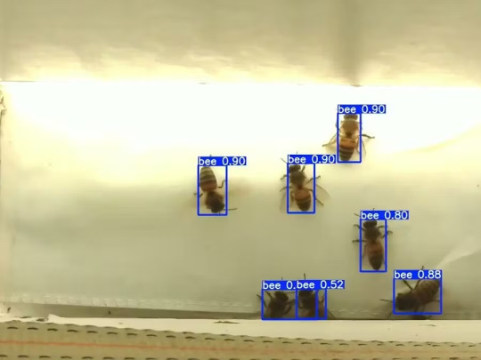
Mixtile Edge 2 Kit– AI based bee detection and tracking
Here I describe usage of Mixtile Edge 2 Kit in agriculture, bee detection, which can be essential for health and survival of bees.
Story
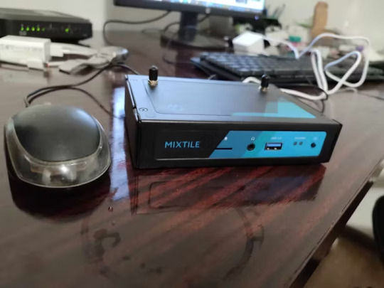
Mixtile is professional IoT hardware solution provider specialized in Linux and Android-based embedded systems.Mixtile Edge 2 Kit is high-performance ARM single board computer. It comes in variants of 2GB of LPDDR4 DRAM and 16GB eMMC Flash storage, or 4GB of LPDDR4 DRAM and 32GB eMMC Flash storage. This single board computer comes with preinstalled Android 11, and it runs Ubuntu Linux operating system in Android container. It comes with large connectivity options (Bluetooth, 4G/5G Cellular, GPS, and Lora, Zigbee and Z-Wave). For those, you will need module, but it comes with default onboard Wi-Fi connectivity, Gigabit Ethernet Port (RJ45) and Serial Port (RS-485). Because it comes with RS-485 port, which is industrial standard, and it comes within a strong metal case, it seems to me that it can be really used in industrial projects. I used official Raspberry Pi 5 power supply in order to power up my Mixtile Edge 2 Kit.So, an idea came to me why not to use it in agriculture, bee detection, which can be essential for health and survival of bees.This project will cover setting up Mixtile Edge 2 Kit, and custom photo dataset form video in order to train custom YOLOv5 bee detection model. YOLOv5 models must be trained on labelled data in order to learn classes of objects in that data.I gathered data from video and trained model on my PC.To train a model, I used python and typed in command line:
python train.py --img 640 --batch 16 --epochs 3 --data coco128.yaml --weights best.pt
My training results are summarized in the following table:
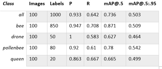
Training results
From this table you can see that images are divided into 4 detection classes:
Bee
Drone
Pollenbee
Queen
Example for each class is summarized in a table below:

Bee classes
1. Getting started
First, I will write about software part of the project, and later on steps of starting the recognition.
1.1 What is YOLOv5?
If you have been in the field of machine learning and deep learning for some time now, there is a high chance that you have already heard about YOLO. YOLO is short for You Only Look Once. It is a family of single-stage deep learning-based object detectors. It was written using Python language, and the framework used is PyTorch.
To ease control, I connected usb mouse to the one of three Mixtile Edge 2 Kit USB3 port. I used Ubuntu Linux for this project. Ubuntu on container is installed in Android system of Mixtile Edge 2 Kit by default. When you boot Mixtile Edge 2 Kit, you get Android OS. Since I wanted to access Edge 2 Kit remotely, and get easier control, I installed droidVNC server from this link:
It is an Android VNC server using Android 5+ APIs. It does not require root access.
I started the VNC server, connected with VNC Viewer and I got the following Android 11 screen:

Android 11
After that, I installed SimpleSSHD from this link:
SimpleSSHD is a SSH server Android app, based on Dropbear.It allows user access (user ssh) or full root access (by setting the login shell to /system/xbin/su) (if root is allowed).
After I installed SSH server, I connected to it via putty SSH terminal. Username and Password are root/root.
Com.hubware.ubuntu is ubuntu on a container and we are connected to it immidiately.
Now we are going to install required software.
First, you will need to upgrade Ubuntu by typing in the command: apt-get upgrade.
Second, I installed python by typing: apt-get install python.
You will also need pip, the package installer for Python.
2. Installing the YOLOv5 Environment
To start off we first clone the YOLOv5 repository and install dependencies. This will set up our programming environment to be ready to running object detection training and inference commands.
Install git: apt-get install git
Clone YOLOv5 repository:
git clone https://github.com/ultralytics/yolov5
Move to YOLOv5 folder:
cd yolov5
Install dependencies:
pip install -r requirements.txt
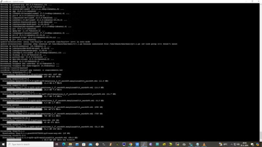
Wait some time to download and install all requirement packages, I waited 25 minutes, because there are a lot of python packages to install besides YOLOv5. YOLOv5 needs numpy package, scipy, OpenCV, etc.
The putty connection and installation process looks like below:
I transferred my model best.pt to the yolov5 installation folder via SCP, with MobaXterm.
You can simply download my model immidiate by typing:
wget https://github.com/sdizdarevic/beedetectionyolov5/raw/main/best.pt
Also, download original video by typing:
wget https://sdizdarevic.typepad.com/cr/bees-orig.mp4
Now, the final step is detection, and we are interested in the “result” content video.
python3 detect.py --weights best.pt --source bees-orig.mp4
The process of detection looks like below:

In the last lines from last picture we can see the detected number of bees at any point in time.
The summarized short steps to follow are below:
git clone https://github.com/ultralytics/yolov5
cd yolov5
pip install -r requirements.txt
wget https://github.com/sdizdarevic/beedetectionyolov5/raw/main/best.pt
wget https://sdizdarevic.typepad.com/cr/bees-orig.mp4
python3 detect.py --weights best.pt --source
Demonstrated videos are on urls with detection finished completely on Mixtile Edge 2 Kit. Output video is in folder runs/detect/exp2.
Original video:
youtube
Result video:
youtube
Last, but not less important: If you want to safely turn off your Mixtile Edge 2 Kit, I recommend you to install Shutdown (no Root) application: https://play.google.com/store/apps/details?id=com.samiadom.Shutdown&hl=en.
3.Conclusion:
After testing I found out that the Mixtile Edge 2 Kit is designed with wide range of applications, from industrial applications, IOT devices, smart home automation, to more than capable AI and edge detection. It is low powered device, with a lot of built-in connectivity options.
I would like to thank amazing Mixtile people for creating this amazing peace of hardware and especially for sending me the Mixtile Edge 2 Kit. Also, Mixtile nurtures the open source values and software, and I believe more people and companies will be involved in making projects with this board.
All in all, I recommend this board for implementing types of projects I described here.
0 notes
Text
Serial terminal program for raspberry pi

#SERIAL TERMINAL PROGRAM FOR RASPBERRY PI HOW TO#
#SERIAL TERMINAL PROGRAM FOR RASPBERRY PI INSTALL#
uarttest06 tlfong01 2019apr08hkt1603 Computer Rpi3B+ Linux hostnamectl raspberrypi Raspbian GNU/Linux 9 (stretch) Linux 4.14.34-v7+ arm Python > sys.version 3.5.3 Test 1 - repeatWriteBytes () - UART port repeatedly send out.
#SERIAL TERMINAL PROGRAM FOR RASPBERRY PI INSTALL#
Then, we'll use Python to install proper libraries to read data from Arduino Uno R3. You may like to compare yours with my working program. We'll start by installing Raspbian Buster Lite in our Raspberry Pi Zero W. Arduino Uno R3 board or compatible board (you can also consider the Elegoo starter kit).micro SD card (at least 16 GB, at least class 10).Raspberry Pi Zero W (including proper power supply or a smartphone micro USB charger with at least a 3A) or newer board.Steps should also work with newer Raspberry Pi boards. What we needįor this project, I'm going to use a Raspberry Pi Zero W and an Arduino Uno R3. Click on the Terminal icon in the top menu bar (or choose Menu > Accessories > Terminal).
#SERIAL TERMINAL PROGRAM FOR RASPBERRY PI HOW TO#
The fastest way to get access to the command line is through the Terminal app. With the second installment on affordable home automation based on Raspberry PI still to come, today I want to show how to access our Raspberry PI terminal through the serial port esto puWith the. For this purpose, we'll use Pyserial and its terminal tool. When you boot a Raspberry Pi, you start by default inside the desktop interface. In this guide, I'll show you how to connect your Raspberry Pi to a serial USB port and read its values with Python from the terminal (without a desktop environment). You can also use Raspberry Pi to dialog with some devices-like Arduino-by using a serial USB port. Raspberry Pi can be used to interface with the real world from its GPIO, for example, by controlling a stepper motor.
0 notes
Text
Teraterm connection refused


When i remove cross over cable, I cannot get response anymore. I also tried updating the driver in the device manager. I tried updating the firmware on the mbed but it hasn't helped. However, the serial option is grayed out. So both ips are the same in first 3 bytes except last byte. Hi, I just downloaded Tera Term to my computer and I am trying to set my 'new connection' to serial for the mbed serial port. But when i use ping for loopback and my window pc ip, i can get reply.
The start of the text selection with the mouse can be delayed by setting. Why my teraterm showed connection refused Omg.
Added the Logging and the Logging menu into the File menu.
Added /OSC52= command line option for change the "Clipboard access from remote" setting.
Added support for xterm ED 3 (clear scroll buffer) control sequence. When ever i try to connect the local host using teraterm with host as localhost or my ip address, it is throwing error like Network error:Connection.
Added support for REP control sequence.
When the opacity values of the Additional settings dialog is input over than 255, the value is automatically changed to 255 over the dialog.
Also, added the BGIgnoreThemeFile entry in the teraterm.ini file.
Eterm look-feel: Added the Mixed ThemeFile to Background configuration.
When transparency is not available, made opacity not changeable.
Added slider for specify the opacity values on the Visual tab of the Additional settings dialog.
The location of resizing tooltip is automatically moved to coordinates after resizing.
When the opacity value of the window is temporarily changed by operating the mouse wheel on the title bar of VT window, the tooltip of the opacity value is shown.
Changed of indication from "Protocol" to "IP version" and from "UNSPEC" to "AUTO" on New connection dialog.
Added SFMT information on version dialog.
I am running out of ideas, any help would be appreciated. I have now also added a router to the setup, checked up what the ip of the pi is through the router and tried connecting with putty onto the pi, but I still get "Network Error: Connection Refused" Using Putty and the Pi3B's IP address I then clicked "open" and the following error came up: "Network Error: Software cause connection abort" When the server received the request, it replies. In Telnet, the client starts the connection request on TCP/23. This connection happened in plain text, including the authentication message.
Telnet allows the client to establish a remote connection to the Telnet server. I unplugged everything from the Pi3, plugged the LAN cable back into my laptop and Pi3 and powered up the Pi3B. Telnet is a basic remote login protocol without all the bell and whistle. Once booted I opened terminal and entered "sudo raspi-config", where I then enabled SSH manually. I then used a Screen and keyboard to boot the Pi 3B. Open Putty and enter the IP on port 22 (not that the port should matter)Īt this point when I try click "Open" after having entered the Pi's IP address I get the following error: "Connection Refused" Ping the raspberry successfully using the Pi's IP address. I have followed the exact same steps I have for my Pi 2B's with exception to the image.ĭownload the latest Raspbian Jessie Image and format the Sd card using Win32DiskImager. There is a client version of SSH (used for remoting into other systems) and a server version (used for accepting incoming connections into the system). I have a new Raspberry Pi 3B and cannot ssh into it at all. The most basic troubleshooting you can do is to first verify that SSH is installed on the system. It emulates different types of computer terminals, from DEC VT100 to DEC VT382. I have two Raspberry Pi 2 B's that I have set up in the past with no issues incl headless setup. Tera Term (rarely TeraTerm) is an open-source, free, software implemented, terminal emulator (communications) program. Heedlessly ssh into a Raspberry Pi 3B on my Win7 platform(s). Thanks for taking the time and helping me out.
1 note
·
View note
Text
Install and use coolterm

INSTALL AND USE COOLTERM INSTALL
INSTALL AND USE COOLTERM SERIAL
Icon=/opt/CoolTermLinux/appicon_128. I have already configure its settings but there are no outputs. It is now possible to change baudrate, byte format. Snaps are discoverable and installable from the Snap Store, an app store with an audience of millions. They update automatically and roll back gracefully. Snaps are applications packaged with all their dependencies to run on all popular Linux distributions from a single build.
INSTALL AND USE COOLTERM INSTALL
The connection options now display port information for the selected port. Enable snaps on Raspberry Pi and install cool-retro-term. NEW FEATURES: New Connection options window with multiple pages. This is a major release which includes many new features and improvements.
INSTALL AND USE COOLTERM SERIAL
Sudo apt install libicu-dev:i386 libcanberra-gtk-module:i386 libgtk-3-dev:i386 libharfbuzz-dev:i386 libpango1.0-dev:i386 sudo gedit /usr/share/applications/sktop Coolterm is the serial port debug tool that I use, its all new for me and I dont know how can I check the outputting log from ESP8266 using it. Im happy to announce the release of CoolTerm 1.4.0. Mv ~/Downloads/CoolTermLinux /opt/ sudo apt update & sudo apt upgrade If you are prompted to enter a password, please type your Mac user's login password and press ENTER. Make sure they are both set to the same baud rate and settings. Then, open two serial terminal windows (yes, you can have multiple terminal windows open at once), each connected to a different device. Its got all the necessary features for communicating with hardware devices and an elegant user. Copy and paste the following command in Terminal app: /bin/bash -c ' (curl -fsSL and press enter/return key. CoolTerm was developed as a useful and user-friendly software and acts as a serial port terminal application.CoolTerm is a tool thats geared towards hobbyists and professionals with a need to exchange data with hardware connected to serial ports such as servo controllers, robotic kits, GPS receivers, microcontrollers etc. Connect the TX line of one to the RX line of the other and vise versa. Download the Free Program CoolTerm, or another USB command line application. Previous Post Next Post Installing Coolterm, the Best Serial Terminal In Linux CoolTerm is a very popular cross-platform serial console application developed by Roger Meier. However, if your use of the Mintaka DUO / DUO+ / STAR data requires a.
0 notes
Text
A Peek at the Pico, Raspberry Pi's Newest Petite Powerhouse
Raspberry Pi Pico
8.80 / 10
Read Reviews
Read More Reviews
Read More Reviews
Read More Reviews
Read More Reviews
Read More Reviews


Shop Now
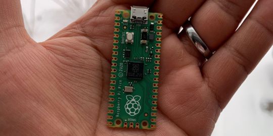
Meet the new Raspberry Pi Pico; a tiny microcontroller filled with big possibilities.
Specifications
Brand: Raspberry Pi
CPU: Dual-core 133Mhz ARM
Memory: 264Kb
Ports: microUSB
Pros
Powerful ARM Processor
Micro-USB Connectivity
Breadboard Mountable
Easy-To-Use Interface
Absolutely Adorable
Inexpensive
Cons
No Wi-Fi or Bluetooth connectivity
No Header Pins
I/O Port Labelling on One Side Only
No USB-C Connectivity
Buy This Product
Raspberry Pi Pico other
Shop
// Bottom var galleryThumbs1 = new Swiper('.gallery-thumbs-1', { spaceBetween: 10, slidesPerView: 10, freeMode: true, watchSlidesVisibility: true, watchSlidesProgress: true, centerInsufficientSlides: true, allowTouchMove: false, preventClicks: false, breakpoints: { 1024: { slidesPerView: 6, } }, }); // Top var galleryTop1 = new Swiper('.gallery-top-1', { spaceBetween: 10, allowTouchMove: false, loop: true, preventClicks: false, breakpoints: { 1024: { allowTouchMove: true, } }, navigation: { nextEl: '.swiper-button-next', prevEl: '.swiper-button-prev', }, thumbs: { swiper: galleryThumbs1 } });
We’ve managed to get our hands on the coveted Raspberry Pi Pico. Today, we’re going to be looking at some of the most important features and putting it toe-to-toe with some of the biggest names in small electronics.
We’ll be showing you what the Pico can do, and we’ll get you started with MicroPython, one of Pico’s supported programming languages. We’ll even offer up some code to try in case you decide to buy a Pico of your own.
What Is a Raspberry Pi Pico?
Raspberry Pi Pico is a new budget microcontroller designed by Raspberry Pi. It’s a tiny computer built around a single chip, with onboard memory, and programmable in/out ports. Historically, microcontrollers are used in a variety of devices from medical implants to power tools. If you have an electronic device sitting in your vicinity, there’s a good chance that there’s a microcontroller inside of it.
Key Features of the Pico

The Pico is built around the RP2040 microcontroller chip, which was designed by Raspberry Pi UK. It’s a Dual-Core ARM processor with a flexible clock that can run up to 133 MHz. The Pico also supports 1.8-5.5 DC input voltage, has a micro-USB input port, and an onboard temperature sensor.
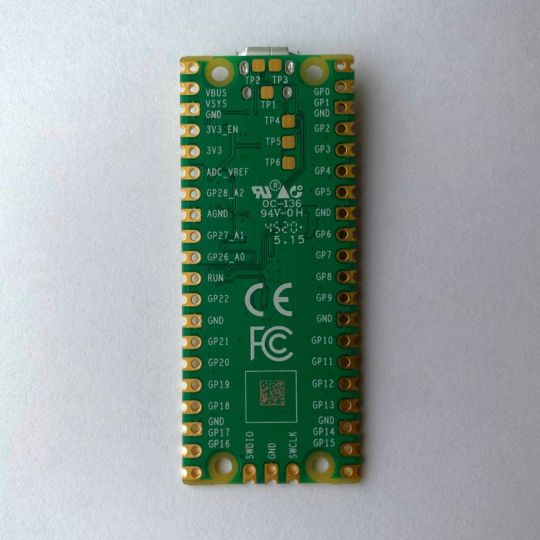
Flanking the chip on all sides are a series of castellations that allow easy soldering to a Veroboard or breadboard. This dual in-line package (DIP) style form factor is stackable, and can also be used in carrier board applications.
Technical Specifications
21 mm x 51 mm
264kb on-chip RAM
2 MB on-board QSPI flash
2 UART
26 GPIO
2 SPI controllers
2 ISC controllers
16 PWM channels
Accelerated integer and floating-point libraries
3-pin ARM Serial Wire Debug (SWD) port
What’s So Special About the Pi Pico?
The Pi Pico is a different kind of microcontroller. It’s Raspberry Pi’s first, and it features ARM technology in its RP2040 silicon chip. Many technology companies are embracing silicon ARM chips, with major manufacturers like Apple leading the charge.
The punchy little Pico packs a staggering 26 multifunction general purpose input/output (GPIO) ports, including 3 that are analog. Alongside these ports are 8 programmable input/output (PIO) ports. Compare this to other microcontrollers like the Arduino Nano, and the Pico packs roughly 18% more GPIO capability.
The most considerable difference between the Pico and its competitors, however, is the $4 price tag. Low cost is the main selling point of this unique offering.
At launch, many online retailers sold out of the device due to the interest and Raspberry Pi’s favorable reputation. By setting the price so low, the Pico opens the door for a new class of high-powered, budget microcontrollers.
There are many potential applications for the new Pico. With its onboard temperature sensor, the device is an obvious choice for IoT projects.
One talented retro gaming enthusiast even used a Pico to build a gaming console with full VGA video support.
youtube
This means that makers who have been curious about Raspberry Pi, or microcontrollers in general, now have the ability to experiment for less than the price of a fancy cup of coffee.
Related: The Raspberry Pi Comes of Age With the Pi 400 Desktop
The Raspberry Pi Pico Processor
The RP2040 ARM chip is an interesting choice for the Pico. At 133MHz, the chip is capable of leaving more expensive boards, like the Arduino Uno, in the dust.
Using ARM processors seems to be an emerging trend in the world of microcontrollers. In addition to Raspberry Pi, both Sparkfun and Adafruit also offer boards with similar ARM technology.
The industry-wide switch was made for a single reason—speed. ARM processors give a considerable boost over standard Atmel chips. In a board this size, using an ARM processor is like dropping a fully kitted Porsche engine into a Volkswagen. On the other hand, many microcontrollers don’t require that much processing speed. Yet.
Ramping up performance means that makers who want to push the limits of the Pico will have an abundance of power to do so.
The I/O Ports
The GPIO ports on the Pi Pico feature several interesting functions for common uses such as operating a screen, running lighting, or incorporating servos/relays. Some functions of the GPIO are available on all ports, and some only work for specific uses. GPIO 25, for example, controls the Pico’s onboard LED, and GPIO 23 controls the onboard SMPS Power Save feature.
The Pico also has both VSYS (1.8V — 5.5V) and VBUS (5V when connected to USB) ports, which are designed to deliver current to the RP2040 and its GPIO. This means that powering the Pico can be done with or without the use of the onboard micro-USB.
A full list of the I/O ports is available on Raspberry Pi’s website in its complete Pico documentation.
Pico vs. Arduino vs. Others
One question on the minds of many makers is whether or not the Raspberry Pi Pico is better than Arduino?
That depends. Pound-for-pound, higher-end Arduino boards like the Portenta H7 make the Pico look like a toy. However, the steep cost for a board of that caliber might be a tough pill for the microcontroller hobbyist to swallow. That's why the smaller price tag on the Pico makes it a win for makers who enjoy low-risk experimentation.
Along with minimal cost, the Raspberry Pi jams an extensive feature set into the Pico, comparable to boards like the Teensy LC, and the ESP32. But neither of these competitors manage to challenge the budget-friendly Pico on price.
That's what makes the Pico such a fantastic value, and a great choice for hobbyists and power users alike.
The Pi Pico: What’s Not To Love?
Unfortunately, to drive the price of the Pico down, Raspberry Pi had to make a few compromises. The most notable of which is the lack of an onboard radio module. Neither Bluetooth nor Wi-Fi is supported without add-ons.
The Wi-Fi limitation can be eliminated by adding a module like the ESP-01. Bluetooth support may prove a bit more challenging. If you need an all-in-one solution for your products, you’re better off skipping the Pico, and spending a little extra for something like the Pi Zero W, or ESP32.
Additionally, many early adopters are complaining about the lack of GPIO labeling on the top of the board. Raspberry Pi provides an extensive amount of documentation on its website to address this, but pointing-and-clicking, or thumbing through paperwork when you have a hot soldering iron in your hands isn’t often desirable.
Lastly, the lack of I/O pin headers is something of an issue for some, as it means less convenience when swapping I/O components. This minor annoyance can be solved via the use of leads, soldering the component wiring directly to the Pico, or using a breadboard.
If you’ve been using microcontrollers or small electronics for any period of time, then an unpopulated board is most likely a non-issue. Of course, you could also add your own pin headers if you plan on regular experimentation with different external components.
The final rub with the Pico is the micro-USB port. With many other microcontrollers like the Portenta H7 moving toward USB-C, Raspberry Pi's micro-USB port seems dated.
Logically however, the decision to use micro-USB makes sense. It was done by Raspberry Pi to keep costs as low as possible, and to keep interface capability almost universal. Everyone we know has at least a few micro-USB cables tucked away somewhere in their homes.
However, with future versions, a USB-C interface would be a nice addition to an already spectacular package.
Related: A Beginners Guide To Breadboarding With Raspberry Pi
Programming the Raspberry Pi Pico
Interfacing with the Pi Pico can be done via C/C++, or via MicroPython in the Read-Eval-Print-Loop or REPL (pronounced “Reh-pul”). The REPL is essentially a command line interface that runs line-by-line code in a loop.
In order to access the REPL, you’ll need to install MicroPython onto the Pico. This process is simple and only involves four steps.
Installing MicroPython
Download MicroPython for Raspberry Pi Pico from the Raspberry Pi Website
Connect the Pico to your computer via micro-USB while holding the BOOTSEL button
Wait for the Pico to appear as an external drive
Copy the MicroPython file to the Pi Pico, and it will automatically reboot
You can access the REPL in a number of ways. We used the screen command in a macOS terminal window to access the serial bus connected to the Pico. To accomplish this with Terminal, you’ll first open a new terminal window, then type ls /dev/tty*
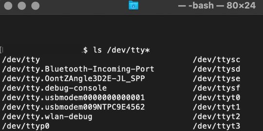
From there, find the port where the Pico is connected. It should be labeled something like /dev/tty.usbmodem0000000000001. Then run the command:
screen /dev/tty.usbmodem0000000000001
Your cursor should change. Hit Return and the cursor will change again to >>>.
In the image below we've included the classic Hello World (Hello, Pico) command-line program in the REPL, along with a few lines of code that will turn the Pico's LED on and off. Feel free to try them yourself.
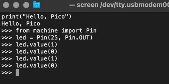
For more information, we recommend you invest in the official starter guide to MicroPython that Raspberry Pi has published on their website.
Download: MicroPython for Raspberry Pi Pico (free)
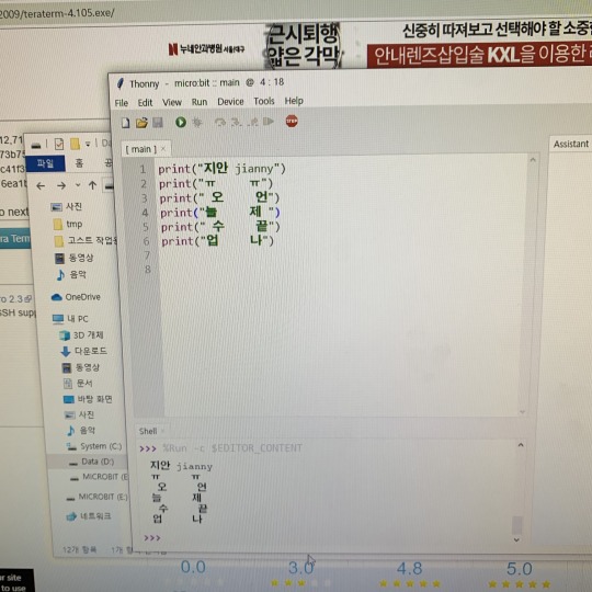
Using the Raspberry Pi Pico With Thonny
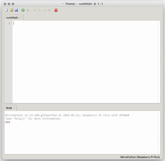
If you’re looking for a more proper coding environment, the Raspberry Pi Pico will also allow access to the REPL with Thonny. To enable this feature, first download and install Thonny. Once installed, connect your Pi Pico. Open Thonny and you'll see information indicating your Pico is connected in the Shell.
At the bottom right of the screen, you should see a version of Python. Click this version and select MicroPython (Raspberry Pi Pico) from the drop-down menu.
Now you can type commands into the Shell, or you can use Thonny’s editor to write or import multiple lines of code.
The abundance of interface possibilities make the Raspberry Pi Pico easy to program. For those who are familiar with MicroPython, this should be nothing new. For beginners, however, Thonny provides a powerful interface and debugger to get started with programming.
Download: Thonny (Free) Windows | Mac
Should I Buy the Raspberry Pi Pico?
The Raspberry Pi Pico is a powerful budget board that is perfect for hobbyists, or makers just starting out with microcontrollers. The documentation, low cost, and wide range of possibilities for the Pico also make it a great choice for seasoned small electronics wizards. If you’re a DIYer who loves to tinker, or you just want to challenge yourself to a weekend project, then you’ll love playing with the Pico.
On the other hand, if you don't have one or more projects in mind that need a microcontroller, then this board is probably not for you. Also, if your project needs Wi-Fi connectivity or Bluetooth, then the Pico won’t scratch that itch. And finally, for users who aren’t comfortable learning MicroPython, or exploring C/C++, the Pico isn't ideal. And remember: this Raspberry Pi is not like the others. It will not run a full Linux operating system.
But, if you dream in Python, or if you love the smell of solder, then you won't regret grabbing this tiny powerhouse. Most of all, if the sight of the sports-car-sleek RP2040 gets your creative gears turning, then we think you’ll really benefit from picking up the Pico.
Serving up Several Sweet Possibilities
While it isn’t perfect, the Raspberry Pi Pico is a strong entry into the world of microcontrollers. The reputation that Raspberry Pi has built for quality electronic components at a relatively low price extends to the Pico.
It’s everything a Raspberry Pi should be: small, sweet, and superb. It’s beautifully designed, and extremely inexpensive. But the best part isn’t the looks or the low cost.
The best part about this small wonder is picking it up, and holding it in your hands. It's feeling the tug of electronic inspiration. It's realizing just how powerful the Pico is, and what it means for microcontrollers going forward.
And truthfully, we think it's amazing that something as small as the Pico can offer so many unique possibilities.
A Peek at the Pico, Raspberry Pi's Newest Petite Powerhouse published first on http://droneseco.tumblr.com/
0 notes
Text
Xamarin.Forms on the Web
TLDR: I implemented a web backend for Xamarin.Forms so that it can run in any browser. It achieves this without javascript recompilation by turning the browser into a dumb terminal fully under the control of the server (through web sockets using a library I call Ooui). This crazy model turns out to have a lot of advantages. Try it here!
A Need
I have been enjoying building small IoT devices lately. I've been building toys, actual household appliances, and other ridiculous things. Most of these devices don't have a screen built into them and I have found that the best UI for them is a self-hosted website. As long as the device can get itself on the network, I can interact with it with any browser.
There's just one problem...
The Web Demands Sacrifice
The web is the best application distribution platform ever made. Anyone with an internet connection can use your app and you are welcome to monetize it however you want. Unfortunately, the price of using this platform is acuquiecense to "web programming". In "web programming", your code and data are split between the client that presents the UI in a browser and the server that stores and executes application data and logic. The server is a dumb data store while the client executes UI logic - only communicating with the server at very strategic points (because synchronization is hard yo). This means that you spend the majority of your time implementing ad-hoc and buggy synchronization systems between the two. This is complex but is only made more complex when the server decides to get in on the UI game by rendering templates - now your UI is split along with your data.
Getting this right certainly is possible but it takes a lot of work. You will write two apps - one server and one client. You will draw diagrams and think about data state flows. You will argue about default API parameters. You will struggle with the DOM and CSS because of their richness in both features and history. You will invent your own security token system and it will be hilarious. The web is great, but it demands sacrifices.
(And, oh yes, the server and client are usually written in different languages - you have that barrier to deal with too. The node.js crew saw all the challenges of writing a web app and decided that the language barrier was an unnecessary complication and removed that. Bravo.)
Something Different
I was getting tired of writing HTML templates, CSS, REST APIs, and all that other "stuff" that goes into writing a web app. I just wanted to write an app - I didn't want to write all this boilerplate.
I decided that what I really wanted was a way to write web apps that was indistinguishable (from the programmer's perspective) from writing native UI apps. If I wanted a button, I would just new it up and add it to other UI elements. If I wanted to handle a click event, I wanted to be able to just subscribe to the event and move on. What I needed was a little magic - something to turn my simple app into the server/client split required by web apps.
That magic is a library I call Ooui. Ooui is a small .NET Standard 2.0 library that contains three interesting pieces of technology:
A shadow DOM that gives a .NET interfaces to the web DOM. It has all the usual suspects <div>, <span>, <input>, etc. along with a styling system that leverages all the power of CSS.
A state-synchronization system. This is where the magic happens. All shadow DOM elements record all the operations that have ever been performed on them. This includes changes to their state (setting their inner text for example) but also methods that have been called (for instance, drawing commands to <canvas>). This state can then be transmitted to the client at any time to fully mirror the server state on the client. With this system, all logic is executed on the server while the client renders the UI. Of course, it also allows for the client to transmit events back to the server so that click events and other DOM events can be handled. This is the part of Ooui that I am the most proud of.
A self-hosting web server (with web sockets) or ASP.NET Core action handlers to make running Ooui very easy. If I want to self-host a button, I simply write:
var button = new Button { Text = "Click Me!" }; button.Clicked += (s, e) => button.Text = "Thanks!"; // Start a web server and serve the interactive button at /button UI.Publish("/button", button);
I can do this from any platform that supports .NET Standard 2. I can run this on a Mac, Linux, Windows, Raspberry PI, etc.
Alternatively, you can host it on an ASP.NET MVC page if you want it up on the internet:
public class HomeController : Controller { public IActionResult Index() { var button = new Button { Text = "Click Me!" }; button.Clicked += (s, e) => button.Text = "Thanks!"; // Return interactive elements using the new ElementResult return new ElementResult(button); } }
Pretty neat huh?
But one more thing...
Xamarin.Forms Support
The DOM is great and all, but what do .NET developers really love when you get right down to it? XAML. This little serialization-format-that-could has become the standard way to build .NET UIs. Whether you're writing a Windows, UWP, or mobile app, you expect there to be XAML support.
So I made XAML work on the web by implementing a new web platform for Xamarin.Forms. Now, any of your Xamarin.Forms apps can run on the web using ASP.NET.
Xamarin.Forms was not at all on my radar when I was building Ooui. Eventually though I realized that it was the perfect basis for a web version of Forms. I thought the idea to be a little silly to be honest - web developers love their CSS and I didn't think there was much point. But one day I heard someone ask for just that feature and I thought "now we're two".
I had never written a backend for Xamarin.Forms but found the process very straightforward and very easy given its open sourceness (e.g. I copied a lot of code from the iOS implementation :-)). There's still a bit of work to be done but Xamarin.Forms and Ooui are getting along like long-lost cousins.
Animations work, pages and layouts work, styling works (as far as I have implemented), and control renders are currently being implemented. Fonts of course are an annoyance and cause a little trouble right now, but it's nothing that can't be fixed.
Once I got Xamarin.Forms working on the web I realized how wrong I was for thinking this to be a silly technology. Writing web apps with the Forms API is a real pleasure that I hope you'll get to experience for yourself.
Now that I am officially releasing Ooui, I want to work on a roadmap. But for now I mostly just want to hear people's opinions. What do you think about all this? What are your concerns? How do you think you could use it? Do you think it's as cool as I do? (Sorry, that last one is a little leading...)
13 notes
·
View notes
Text
What is STONE HMI?- human interface with TOOLBOX sofawsre
An HMI, also known as a human interface, is a display that allows a user to control and monitor his or her machine.A common example of an HMI is an ATM machine, coffee machine, or beauty machine on which the user can interact with the machine using screens and buttons.
Today, through this guide, we will introduce:
Introduction to HMI
HMI and STONE
Why use STONE HMI
STONE HMI display
STONE display starter
HMI project concept
Introduction to HMI - human interface
A human interface is a component of certain devices that allows the user to interact with the machine.
The interface consists of hardware and software that provide information to users by allowing them to input signals that are converted into machines.
Information including temperature, pressure, speed, time, battery and so on!
The interface can also have a variety of forms and sizes, including: 3.5 ', 4.3 ', 5 ', 5.6 ', 5.7 ', 7 ', 8 ', 9.7 ', 10.1 ', 10.4 ', 12.1 ', 15.1 '.
With HMI, you can closely monitor the machine and control and maintain it.This, in turn, can improve efficiency, diagnosis, and monitoring.
One of the biggest benefits of HMI is the user friendliness of the graphical display.You can add colors and images to easily and quickly identify problems.
You can use an HMI almost anywhere you need human intervention with a machine or automated device.For example, you can use them with medical beauty equipment, 3D printers, engineering projects, automobiles, etc.
HMI with STONE
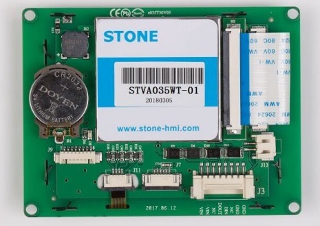
Reference: STONE
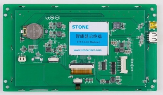
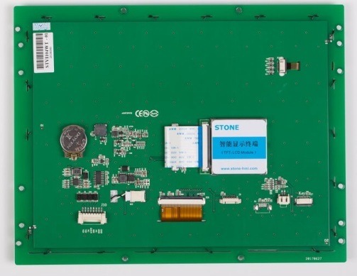
STONE provides intelligent HMI solutions.Any smart TFT LCD module with an MCU (with a cortex-m4 32-bit CPU) can be controlled with simple hexadecimal instructions via the UART port.
The module consists of CPU, TFT drive, flash memory, UART port, power supply and so on.STONE also provides basic controls and powerful design software (STONE TOOL Box).
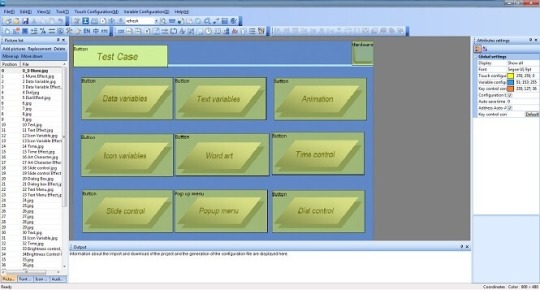
You can use the STONE TOOLBox software to set up various functions on the graphical user interface, such as text, graphics, curves, image switching, keyboard, progress bar, slider, dial, clock and touch buttons, data storage, USB download, video and audio.
Engineers can easily develop the tft-lcd color user interface and touch control features, which can reduce a lot of development time and cost.
STONE is mainly used in the field of industrial electronics.It is the best solution to replace the traditional LCD and LED digital tube.
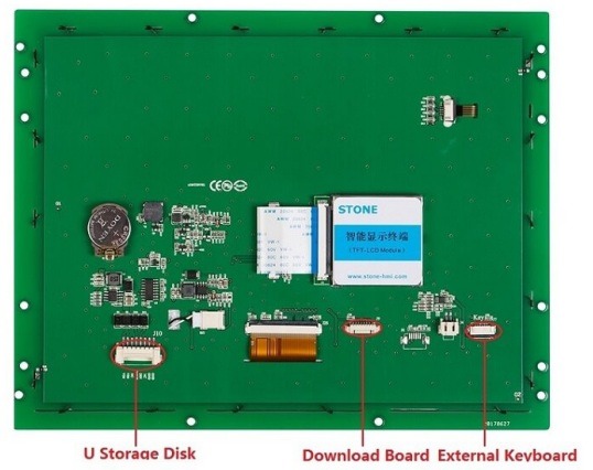
You can easily connect the STONE HMI display via TTL serially through its peripheral MCU to provide event notifications that the peripheral MCU can execute.
With the STONE HMI display TTL serial interface, you can easily connect them to microcontrollers like STM, RAM MCU, Arduino and Raspberry Pi, or any system that can communicate via serial ports.
Why use STONE HMI
Easy to use
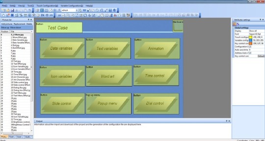
STONE TOOLBox软件
First, STONE is easy to use.With the STONE STONE TOOLBox software, you can easily create intuitive touch user interfaces, even if you're a beginner.
For example, by adding a static image as a background and defining functionality by component, you can easily and quickly create a simple GUI in just a few minutes.
With drag-and-drop components and simple instructions, you don't have to spend a lot of time on HMI project development.
Cost-effective
Engineers can easily develop the tft-lcd color user interface and touch control features, which can reduce a lot of development time and cost
The products are divided into three series, the advanced series for medical beauty, the industrial series for industrial electronics, and the lowest price for civil use.According to their own needs, choose the right type of screen.
Varieties
STONE HMI触摸屏
Various TFT LCD touch screen sizes from 3.5 inches, 4.3 inches, 5 inches, 5.6 inches, 5.7 inches, 7 inches, 8 inches, 10.1 inches, 10.4 inches, 12.1 inches, 15.1 inches, there are many models and options for the same size. With so many HMI displays, you are sure to find the best display for microcontroller projects like STM, RAM, Arduino and Raspberry Pi.。
STONE Support
Need help or technical help with your HMI project?Don't worry, STONE can provide technical support.
Optional UART interface type (RS232/RS485/TTL)
Optional touch control type (resistive/capacitive/non-touch)
STONE HMI Display
Industrial Type
Size Model Brightness Resolution View Area (mm) Voltage(V) Interface 3.5" STVI035WT-01 400 cd/m2 320x240 70.1x53.9 DC6.0-40 RS232/USB 4.3" STVI043WT-01 400 cd/m2 480x272 95x53.9 DC6.0-35 RS232/USB 5" STVI050WT-01 400 cd/m2 480x272 110.9x62.8 DC6.0-35 RS232/USB 5" STVI050WT-03 400 cd/m2 800x480 108x64.8 DC6.0-35 RS232/USB 5.6" STVI056WT-01 300 cd/m2 640x480 112.9x84.7 DC6.0-40 RS232/USB 7" STVI070WT-01 400 cd/m2 800x480 154.1x85.9 DC6.0-35 RS232/USB 7" STVI070WT-03 500 cd/m2 1024x600 154.1x85.9 DC6.0-35 RS232/USB 8" STVI080WT-01 400 cd/m2 800x600 162x121.5 DC6.0-40 RS232/USB 8" STVI080WT-03 400 cd/m2 1024x768 162x121.5 DC6.0-40 RS232/USB 10.1" STVI101WT-01 500 cd/m2 1024x600 222.7x125.3 DC6.0-40 RS232/USB 10.4" STVI104WT-01 350 cd/m2 800x600 211.2x158.4 DC6.0-40 RS232/USB
STONE HMI LCD module specifications:
Cortex m4 CPU; • UART interface (RS232/RS485/TTL) ; • 256-byte register; • 128 kb variable memory; • 128 MB flash memory, expandable to 1 GB; • GUI design software; • The customized command set; • 8-channel curve trend chart memory; • extremely fast variable display response speed; • The single-page supports up to 128 display variables; • Integrated real-time clock RTC, • Touch buzzer sound function; • Support software 90 degrees, 180 degrees, 270-degree screen rotation, adjust the appropriate visual Angle;
STONE TOOL Box (free GUI design software):
-- Free and easy to use STONE TOOL Box software
-- property value components that can be allocated at run time
-- Drag-and-drop components for GUI design and interaction
-- built-in debugger for HMI project emulation
STONE intelligent display module simple instructions:
UseTOOLS 2019 to design a GUI with any .jpg or .bmp image. 2. Use the UART interface (RS232/RS485/TTL) to communicate between the display and your MCU. 3. Use any language to write a simple program for the MCU, let it send the customized hex command sets to read or write the variable value of the display.
STONE LCD sample for developing:
For example: display the time variable "08: 30", and UART send the command: A5 5A 05 82 6F 00 08 30
Description:
A55A: Frame head 05: command byte length, 82 6F 00 08 30 total 5 bytes (excluding frame header) 82: write variable register command 6F 00: Variable address, set in control properties 08 30: data content, BCD code of 08 30
Package Including:
1 * STONE HMI 4.3" TFT 480x272 Resistive Lcd Touch Screen Intelligent Display Module
2 * Transfer board
2 * 8 pin terminal block
2 * 20mm long cable
1 * U disk
1 * USB cable
1 * 5mm short cable
1 * 20mm DB9 cable
STONE authentication and documentation:
- software
- editorial guide
- CE certification
- ROHS certification
- ISO9001 certification
- FC certification
STONE display starter
STONE consists of a hardware section (a series of TFT boards) and a software section (STONETOOL).
The STONE TFT board USES only one serial port for communication, thus avoiding wiring problems for users.
For the software part, STONE is rich in resources.
OSTONE - STONE TOOLBox is Windows software for GUI development.STONE TOOLBox has a number of components, such as buttons, text, progress bars, sliders, dashboards, and more, to enrich the interface design.In addition, drag-and-drop features reduce development effort by 99% by ensuring that users spend less time programming.With the help of this wysiwyg TOOLBox, designing guis becomes easy.
The STONE TOOLBox guide helps you easily set up the STONE TOOLBox.
O can communicate with STM, ARM, Arduino, Raspberry Pi.
The STONE TOOLBox guide helps you set up the STONETOOLBox software.
With these resources, I'm sure you'll have an easy experience on this monitor.
It is also easy to adapt the STONE series HMI to existing project users.You only need to provide one UART.
In addition, if you need any technical support when setting up the STONE display, you can contact STONE technical support.
STONE HMI Display Project idea
Here are some STONE HMI Display project ideas to get you started!
Use the STONE LCD module to create a refrigerator control
Reference: create refrigerator controls
Our fridge is not possible with any of the man-machine interface, but if there is a refrigerator with human-machine interface, let users can through the touch screen operation, control of refrigerator on the lower cooling efficiency, display the current the temperature inside the refrigerator, display the current indoor and outdoor temperature, and some feedback on the usage of refrigerator (days running, filter life, etc.), so, it is very convenient and practical for users.
What do you need?
Temperature sensor
Single chip microcomputer
STVC050WT-01for STM,ARM,Arduino Raspberry Pi general 5.0 inch HMI 480 * 272 touch display
Arduino IDEsoftware
STONE TOOLBoxsoftware
Running state includes:
Operation days
Filter element life
Outdoor temperature
Indoor temperature
To obtain these data, in addition to the first, the other three need the the corresponding sensor to collect these data. Filter element lifetime acquisition sensor and temperature sensor are required respectively. When the single-chip microcomputer collected these data, through the serial port to the designated display control address transmission data, the value of the display control on the corresponding change.
Running days can be implemented in two ways:
Use the RTC of STONE STVC050WT-01 serial port display screento display data directly on the screen
Use the single chip microcomputer's RTC to transfer data to the serial port screen for display
The STONE STVC050WT-01 serial port display comes with the RTC, which can be found in the STONE in development guide.
If you are interested, you can click: create refrigerator controlsSee the full tutorial!
STONE TFT LCD Module acceleration gyroscope sensor
With the STONE HMI display, you can now make an accelerometer gyroscope sensor. The accelerometer gyroscope sensor has the following functions:
Three text boxes display acceleration values
Three text boxes display the gyroscope values
Three text boxes display euler Angle values
A text box displays the current refresh time
Two buttons adjust the refresh time
What Do You Need
STONE advanced STVC070WT-01 universal 7-inch HMI touch screen
STM32F103RCT6 MCU
Mpu-6050 motion processing chip
Photoshop
Watch Dog
MPU-6050 Driver
Are you interested you can click Acceleration Gyroscope Sensor See the full tutorial!
Arduino uno + STONE LCD + Displays data read by MFRC522
reference:Displays data read by MFRC522
Due to my personal interest, I learned about the development of Arduino UNO and STONE LCD module project for two weeks, and found Arduino very simple, convenient and practical.So I wanted to do a simple demonstration with Arduino.I had an MFRC522 module at home, which I used in college, but I used STM32 to communicate with MFRC522, so I had to write my own driver for MFRC522 module, which was very complicated.
What Do You Need
STONE STVC050WT-01 display
Arduino UNO development board
MFRC522 module
Liquid crystal display
The MI card
Are you interested? You can go there https://www.stoneitech.com/news/sharing/how-to-display-data-read-by-mfrc522-through-stone-lcd-with-arduino.html Click to see the full tutorial!
LCD Arduino + STONE HMI +According to the heart rate
reference:instructables.com
Heart rate sensor module MAX30100 can collect users' blood oxygen and heart rate data, easy to use.
I found the MAX30100 library in the Arduino library file.That is, if you use communication between the LCD Arduino and the MAX30100, you can call the Arduino library file directly without having to rewrite the driver file.This is a good thing, so I bought the MAX30100 module.
I decided to use Arduino to verify the MAX30100's heart rate and oxygen collection capabilities.STONE TFT LCD screen for monitoring blood pressure.
What Do You Need
Arduino Mini Pro development board
MAX30100 heart rate and oxygen sensor module
STONE STVI070WT-01LCD serial display module
MAX3232 module
Are you interested you can click instructables.com See the full tutorial!
Conclusion
With STONE Display, you can now easily control and monitor STM, ARM, Arduino or Raspberry Pi machines, applications or device projects!Now, with the STONE STONE TOOLBox software, beginners can also create intuitive touch user interfaces.
What do you think of these STONE HMI displays?Let us know what you think of these STONE displays in the comments section below!
0 notes
Text
Wireless Glove for Hand Gesture Acknowledgment: Sign Language to Discourse Change Framework in Territorial Dialect- Juniper Publishers

Abstract
Generally deaf-dumb people use sign language for communication, but they find it difficult to communicate in a society where most of the people do not understand sign language. Due to which communications between deaf-mute and a normal person have always been a challenging task. The idea proposed in this paper is a digital wireless glove which can convert sign language to text and speech output. The glove is embedded with flex sensors and a 9DOF inertial measurement unit (IMU) to recognize the gesture. A 9-degree of freedom inertial measurement unit (IMU) and flex sensors are used to track the orientation of fingers and motion of hand in three dimensional spaces which senses the gestures of a person in the form of bend of fingers and tilt of the hand fist. This system was tried for its practicality in changing over gesture based communication and gives the continuous discourse yield in local dialect and additionally shows the text on GLCD module. The text show being in English, the voice yield of the glove will be in provincial dialect (here Kannada). So this glove goes about as a communicator which in part encourages them to get their necessities and an interpreter giving greater adaptability in correspondence. In spite of the fact that the glove is planned for gesture based communication to discourse transformation, it is a multipurpose glove and discovers its applications in gaming, mechanical autonomy and therapeutic field.In this paper, we propose an approach to avoid the gap between customer and software robotics development. We define a EUD (End-User Development) environment based on the visual programming environment Scratch, which has already proven in children learning computer science. We explain the interests of the environment and show two examples based on the Lego Mindstorms and on the Robosoft Kompai robot.
Keywords: Sign Language; Flex Sensors; State Estimation Method; 3D Space; Gesture Recognition
Abbrevations: ANN: Artificial Neural Networks; SAD: Sum of Absolute Difference; IMU: Inertial Measurement Unit; ADC: Analog to Digital Converter; HCI: Human Computer Interface
Introduction
About nine thousand million people in the world are deaf and mute. How commonly we come across these people communicating with the normal world? The communication between a deaf and general public is to be a thoughtful issue compared to communication between visually impaired and general public. This creates a very small space for them as communication being a fundamental aspect of our life. The blind people can talk freely by means of normal language whereas the deaf-mute people have their own manual-visual language popularly known as sign language [1]. The development of the most popular devices for hand movement acquisition, glove-based systems started about 30 years ago and continues to engage a growing number of researchers. Sign language is the non-verbal form of intercommunication used by deaf and mute people that uses gestures instead of sound to convey or to express fluidly a speaker’s thoughts. A gesture in a sign language is a particular movement of the hands with a specific shape made out of them [2]. The conventional idea for gesture recognition is to use a camera based system to track the hand gestures. The camera based system is comparatively less user friendly as it would be difficult to carry around.
The main aim of this paper is to discuss the novel concept of glove based system that efficiently translates Sign Language gestures to auditory voice as well as text and also promises to be portable [3]. Several languages are being spoken all around the world and even the sign language varies from region to region, so this system aims to give the voice output in regional languages (here Kannada). For Sign language recognition few attempts have been made in the past to recognize the gestures using camera, Leaf switches and copper plates but there were certain limitations of time and recognition rate which restricted the glove to be portable. Mainly there were two well-known approaches viz. Image processing technique and another is processor and sensor based data glove [4]. These approaches are also known as vision based and sensor based techniques. Our system is also one such sensor based effort to overcome this communication barrier, which senses the hand movement through flex sensors and inertial measurement unit and then transmits the data wirelessly to the raspberry pi which is the main processor, that accepts digital data as input and processes it according to instructions stored in its memory, and outputs the results as text on GLCD display and a voice output.
Background Work
People who are hard of hearing or quiet are isolated in the cutting edge work environment as well as in regular daily existence making them live in their own different networks. For example, there have been enhancements in amplifiers and cochlear inserts for the hard of hearing and counterfeit voice boxes for the quiet with vocal rope harm. Be that as it may, these arrangements don’t come without drawbacks and expenses [5]. Cochlear inserts have even caused a tremendous debate in the hard of hearing network and numerous decline to considerably think about such arrangements. Thusly, we trust society still requires a compelling answer for expel the correspondence obstruction between hard of hearing and quiet people and nonmarking individuals. Our proposed arrangement and objective is to plan a Human Computer Interface (HCI) gadget that can make an interpretation of gesture based communication to content and discourse in provincial dialect, furnishing any hard of hearing and quiet people with the capacity to easily speak with anybody [6]. The thought is to plan a gadget put on a hand with sensors fit for assessing hand signals and after that transmitting the data to a preparing unit which plays out the communication via gestures interpretation. The last item will have the capacity to proficiently perform gesture based communication and give the focused on yield. We want to have the capacity to enhance the personal satisfaction of hard of hearing and quiet people with this gadget.
Comparison of Background Related Work
(Table 1)
Problem Definition
With a population of around 7.6 billion today communication is a strong means for understanding each other. Around nine thousand million individuals are deaf and mute. Individuals with discourse hindrance their vocal articulation are not reasonable, they require a specific skill like static state of the hand orientation to give a sign, more as manual-visual dialect prevalently known as sign language to communicate with general population. They think that it’s hard to impart in a general public where a large portion of the general population don’t comprehend sign language. Hence forth they find a little space to convey and do not have the capacity to impart at a more extensive territory [7].
Literature Survey
The system investigates the utilization of a glove to give communication via gestures interpretation in a way that enhances the techniques for previous plans. Few university research has taken an activity to make prototype devices as a proposed answer for this issue, these devices focus on reading and analyzing hand movement. However, they are lacking in their capacity to join the full scope of movement that gesture based communication requires, including wrist revolution and complex arm developments (Table 2).
Proposed System
(Figure 1)
Block Diagram Explanation
The sensor based system is designed using four 4.5 inch and two 2.2-inch flex sensors which are used to measure the degree to which the fingers are bent. These are sensed in terms of resistance values which is maximum for minimum bend radius. The flex sensor incorporates a potential divider network which is employed to line the output voltage across 2 resistors connected as shown in Figure 2.
The output voltage is determined using the following equation,
Where;
R1 - flex sensor resistance. R2 - Input resistance.
The external resistor and flex forms a potential divider that divides the input voltage by a quantitative relation determined by the variable and attached resistors. For particular gestures the current will change, as a result of the changing resistance of the flex sensor which is accommodated as analog data. One terminal of flex sensor is connected to the 3.3Volts and another terminal to the ground to close the circuit. A 9-Degree of Freedom Ardu Inertial Measurement Unit (IMU) is essential for accelerometer and gyroscope readings which is placed on the top of the hand to determine hand position. The co-related 3D coordinates are collected by the inertial measurement unit as input data [8]. The impedance values from flex sensors and IMU coordinates for individual gesture are recorded to enumerate the database. The database contains values assigned for different finger movements. When the data is fed from both flex sensors and IMU to Arduino nano it will be compute and compare with the predefined dataset to detect the precise gesture and transmitted wirelessly to the central processor i.e. raspberry pi via Bluetooth module. Raspberry Pi 3 is programed to display text output on GLCD. Graphic LCD is interfaced with the Raspberry pi3 using 20-bit universal serial bus in order to avoid bread board connection between processor and the display, and a 10Kohm trim potentiometer is used to control the brightness of display unit. Further to provide an auditory speech, pre-embedded regional language voice is assigned for each conditions as similar to the text database which is mapped with the impedance values. Two speakers are used with single jack of 3.5mm for connection and a USB to power-up the speakers [9]. When text is displayed, the processor will search for the voice signal which will be transmitted through speakers.
Methodology (Figure 3)
a) The gesture is served as an input to the system which is measured by both the sensors particularly from the f lex sensor in terms of impedance and the IMU gives the digital values.
b) These values from the flex sensor are analog in nature and is given to the Arduino nano which uses the analog to digital convertor consolidated in it to convert the resistive values to digital values.
c) IMU utilizes the accelerometer/gyroscope sensors to measure the displacement and position of the hand.
d) These qualities from both the sensors are fed to Arduino nano which contrasts it and the values stored in the predefined database, and further transmits this digital data wirelessly to the main processor by means of Bluetooth.
e) Central processor the raspberry pi3 is coded in python dialect for processing the received digital signals to generate the text output, for example, characters, numbers and pictures. Further, the text output is shown on Graphic-LCD display and next text to speech engine, here particularly espeak converter is utilized to give the soundrelated voice output [10].
Finally, system effectively delivers the output as text and auditory voice in regional dialect.
Prototype Implementation and its Working
In this system, the features are extracted from the hardware sensor inputs and the targets are the words in sign language. To realize the design requirements, several hardware components were considered during prototyping. Much of the hardware was selected due to their ease of use and accuracy. The Ardu 9DOF IMU was selected for convenience as it produces the computation necessary for linear acceleration and gyroscopic measurements. The roll, pitch and yaw measurements were found to be roughly ±2° accuracy which is far beyond sufficient for our sign language requirements. Since the flex sensor required additional analog pins, careful planning allowed us to fit the circuit in an agreeable manner on the hand glove. Space was managed to add in the HC05 Bluetooth module onto the device. All the sensors must be placed in a way as to not make contact with each other causing short circuits which and disruption of measurement readings [11]. Electrical tape was necessary to provide insulation for our sensors. The system recognizes gestures made by the hand movements by wearing the glove on which two sensors are attached, the first sensor is to sense the bending of five fingers, the flex sensor of 2.2 inches for thumb and for the other four fingers of 4.5 inches and the second sensor used is 9-DOF Inertial Measurement Unit to track the motion of hand in the three-dimensional space, which allows us to track its movement in any random direction by using the angular coordinates of IMU (pitch, roll and yaw). Since the output of f lex sensor is resistive in nature the values are converted to voltage using a voltage divider circuit.
The resistance values of 4.5-inch flex sensors range from 7K to 15K and for 2.2-inch flex sensor, it ranges from 20K to 40K, as shorter the radius the more resistor value. Another 2.5K ohm resistor is utilized to build a voltage divider circuit with Vcc supply being 3.3volts taken from Arduino nano processor, the voltage values from the voltage divider circuit being analog in nature are given to the Arduino nano processor which has an inbuilt ADC [12]. Further, the IMU senses the hand movements and gives the digital values in XYZ direction called the roll, yaw, pitch respectively. The values from the IMU and values of the flex sensors are processed in the Arduino nano which is interfaced with HC-05 Bluetooth module embedded on the glove which provides the approximate range of 10 meters. The data processed in nano are sent wirelessly through Bluetooth to the central processor i.e. Raspberry Pi which is coded in python, in a way to convert given values into the text signal by searching in database for that particular gesture. In accordance with the digital value received, the impedance values along with 3 dimensional IMU coordinates for each individual gestures are recorded to enumerate the database. The database contains collective resistance values assigned for different finger movements. When the computed data is received by the processor, it is compared with the measured dataset to detect the precise gestures. If the values matches, then the processor sends the designated SPI commands to display the texts according to gestures onto the GLCD and the espeak provides the text to speech facility giving audible voice output in regional language through the speakers. Further, for any next gestures made, both flex sensor and IMU detects and data is compared with the database already present in the processor and if it matches, displays in text format as well as audible output speech will be given by the speakers [13] (Figure 4).
Results
In this prototype system, the user forms a gesture and holds it approximately for 1 or 1.5 seconds to ensure proper recognition. Each gesture comprises of bending of all fingers in certain angles accordingly. Every bend of the sensor (finger) produces unique ADC value so that when different hand gesture is made, different ADC values are produced. Taking such ADC values for 4 different users, a table of average ADC values for each sensor is maintained where F1, F2, F3, F4 and F5 represents the little finger, the ring finger, the middle finger, the index finger and thumb respectively. Table 3 shows the gestures and corresponding words voiced out. The hand signs taken in the prototype can be easily modified using the concept of ADC count according to the user convenience. At the same time the voice output can be changed easily to gives a flexibility in change of language according to different regions (Figure 5).
Applications
a) Voice interpreter for mute people
b) No touch user interface
c) Gaming industry: Hand gestures play a vital role in the gaming industry, especially in first person shooting games. The player can control the character in the game using his hand and this could give a real life experience of the game. Also, virtual reality is gaining grounds in the gaming industry. Combining virtual reality with the gloves with a haptic feedback can give the gamer a real life gaming experience.
d) Controlling a robotic arm using the gloves: The gloves could be used to control a robotic arm. The applications for this system are wide. With incorporation of haptic feedback, the glove -robotic arm interface could also be used in bomb diffusion.
e) Remote medical surgery: In this the surgeon need not be at the physical location to perform the surgery. He could control a robotic arm remotely to perform the surgery and a haptic feedback could give him the feel of actually performing the surgery. But this would require the gesture recognition to be very precise and the transfer of data from the hand to the robotic arm should be without even a tiny glitch.
Advantages
a) Cost effective light weight and portable
b) Real time translation approximately in no time delay
c) Flexible for ‘N’ users with easy operation
d) Fully automate system for mute communication
Future scope
a) The system can be further developed with Wi-Fi connection and enlarged database supporting special characters or symbols.
b) Microsoft Text To Speech (TTS) engine can be utilized to provide compatibility for multiple international languages.
c) An Android application can be developed for displaying the text and speech output on an Android device.
Conclusion
As we discovered that Deaf-quiet individuals utilize communication via gestures to cooperate with others however numerous don’t comprehend this motion dialect. We have built up a sensor based motion acknowledgment framework to undercover signal into local dialect discourse and content yield. In this framework the hard of hearing quiet individuals wear the gloves to perform hand motion, the transformation of content to discourse in provincial dialect and show has been seen to be predictable and dependable. In this way, the proposed framework with the database of 20 words and 15 sentences has been effectively created which changes over the motions into English words or sentences and shows the yield on GLCD and relating voice yield in provincial dialects using espeak. The proposed framework has insignificant equipment mounted on it which makes it dependable, convenient and savvy and more straightforward to speak with the general public [14]. One more requesting where this framework could be utilized as a part without bounds: Helping hand for individuals with Cerebral Palsy; Cerebral palsy usually appears in early childhood and involves a group of permanent movement disorders. The symptom varies with people and often includes poor coordination, stiff muscles, weak muscles, and tremors. Also, the problems with sensation, vision, and hearing, swallowing and speaking have been identified as other symptoms [15,16]. This problem can be solved to a great extent by providing them with a provision to communicate with just a single finger. The frequently used words by such people can be put across to people with just a small movement in the finger and using our state estimation technique it could predict the letters or words [17].
For More Open Access Journals Please Click on: Juniper Publishers
Fore More Articles Please Visit: Robotics & Automation Engineering Journal
#Juniper Publishers#Open Access Journals#Robotics#Neural Networks#Fuzzy logics#Artifical Intelligence
0 notes
Text
Sending data of Wireless Vibration and Temperature to Google sheets
Introducing NCD’s Long Range IoT Industrial wireless vibration and temperature sensor, boasting up to a 2-mile range the use of a wi-fi mesh networking structure. Incorporating a precision 16-bit vibration and temperature sensor, this device transmits incredibly accurate vibration and temperature records at consumer-described durations.

For the duration of Power-Up, this vibration sensor learns “normal” base-line vibration from the monitored device. This base-line vibration is subtracted from regular sampled vibration readings to improve applicable vibration data. Preferably, the monitored device must be off even as the sensor is mastering. Once the sensor stabilizes and starts sending information, the device/equipment being monitored can be powered on. This business IoT wireless vibration sensor samples 3-axis of vibration data for 100ms after which calculate RMS, maximum, and minimal vibration readings. This sensor combines these records with temperature data in a data packet and transmits the result to modems and gateways in the wi-fi variety. Once the transmission is complete, the vibration sensor is going lower back to sleep, therefore minimizing power consumption.
Powered by using just 2 AA batteries and operational life of 500,000 wireless transmissions, a ten years battery life can be expected relying on environmental conditions and the data transmission interval. Optionally, this sensor may be externally powered, making it a perfect choice for wireless vibration monitoring device for industrial equipment. With an open communication protocol, this sensor transmits hardware-encrypted data that may be included with just about any control system or gateway. Data can be transmitted to a laptop, a raspberry pi, to Losant IoT cloud, microsoft® azure® IoT, and an embedded gadget all at the equal time. Sensor parameters and wireless transmission settings can be modified using labview® tracking software on a computer pc.

Long-Range Wireless Mesh Modem with USB Interface

Setting up Node-Red.
The sensor and Zigmo/Router come pre-programmed and work out of the box. In this section, we will set up a sensor and Zigmo link and start receiving data on our PC.
Resources Required
IoT Long Range Wireless Vibration and Temperature Sensor with power source Battery Or External DC.
Zigmo/Router for PC
Googlesheets
PC/Laptop with an OS installed or Any IoT Embedded Device
Steps to install NODE-RED
Now that you have sensors running, we need a way to do something useful with that data.
First of all, you’ll have to install Node-RED.
Once that’s done, you’ll need to enter your command line, or Power Shell for Windows users, navigate to the directory Node-RED is installed in.
Now type “npm i ncd-red-wireless node-red-dashboard“. This will install the nodes required to receive data from your wireless sensors and you can start Node-RED once this is done.
To start node server write node-red in the command prompt or terminal and press enter.
Setting up the nodes
Assuming at this point you’ve started up Node-RED, you should be able to open a browser and navigate to http://localhost:1880, this will open up the flow builder that is the heart of the Node-RED experience.
Steps to build the flow
At this point you’ll be viewing a large blank flow with a long list of nodes on the left-hand side, this sidebar is called the palette.

Go ahead and drag a Wireless Gateway node over to your flow canvas to get started.

ncd-red-wireless Provides the nodes that manage the serial connection, parse incoming sensor data, filter it by specific parameters, and allow you to configure the wireless sensors.
Finding your wireless sensors
Once you’ve added the node you’ll be able to view the info tab, which contains information about the node’s functionality, this tab is well-populated for most node-red packages and contains valuable information, many times you will not need to view any other documentation outside of the info tab, so keep it in mind while you are building your flows if you have a question about how a node works. The next thing we need to do is configure the node, when you first add it you’ll notice that there is a small triangle on the top right corner next to a blue dot, the triangle indicates that the node needs additional configuration, the blue dot indicates that the node has not yet been deployed as part of the flow.
Double click on the node to open up the configuration options.

Click on the pencil icon next to the Serial Device field to configure your USB router, this will open a second configuration panel that only has a few options.

Click on the magnifying glass next to the Serial Port field and select the port that corresponds with your router, then click the “Add” button on top. The Serial Device field will now be populated based on that selection, and you can click “Done”, you now have direct access to your wireless sensors! To view the data coming in.

Now go back to your palette and type “debug” into the search field at the top, grab one of these nodes and drag it to the right of your Wireless Gateway

Double click on it and change “msg.” to “complete msg object” click done

Now draw a line between the two nodes, and click “Deploy” on the top right of the window...

Working with the data
Now out of your wireless sensors data is gathered and it is output to the “debug” tab, this “debug tab” is placed within the right sidebar subsequent to the information tab. To see the information are available in to hit the reset button. In node-red records is surpassed among nodes in a JSON packet. When the msg object comes into the debug tab you may make bigger it to view the overall list of information that comes with it. This is extraordinarily useful in case you need to quickly see which sensors are checking in. The other issue this node gives is an easy way to interchange your router to the network identity that devices in configuration mode document on, simply hit the button on the left of the node and the tool will switch to the configuration network, hit it once more to return it to listening mode. Once we get the wi-fi tool nodes set up, they may be set to routinely configure a sensor whilst it enters configuration mode, so it’s always available to maintain such gateway nodes present at the flow for speedy configuring a device.

Adding the wireless sensors
We need to separate wireless sensor records domestically in order that we are able to display it, we could use a switch node to split out the messages from the gateway based totally on the mac address with or sensor type, but as I referred to, the wireless nodes truly incorporate extra functionality for configuring the sensors, so we’ll start with them to give you an extra entire image of how those structures can work. In case you haven’t already seen packets coming in from both of your sensors, cross in advance and hit the reset button on the only that hasn’t stated. While a sensor assessment in thru any serial device configuration node, the mac address and kind of sensor is cached in a pool so we are able to quickly find it for the duration of this next step.
Grab a Wireless Node from the palette and drag it onto the flow, double click on it to get it configured.

Select the serial device from the drop-down that you used for the Wireless Gateway, now click the magnifying glass next to “Mac Address” and select one of the available options.


You’ll notice this automatically sets the sensor type for you, you can also give it a name to make it easier to identify. As noted in the info tab, the Serial Device for Config field is optional, and we won’t worry about it right now. The node you have just added effectively works as a filter on incoming sensor data, only passing through data for the mac address, or sensor type if no mac address is present.
Now go back to your palette and type “debug” into the search field at the top, grab one of these nodes and drag it to the right of your Wireless Gateway.

Double click on it and click done.

Adding Function Nodes
The function node is used to run JavaScript code against the msg object. The function node accepts a msg object as input and can return 0 or more message objects as output. This message object must have a payload property (msg.payload) and usually has other properties depending on the proceeding nodes.
Now grab a “function” node from the palette, and place it to the right of the Vib/Temp node.

Double click on the node to edit the function node.
Here you have to write a little javascript code to create a condition.

msg.payload = {}; msg.payload.rms_x = parseFloat(msg.data.sensor_data.rms_x); msg.payload.rms_y = parseFloat(msg.data.sensor_data.rms_y); msg.payload.rms_z = parseFloat(msg.data.sensor_data.rms_z); msg.payload.max_x = parseFloat(msg.data.sensor_data.max_x); msg.payload.max_y = parseFloat(msg.data.sensor_data.max_y); msg.payload.max_z = parseFloat(msg.data.sensor_data.max_z); msg.payload.min_x = parseFloat(msg.data.sensor_data.min_x); msg.payload.min_y = parseFloat(msg.data.sensor_data.min_y); msg.payload.min_z = parseFloat(msg.data.sensor_data.min_z); msg.payload.temperature = parseFloat(msg.data.sensor_data.temperature); return msg;
Now Add “http request” node from the palette.

If you double click on it edit http node, you’ll see a “URL” field, here you have to enter the respective link of the google sheet.
Now create a google sheet to store the values of vibration and temperature.
Steps to create a google sheet.
First, open up your browser and type www.google.com and sign up in google account if you haven’t signed in, then click on the six dots on the left of your picture.

Now click on “Drive” to open the google drive.

Click on New>More>Google Forms>Blank Form.

Here you’ll see an untitled form.

Now edit question as RMS_X and click on the “+” button to add another question for other values of vibration and temperature.

Now click on the Three dots beside your picture as shown in the picture below.

Now click on the “Get pre-filled link”.

Now enter random values to Vibration and Temperature fields and click Get link as shown in the figure.

Now paste that link in notepad.

Edit that link as shown in the picture below.

Now go back to form and click on RESPONSES and then click on the google sheet icon as shown in the picture below.

Create a new spreadsheet.

Here you can visualize the values of vibration and temperature.

Now go back to node-red and double click on http request node to edit it, then copy the URL from the notepad that you have saved and paste it in the URL field as shown in the figure.

You can also attach debug node to check the output the http node.
Now connect all the wires.

Click on Deploy button to get them out on the google sheet.

OUTPUT
Now to go google spreadsheet and you’ll see values are coming.


Node-RED Flow
https://github.com/ncdcommunity/IoT-Long-Range-Wireless-Vibration-and-Temperature-Sensor-to-GoogleSheet-using-Node-RED/blob/master/node_red_flow.json
0 notes
Text
2018-03-26 15 LINUX now
LINUX
Linux Academy Blog
Building a Vessel
New Version of LPI Linux Essentials Course
Linux Academy Weekly Roundup 110
Announcing Python 3 for System Administrators
Linux Academy Weekly Roundup 109
Linux Insider
Neptune 5: A Practically Perfect Plasma-Based Distro
LG Offers Open Source webOS to Spur Development in South Korea
Google Opens Maps APIs and World Becomes Dev Playground
New Raspberry Pi Packs More Power
SpaceChain, Arch Aim to Archive Human Knowledge in Space
Linux Journal
The Linux Journal NSA Weekend Reading List: Tails and Tor
5 Minute FOSS: Spinning a custom Linux distribution
Best Desktop Environment
Vivaldi Browser Teams with DuckDuck Go to Enable Private Search, Memory Leak Discovered in GNOME Shell and More
Best Open Source Content Management System
Linux Magazine
Gnome 3.28 Released
Install Firefox in a Snap on Linux
OpenStack Queens Released
Kali Linux Comes to Windows
Ubuntu to Start Collecting Some Data with Ubuntu 18.04
Linux Today
How To Compress And Decompress Files In Linux
8 Ways to Maintain a Clean, Lean Ubuntu Machine
Hands on Corebird: A GTK+ Twitter Client
Install Java on Centos 7
Why so little love for the patent grant in the MIT License?
Linux.com
Purism Librem 13: A Security-Focused Powerhouse of a Linux Laptop
This Week in Open Source News: New ACRN Project For IoT Arrives, Sony Owes PS3 Owners $65 & More
More Tips for Managing a Fast-Growing Open Source Project
7 Steps to DevOps Hiring Success
The Programming Languages You Should Learn Now
Reddit Linux
What uncommon version of Linux are you running and why is it great?
A new massive cryptomining campaign target Linux servers exploiting old flaw
Drivers for Linux adapters..
Keeping It Simple with NuTyX
Is a possible in Abiword use Serial letters without using java files and administrator permissions?
Riba Linux
How to Install HardenedBSD 11 Stable v1100055 plus Gnome desktop and basic applications
How to install Zorin OS 12.3
Zorin OS 12.3 overview | Your Computer. Better. Easier. Faster.
MX Linux 17.1 overview | simple configuration, high stability, solid performance
How to install Neptune 5.0
Slashdot Linux
Flat-Earther's Steam-Powered Rocket Lofts Him 1,875 Feet Up Into Mojave Desert
Breakthrough Study Reveals How LSD Dissolves a Person's Sense of Self
Ask Slashdot: Can FOSS Help In the Fight Against Climate Change?
Tumblr Takes Down 84 Russia-Linked Accounts
'How I Went Dark In Australia's Surveillance State For 2 Years'
Softpedia
Blender 2.79b
Inkscape 0.92.3
digiKam 5.9.0
Links 2.15
Apache 2.4.33
Tecmint
Tilix – A New GTK 3 Tiling Terminal Emulator for Linux
How to Backup Your Files to Amazon S3 Using CloudBerry Backup on Linux
Suplemon – A Powerful Console Text Editor with Multi Cursor Support
Goto – Quickly Navigate to Aliased Directories with Auto-Completion Support
How to Randomly Display ASCII Art on Linux Terminal
nixCraft
Raspberry PI 3 model B+ Released: Complete specs and pricing
Debian Linux 9.4 released and here is how to upgrade it
400K+ Exim MTA affected by overflow vulnerability on Linux/Unix
Book Review: SSH Mastery – OpenSSH, PuTTY, Tunnels & Keys
How to use Chomper Internet blocker for Linux to increase productivity
0 notes
Text
SpotMicro Controller
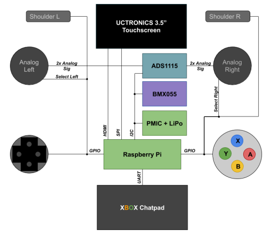
Between Amazon Prime and Netflix and Hulu and HBO Max and this new NBC dedicated channel and Qibi, I thought there was just too much media out there to possibly watch...and then quarantine happened...
My tops for quarantine so far have been
Tales from the Loop
Undone
Bojack Horseman
Infinity Train
to name a few.
But from that first series, Tales from the Loop, come these walky bois:

Fig. 1 Still from Tales from the Loop
I instantly fell in love and it sent me on a trip looking for how the heck to make one of them...I mean, how in the world does a bipedal robot do what it does? From what I read, it’s basically an inverted pendulum problem where the legs are just in charge of catching the center of mass as it swings around. It’s really interesting to boil it down that way, especially when you imagine it can sway side to side.
Instead of jumping straight into the toughest goal (as I usually do and then fail miserably with unfinished projects), I decided to start smallish. So say “Hi” to Spark-E (credit to my wife for the name), my quadruped starting point pal!

Fig. 2 - Pic of my Spark-E (minus the bearings for the joints...was too impatient...)
I just opened up my Ender 3 (vanilla) for the quarantine which gave me a chance to find this project. The frame is 3D printed and takes quite a few days even if you’re going nonstop. I’ve done just the base frame because I have some ideas in mind for how I want to run it and there is a community working on AI around it.
In the meantime, I thought “Hey! I need some kind of a controller. So here is the layout of my dream controller and what I plan to do with it.
At it’s core, the controller will be a battery powered raspberry pi zero w. It will be game controller-ish so you can control the robot like a character.
That means it will have two analog sticks with push-in select buttons on each one. Since Pi’s don’t have ADCs built in, we’ll have to use one on the outside and attach it in. We usually have a choice of SPI or I2C to communicate with these guys, but which one should we use? More on that in a minute.
I want a d-pad for some on-screen menu selection, and some buttons to do neat functions (ugh am i just reinventing an xbox controller?). For that extra controller-like icing on the cake, I’ll stick on some L and R shoulder buttons.
I think it will be really handy to have a screen but I also want text input for the Linux terminal so I’m revisiting the xbox chatpad project from earlier. The chatpad will take up one of my UART lines, and the screen I have (from an earlier project) uses HDMI and is a touchscreen (based on SPI). That means my SPI port is taken up, so our ADC should use I2C.
My ideal controller will also have tilt control which I’ll measure through an IMU. I was already gonna stick one on the SpotMicro so I just bought two.
This is all possible thanks to 40 glorious pins, most of which are usable for signal (the rest are power). Here are how the pins work themselves out for now. If there are changes, I’ll make an updated post:

Fig. 3 - Oof, never again with these trapezoids...Green for serial interfaces, Blue for GPIOs, and Red and Black for power
Everything is 3v3 powered with, of course, similar logic. In my memory, the chatpad was I2C but I was obviously wrong so I’m unfortunately stuck using two valuable pins. :(
So for part selection, here’s what I ended up with:
ADC: 4 single-ended channel ADS1115 IMU: HiLetGo BMX055 9-DOF sensor (I couldn’t discern it from the more expensive Adafruit kind in terms of specs besides that it spits out raw data instead of using an ARM M0 to collect the info into some abstracted numbers) Analog Sticks: DEVMO 5PC sticks XBOX Chatpad (the one I have has the Microsoft branded chip. Get from ebay if you’re cheap! I got mine a long time ago and this is apparently the Amazon listing I followed) Screen: UCTRONICS 3.5″ Touchscreen
I can’t really recommend them or not yet since I haven’t played with them enough yet.
Is it a lot? Yes. Absolutely. Is it even overkill? Are you kidding me? Of course it’s overkill.
On the interfacing side, I really want the controller to be flexible so I’m putting a switch for enabling and disabling bluetooth and wifi. Wifi will let Spark-E join the controller’s network and then we can use some IoT magic to send some commands between them. They’ll be over an encrypted channel but don’t let that throw you for a loop, it’s just the difference between drinking soda through a clear straw vs an opaque one - in the first one, you can see it’s a dark soda and can glean it’s coke, in the second one, you can’t tell, but they’re really similar form factors.
Why Bluetooth? Because I might not just use this with Spark-E. This is gonna be the Big Kahuna of controllers after all! Any new thing I make, I want to use whatever interface makes sense.
Alright, I think I’ve blathered long enough for an intro. Next up are prototyping each of the interfaces. I’m sorry but we’re going to be mixing languages. Sometimes it will be mostly in Python which I’ll throw up on the githubs and then the final program code will be C just because the structure makes sense to me and we can eek out some performance.
Alright! Signing off. More next weekend!
0 notes
Text
A Peek at the Pico, Raspberry Pi's Newest Petite Powerhouse
Raspberry Pi Pico
8.80 / 10
Read Reviews
Read More Reviews
Read More Reviews
Read More Reviews
Read More Reviews
Read More Reviews
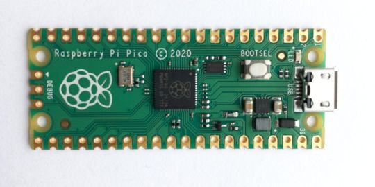

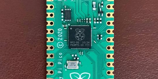
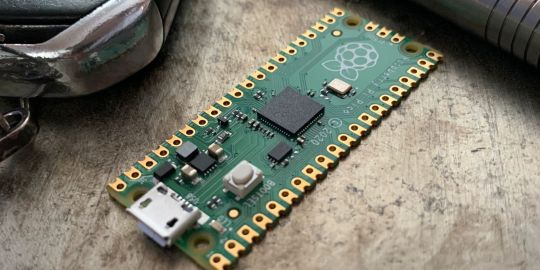
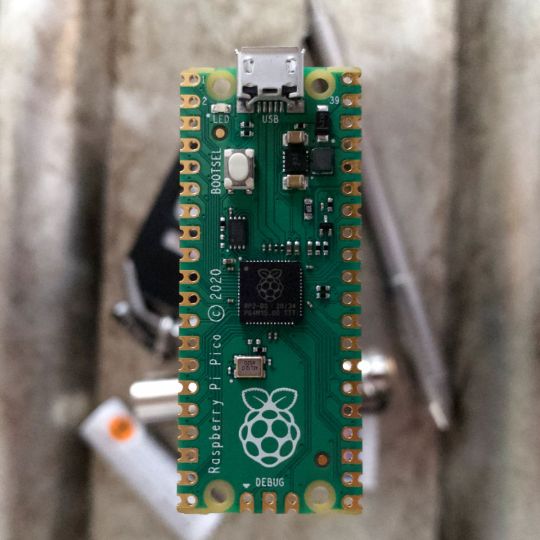
Shop Now
Meet the new Raspberry Pi Pico; a tiny microcontroller filled with big possibilities.
Specifications
Brand: Raspberry Pi
CPU: Dual-core 133Mhz ARM
Memory: 264Kb
Ports: microUSB
Pros
Powerful ARM Processor
Micro-USB Connectivity
Breadboard Mountable
Easy-To-Use Interface
Absolutely Adorable
Inexpensive
Cons
No Wi-Fi or Bluetooth connectivity
No Header Pins
I/O Port Labelling on One Side Only
No USB-C Connectivity
Buy This Product
Raspberry Pi Pico other
Shop
// Bottom var galleryThumbs1 = new Swiper('.gallery-thumbs-1', { spaceBetween: 10, slidesPerView: 10, freeMode: true, watchSlidesVisibility: true, watchSlidesProgress: true, centerInsufficientSlides: true, allowTouchMove: false, preventClicks: false, breakpoints: { 1024: { slidesPerView: 6, } }, }); // Top var galleryTop1 = new Swiper('.gallery-top-1', { spaceBetween: 10, allowTouchMove: false, loop: true, preventClicks: false, breakpoints: { 1024: { allowTouchMove: true, } }, navigation: { nextEl: '.swiper-button-next', prevEl: '.swiper-button-prev', }, thumbs: { swiper: galleryThumbs1 } });
We’ve managed to get our hands on the coveted Raspberry Pi Pico. Today, we’re going to be looking at some of the most important features and putting it toe-to-toe with some of the biggest names in small electronics.
We’ll be showing you what the Pico can do, and we’ll get you started with MicroPython, one of Pico’s supported programming languages. We’ll even offer up some code to try in case you decide to buy a Pico of your own.
What Is a Raspberry Pi Pico?
Raspberry Pi Pico is a new budget microcontroller designed by Raspberry Pi. It’s a tiny computer built around a single chip, with onboard memory, and programmable in/out ports. Historically, microcontrollers are used in a variety of devices from medical implants to power tools. If you have an electronic device sitting in your vicinity, there’s a good chance that there’s a microcontroller inside of it.
Key Features of the Pico
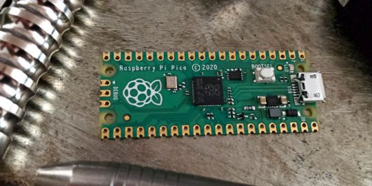
The Pico is built around the RP2040 microcontroller chip, which was designed by Raspberry Pi UK. It’s a Dual-Core ARM processor with a flexible clock that can run up to 133 MHz. The Pico also supports 1.8-5.5 DC input voltage, has a micro-USB input port, and an onboard temperature sensor.
Flanking the chip on all sides are a series of castellations that allow easy soldering to a Veroboard or breadboard. This dual in-line package (DIP) style form factor is stackable, and can also be used in carrier board applications.
Technical Specifications
21 mm x 51 mm
264kb on-chip RAM
2 MB on-board QSPI flash
2 UART
26 GPIO
2 SPI controllers
2 ISC controllers
16 PWM channels
Accelerated integer and floating-point libraries
3-pin ARM Serial Wire Debug (SWD) port
What’s So Special About the Pi Pico?
The Pi Pico is a different kind of microcontroller. It’s Raspberry Pi’s first, and it features ARM technology in its RP2040 silicon chip. Many technology companies are embracing silicon ARM chips, with major manufacturers like Apple leading the charge.
The punchy little Pico packs a staggering 26 multifunction general purpose input/output (GPIO) ports, including 3 that are analog. Alongside these ports are 8 programmable input/output (PIO) ports. Compare this to other microcontrollers like the Arduino Nano, and the Pico packs roughly 18% more GPIO capability.
The most considerable difference between the Pico and its competitors, however, is the $4 price tag. Low cost is the main selling point of this unique offering.
At launch, many online retailers sold out of the device due to the interest and Raspberry Pi’s favorable reputation. By setting the price so low, the Pico opens the door for a new class of high-powered, budget microcontrollers.
There are many potential applications for the new Pico. With its onboard temperature sensor, the device is an obvious choice for IoT projects.
One talented retro gaming enthusiast even used a Pico to build a gaming console with full VGA video support.
youtube
This means that makers who have been curious about Raspberry Pi, or microcontrollers in general, now have the ability to experiment for less than the price of a fancy cup of coffee.
Related: The Raspberry Pi Comes of Age With the Pi 400 Desktop
The Raspberry Pi Pico Processor
The RP2040 ARM chip is an interesting choice for the Pico. At 133MHz, the chip is capable of leaving more expensive boards, like the Arduino Uno, in the dust.
Using ARM processors seems to be an emerging trend in the world of microcontrollers. In addition to Raspberry Pi, both Sparkfun and Adafruit also offer boards with similar ARM technology.
The industry-wide switch was made for a single reason—speed. ARM processors give a considerable boost over standard Atmel chips. In a board this size, using an ARM processor is like dropping a fully kitted Porsche engine into a Volkswagen. On the other hand, many microcontrollers don’t require that much processing speed. Yet.
Ramping up performance means that makers who want to push the limits of the Pico will have an abundance of power to do so.
The I/O Ports
The GPIO ports on the Pi Pico feature several interesting functions for common uses such as operating a screen, running lighting, or incorporating servos/relays. Some functions of the GPIO are available on all ports, and some only work for specific uses. GPIO 25, for example, controls the Pico’s onboard LED, and GPIO 23 controls the onboard SMPS Power Save feature.
The Pico also has both VSYS (1.8V — 5.5V) and VBUS (5V when connected to USB) ports, which are designed to deliver current to the RP2040 and its GPIO. This means that powering the Pico can be done with or without the use of the onboard micro-USB.
A full list of the I/O ports is available on Raspberry Pi’s website in its complete Pico documentation.
Pico vs. Arduino vs. Others

One question on the minds of many makers is whether or not the Raspberry Pi Pico is better than Arduino?
That depends. Pound-for-pound, higher-end Arduino boards like the Portenta H7 make the Pico look like a toy. However, the steep cost for a board of that caliber might be a tough pill for the microcontroller hobbyist to swallow. That's why the smaller price tag on the Pico makes it a win for makers who enjoy low-risk experimentation.
Along with minimal cost, the Raspberry Pi jams an extensive feature set into the Pico, comparable to boards like the Teensy LC, and the ESP32. But neither of these competitors manage to challenge the budget-friendly Pico on price.
That's what makes the Pico such a fantastic value, and a great choice for hobbyists and power users alike.
The Pi Pico: What’s Not To Love?
Unfortunately, to drive the price of the Pico down, Raspberry Pi had to make a few compromises. The most notable of which is the lack of an onboard radio module. Neither Bluetooth nor Wi-Fi is supported without add-ons.
The Wi-Fi limitation can be eliminated by adding a module like the ESP-01. Bluetooth support may prove a bit more challenging. If you need an all-in-one solution for your products, you’re better off skipping the Pico, and spending a little extra for something like the Pi Zero W, or ESP32.
Additionally, many early adopters are complaining about the lack of GPIO labeling on the top of the board. Raspberry Pi provides an extensive amount of documentation on its website to address this, but pointing-and-clicking, or thumbing through paperwork when you have a hot soldering iron in your hands isn’t often desirable.
Lastly, the lack of I/O pin headers is something of an issue for some, as it means less convenience when swapping I/O components. This minor annoyance can be solved via the use of leads, soldering the component wiring directly to the Pico, or using a breadboard.
If you’ve been using microcontrollers or small electronics for any period of time, then an unpopulated board is most likely a non-issue. Of course, you could also add your own pin headers if you plan on regular experimentation with different external components.
The final rub with the Pico is the micro-USB port. With many other microcontrollers like the Portenta H7 moving toward USB-C, Raspberry Pi's micro-USB port seems dated.
Logically however, the decision to use micro-USB makes sense. It was done by Raspberry Pi to keep costs as low as possible, and to keep interface capability almost universal. Everyone we know has at least a few micro-USB cables tucked away somewhere in their homes.
However, with future versions, a USB-C interface would be a nice addition to an already spectacular package.
Related: A Beginners Guide To Breadboarding With Raspberry Pi
Programming the Raspberry Pi Pico
Interfacing with the Pi Pico can be done via C/C++, or via MicroPython in the Read-Eval-Print-Loop or REPL (pronounced “Reh-pul”). The REPL is essentially a command line interface that runs line-by-line code in a loop.
In order to access the REPL, you’ll need to install MicroPython onto the Pico. This process is simple and only involves four steps.
Installing MicroPython
Download MicroPython for Raspberry Pi Pico from the Raspberry Pi Website
Connect the Pico to your computer via micro-USB while holding the BOOTSEL button
Wait for the Pico to appear as an external drive
Copy the MicroPython file to the Pi Pico, and it will automatically reboot
You can access the REPL in a number of ways. We used the screen command in a macOS terminal window to access the serial bus connected to the Pico. To accomplish this with Terminal, you’ll first open a new terminal window, then type ls /dev/tty*

From there, find the port where the Pico is connected. It should be labeled something like /dev/tty.usbmodem0000000000001. Then run the command:
screen /dev/tty.usbmodem0000000000001
Your cursor should change. Hit Return and the cursor will change again to >>>.
In the image below we've included the classic Hello World (Hello, Pico) command-line program in the REPL, along with a few lines of code that will turn the Pico's LED on and off. Feel free to try them yourself.

For more information, we recommend you invest in the official starter guide to MicroPython that Raspberry Pi has published on their website.
Download: MicroPython for Raspberry Pi Pico (free)
Using the Raspberry Pi Pico With Thonny

If you’re looking for a more proper coding environment, the Raspberry Pi Pico will also allow access to the REPL with Thonny. To enable this feature, first download and install Thonny. Once installed, connect your Pi Pico. Open Thonny and you'll see information indicating your Pico is connected in the Shell.
At the bottom right of the screen, you should see a version of Python. Click this version and select MicroPython (Raspberry Pi Pico) from the drop-down menu.
Now you can type commands into the Shell, or you can use Thonny’s editor to write or import multiple lines of code.
The abundance of interface possibilities make the Raspberry Pi Pico easy to program. For those who are familiar with MicroPython, this should be nothing new. For beginners, however, Thonny provides a powerful interface and debugger to get started with programming.
Download: Thonny (Free) Windows | Mac
Should I Buy the Raspberry Pi Pico?
The Raspberry Pi Pico is a powerful budget board that is perfect for hobbyists, or makers just starting out with microcontrollers. The documentation, low cost, and wide range of possibilities for the Pico also make it a great choice for seasoned small electronics wizards. If you’re a DIYer who loves to tinker, or you just want to challenge yourself to a weekend project, then you’ll love playing with the Pico.
On the other hand, if you don't have one or more projects in mind that need a microcontroller, then this board is probably not for you. Also, if your project needs Wi-Fi connectivity or Bluetooth, then the Pico won’t scratch that itch. And finally, for users who aren’t comfortable learning MicroPython, or exploring C/C++, the Pico isn't ideal. And remember: this Raspberry Pi is not like the others. It will not run a full Linux operating system.
But, if you dream in Python, or if you love the smell of solder, then you won't regret grabbing this tiny powerhouse. Most of all, if the sight of the sports-car-sleek RP2040 gets your creative gears turning, then we think you’ll really benefit from picking up the Pico.
Serving up Several Sweet Possibilities
While it isn’t perfect, the Raspberry Pi Pico is a strong entry into the world of microcontrollers. The reputation that Raspberry Pi has built for quality electronic components at a relatively low price extends to the Pico.
It’s everything a Raspberry Pi should be: small, sweet, and superb. It’s beautifully designed, and extremely inexpensive. But the best part isn’t the looks or the low cost.
The best part about this small wonder is picking it up, and holding it in your hands. It's feeling the tug of electronic inspiration. It's realizing just how powerful the Pico is, and what it means for microcontrollers going forward.
And truthfully, we think it's amazing that something as small as the Pico can offer so many unique possibilities.
A Peek at the Pico, Raspberry Pi's Newest Petite Powerhouse published first on http://droneseco.tumblr.com/
0 notes
Text
Why I’m Never Buying an Arduino Again: The Wio Terminal
Our verdict of the SeeedStudio Wio Terminal: Packed full of sensors, buttons, a color LCD screen, and Wi-Fi connectivity, the Wio Terminal from SeeedStudio is fantastic value and well documented. That makes it easy to get on with what's really important: making cool stuff. 910
Electronics programming can be quite frustrating at times. Sourcing components, finding the right libraries to make use of them, figuring out the right parameters to pass in, then hoping there’s some example code to get started with. It all adds up to a massive time suck that detracts from the fun stuff. That’s largely why I’ve fallen out of love with the Arduino ecosystem. SeeedStudio thinks the Wio Terminal might rekindle my relationship with electronics though, and I think they’re right.
The Wio Terminal is an Arduino-compatible development board, crammed full of features and well documented, available for an entirely reasonable $30. Read on to find out why it’s the coolest thing since an Arduino Uno.
Wio Terminal Features and Specifications
The Wio Terminal is built around an ARM Cortex M4F system-on-a-chip, which is a 32-bit ARM processor running at 120Mhz (200Mhz burst). It features 4MB storage, 192k RAM, and there’s a Realtek RTL8720DN wireless chip providing Wi-Fi and Bluetooth connectivity (though the Bluetooth stack wasn’t implemented at the time of writing).
In terms of built-in features, there’s a lot to shout about:
2.4″ color LCD screen
3 pushbuttons
5-way joystick
Buzzer
Micro SD card slot
Light sensor
IR emitter
Accelerometer
Wi-Fi
Bluetooth
USB-C, for client or host mode
Two Grove system connectors
Having an easy-to-use LCD screen is a useful addition to nearly any type of project.
The USB-C connector is how you’ll power the device for now, though a battery kit is expected to be available at a later date. The Wio Terminal can act as both a USB client, to emulate a keyboard, mouse or MIDI device to the host PC; or a host, so it can, for instance, read signals from a wired game controller (though it’s not yet clear how to power it in this mode).
For more complex projects, or those who just prefer Python, the Wio Terminal is able to combine the best of both worlds with ArduPy. You’ll be able to program in Python using the MS Visual Code editor, yet still import your favorite Arduino libraries (or make use of existing ArduPy ones). Personally, I can’t stand Python, but you can learn more about using the Wio Terminal in this way on the SeeedStudio blog.
Getting Started with Wio Terminal
Power on the device with the switch to the left of the screen–and you’ll be immediately greeted by a small Flappy-bird stype retro game (the code for which is available here in case you ever want it back).
You’ll need the Arduino IDE installed to begin programming the Wio Terminal, and to install support for the Wio boards. Enter the URL provided in your preferences, then use the Boards Manager screen and search for Wio.
You’ll find countless code examples for all the various onboard components on the Wio wiki. Many require you to install an additional library into your Arduino Libraries folder, but that’s a simple process (Sketch -> Include Library -> Add Zip).
My first foray involved the sample code for reading accelerometer values and plotting the results on the screen. Very cool, and it really shows off the device’s capability for data logging projects. You’ll also find code for writing values to an SD card.
From there, it was trivial to modify that to read values from the included light sensor instead.
Another ten minutes later, I’d combined the joystick code sample with the LCD fonts demo, to make a simple joystick test program with visual output.
At that point, I wanted to connect another sensor from my bits box, and it was then that I realized there’s a small trade-off to be made in such a polished device. Compared to the barebones board and pin access of the Arduino Uno, it’s a little more difficult to get to the pins on the Wio Terminal. The pinouts for the 40-pin connector can be found in the online documentation, but they aren’t labeled on the device itself and there’s always a risk of plugging in the wrong things.
Which brings us neatly on to the topic of: what options are there for adding components and sensors?
Grove Connectors
On the front of the device are two Grove connectors. Grove is a mature hardware ecosystem that covers every kind of sensor you could possibly want, and more besides.
This is by far the easiest way to add something to the Wio Terminal, and of course, all the Grove components are also well documented with libraries provided. For beginners, it’s a fantastic place to expand from. There’s a small premium on sensors and components within the Grove system, but not a huge amount–and the time you’ll save not having to mess around means it’s absolutely worth it.
For pro users, you can still make use of existing components either through direct pin access on the underside or through the use of Grove system breakout cables. You won’t have as many digital or analog pins as an Arduino, simply because many of them are already in use by on-board components.
Realistically though, how many times have you needed all those IO pins?
Connectivity Options
The model we were sent for review is an engineering prototype, so getting Wi-Fi to work requires a firmware upgrade. It’s a fiddly process and only needs to be done once, but I expect later models to have this ready to go out of the box.
Unfortunately, the Bluetooth hardware is not yet functional. It’s all there on the board, but the libraries needed to use it are not developed yet. Again, this is an early prototype, so I expect a couple of things to unpolished. The Wio Terminal is the latest in a long line of Wio branded devices, and SeeedStudio is an established company, so I’m confident this will be added in time. Still, if you were hoping to use the Bluetooth features straight away in your project, hold off on purchasing for now.
On the underside of the Wio Terminal, you’ll find a 40-pin Raspberry Pi compatible connector, which enables you to use the Wio Terminal as a Raspberry Pi Hat. This functions via a serial device, so you could send messages from Python running on the Pi to display on the Wio Terminal, for instance. You could feasibly offload some processing work to the Wio Terminal (it can run Tensorflow Lite), use it for the buttons etc, but this seems a waste. Unless you really, really want to program in Python, you’d probably be better off doing everything natively on the Wio Terminal itself. Still, it’s nice to have options.
Is the Wio Terminal Right for You?
Given the choice between the Wio Terminal, which is stuffed to the brim with hardware features like a color screen and joystick–for an entirely reasonable $30–or a $20 official Arduino Uno which has literally nothing else… I know which one I’d choose.
Re-live 1999 with this movie reference, and you too can feel old.
Of course, you could opt for unofficial clones and then source only the additional features and components you needed for a somewhat cheaper price. But you should also factor in your time. Part of what’s so attractive about the Wio Terminal package is that everything is so well documented, and I don’t need to track down compatible libraries or code snippets. That means you can concentrate on the things that matter: building awesome stuff.
That’s why I’m calling it now. The Wio Terminal is the new standard for IoT and data logging development boards. And for beginners looking to get started with electronics programming, the Grove sensor system will save you time and frustration in those crucial early learning stages. At $30, the Wio Terminal is a bargain.
Enter the Competition!
Wio Terminal Giveaway
Read the full article: Why I’m Never Buying an Arduino Again: The Wio Terminal
Why I’m Never Buying an Arduino Again: The Wio Terminal posted first on grassroutespage.blogspot.com
0 notes
Link
ASTER V7 2.22 Crack Plus Keygen Download Full Free
ASTER V7 Crack is a sensible tool. It often’s Associate in Nursing intuitive request that allows you to fastidiously flip your notebook computer into a multi-user terminus, that supports many folks operational onto it at precisely the same time. The software package provides you to create a special configuration, wherever all users might work severally like that that they had their own pc.
To rearrange many workstations using one PC, for each single of them, a typical set is enough: a screen, a mouse, and a keypad. The multi-user settings permit every individual to figure severally, at the constant time with others. Basically, you simply reveal the computer’s resources and hardware devices like printers, scanners. As an It Associate in Nursing dead one wonderful software package within the market. Aster v7 Crack is well-liked all over the planet.
Setup visual schemes and shared IP addresses
The ASTER v7 crack electrical device permits you to look at all the out there input controllers and corresponding USB port, alongside a brief description of every device. Moreover, you’ll be able to read an inventory of the put in video cards or alter the usage of a consgraphicsaphic card during a multiple monitor setup. You’ll additionally read all the out their audio devices, login details, and shared scientific discipline. A user will be able to set up either of the workplaces. In order that its programs use an explicit scientific discipline address. Also, you’ll produce a little of all the applications that use the common scientific discipline address.
ASTER V7 Crack Requirements:
Network (Wire or WLAN 5Ghz) or mount new cables when you can with HDMI. And USB to the places where you will need it.
Aster V7 Vapor Website link or Raspberry Pi, or Screen(Screen) and USB.
Windows 10/ 8.1/ 7.
Features:
And also, It has the Real-time built-in viewer
Hence, Many different point shape types
Moreover, Six modifiable raster pattern types
And also, Copy raster output and paste it into various vector graphics software.
You can convert to PDF and EPS files. You could set up either of the workplaces so that its programs use a certain Ip.
Also, you might make a lit of all applications that use the normal IP address.
And also, Export location and size to a CSV file for CAD or other processing.
ASTER V7 startup, all available screens will be assigned to the first terminal by default.
The simplest way to assign displays to individual screens is to go them from the Terminal 1 windowpane to some other terminal windowpane (Pull & Drop).
Browse the net in a single room while another person in the other room is seeing an HD movie.
Usually, ASTER gives you to create multiple screens, controllers or audio tracks cards.
What’s new in Vectoraster 7.1.7:
Vectoraster Crack Fixes a bug.
It can now use shift and option keys
Also updated Quick Tips help or introduction.
For More: http://crackbyme.com/
The post ASTER V7 2.22 Crack appeared first on Crackbyme.
Software, aster v7 activation key, aster v7 crack, aster v7 keygen, aster v7 serial
0 notes
Text
Taking installment card information and PINs from POS frameworks is simple
A large portion of the expansive installment card ruptures that hit retail and cordiality organizations as of late were the aftereffect of assailants contaminating purpose of-offer frameworks with memory-scratching malware. Yet, there are simpler approaches to take this kind of information, because of an absence of confirmation and encryption between card perusers and the POS installment applications.
POS frameworks are particular PCs. They normally run Windows and have peripherals like consoles, touch screens, standardized identification scanners and card perusers with PIN cushions. They likewise have specific installment applications introduced to handle exchanges.
One of the normal strategies utilized by aggressors to take installment card information from PoS frameworks is to taint them with malware, through stolen remote bolster qualifications or different procedures. These malware projects are known as memory or RAM scrubbers since they examine the framework’s memory for Visa information when it’s handled by the installment application on the POS framework.
In any case, on Tuesday at the BSides gathering in Las Vegas, security scientists Nir Valtman and Patrick Watson, from U.S.- based POS and ATM producer NCR, showed a stealthier and more powerful assault strategy that conflicts with most “installment purposes of communication,” incorporating card perusers with PIN cushions and even gas pump installment terminals.
The fundamental issue shared by these gadgets is that they don’t utilize confirmation and encryption when sending information back to the POS installment programming. This opens them to man-in-the-center assaults through outside gadgets that tap the system or serial association or through “shim programming” running the POS framework itself.
For their demo, the specialists utilized a Raspberry Pi gadget with movement catch programming that taps the information link between a PIN cushion, and a tablet with an installment application test system. The PIN cushion had a custom top spread to conceal its make and model; the analysts would not like to single out a specific seller since a number of them are influenced.
While the demo utilized an outer gadget that could be introduced by an insider or a man acting like a specialist, assailants can likewise basically alter a DLL (dynamic-join library) document of the installment application to do the information capture attempt inside the OS itself, on the off chance that they get remote access to it. A changed DLL that is stacked by the honest to goodness installment programming would be much harder to distinguish than memory-scratching malware.
purpose of-offer POS PIN cushion card peruser paymentLucian Constantin
Scientists Patrick Watson and Nir Valtman make an installment terminal show a fake re-enter PIN brief.
The NCR scientists demonstrated that not just can assailants utilize this assault strategy to take the information encoded on a card’s attractive stripe, which can be utilized to clone it, yet they can likewise trap cardholders to uncover their PIN numbers and even the security codes imprinted on the back of the cards.
Typically PIN cushions do encode the PIN numbers when transmitting them to the PoS programming. This is an industry prerequisite and producers agree to it.
Be that as it may, man-in-the-center assailants can likewise infuse rebel prompts on the PIN cushion screen by transferring supposed custom structures. These screen prompts can say whatever the aggressors need, for instance “Re-enter PIN” or “Enter card security code.”
Security experts may realize that they’re never expected to re-enter their PINs or that card security codes, otherwise called CVV2s, are required for on the web, card-not-present exchanges, but rather standard buyers normally don’t have the foggiest idea about these things, the specialists said.
Truth be told, they exhibited this assault technique to experts from the installments business in the past and 90 percent of them were not suspicious of the PIN reentry screen, they said.
Some PIN cushions have whitelists that confine which words can show up on custom screens, however a large portion of these whitelists permit the words “please re-enter” and regardless of the fact that they don’t, there’s an approach to sidestep the channel as PIN cushion custom structures permit pictures. Assailants could rather just infuse a picture with those words, utilizing the same content shading and text style that typically shows up on the screen.
It’s likewise important that this assault conflicts with card perusers and PIN cushions that fit in with the EMV standard, which means they bolster chip-empowered cards. The EMV innovation does not keep assailants from utilizing stolen track information from a chip-empowered card to make a clone and utilize it in a nation that doesn’t bolster EMV yet or on terminals that are not EMV-empowered and just permit card swiping.
Likewise, EMV doesn’t matter to e-business exchanges, so if the assailants pick up the card’s track information and the card’s CVV2 code, they have all the data expected to perform fake exchanges on the web.
For producers, the analysts prescribe actualizing point-to-point encryption (P2PE), which encodes the whole association from the PIN cushion the distance back to the installment processor. In the event that P2PE can’t be actualized on existing equipment, merchants ought to at any rate consider securing the correspondence between their PIN cushions and the POS programming with TLS (Transport Layer Security) and to digitally sign all solicitations sent back to the PIN cushion by the installment application.
In the interim, buyers ought to never, ever, re-enter their PINs on a PIN cushion if provoked to do as such. They ought to likewise read the messages showed on the screen and be suspicious of those that request extra data. Portable installments with advanced wallet administrations like Apple Pay ought to be utilized where conceivable, in light of the fact that now they’re more secure than utilizing customary installment terminals
0 notes
Text
Sending Wireless Vibration and Temperature Sensor Data to Excel Using Node-RED
Things used in this project
IoT Long Range Wireless Temperature Humidity Sensor with power source Battery Or External DC.
Zigmo/Router for PC
XAMPP
PC/Laptop with an OS installed or Any IoT Embedded Device.
Story
Introducing NCD’s Long Range IoT Industrial wireless vibration and temperature sensor, boasting up to a 2-mile range the use of a wireless mesh networking structure. Incorporating a precision 16-bit vibration and temperature sensor, this device transmits incredibly accurate vibration and temperature records at consumer-described durations.

For the duration of Power-Up, this vibration sensor learns “normal” base-line vibration from the monitored device. This base-line vibration is subtracted from regular sampled vibration readings to improve applicable vibration data. Preferably, the monitored device must be off even as the sensor is mastering. Once the sensor stabilizes and starts sending information, the device/equipment being monitored can be powered on. This business IoT wireless vibration sensor samples 3-axis of vibration data for 100ms after which calculate RMS, maximum, and minimal vibration readings. This sensor combines these records with temperature data in a data packet and transmits the result to modems and gateways in the wireless variety. Once the transmission is complete, the vibration sensor is going lower back to sleep, therefore minimizing power consumption.
Powered by using just 2 AA batteries and operational life of 500,000 wireless transmissions, a ten years battery life can be expected relying on environmental conditions and the data transmission interval. Optionally, this sensor may be externally powered, making it a perfect choice for wireless vibration monitoring device for industrial equipment. With an open communication protocol, this sensor transmits hardware-encrypted data that may be included with just about any control system or gateway. Data can be transmitted to a laptop, a raspberry pi, to Losant IoT cloud, microsoft® azure® IoT, and an embedded gadget all at the equal time. Sensor parameters and wireless transmission settings can be modified using labview® tracking software on a computer pc.

Long-Range Wireless Mesh Modem with USB Interface

Setting up Node-Red
The sensor and Zigmo/Router come pre-programmed and work out of the box. In this section, we will set up a sensor and Zigmo link and start receiving data on our PC.
Resources Required
IoT Long Range Wireless Vibration and Temperature Sensor with power source Battery Or External DC.
Zigmo/Router for PC
PC/Laptop with an OS installed or Any IoT Embedded Device
Steps to install NODE-RED
Now that you have sensors running, we need a way to do something useful with that data.
First of all, you’ll have to install Node-RED.
Once that’s done, you’ll need to enter your command line, or Power Shell for Windows users, navigate to the directory Node-RED is installed in.
Now type “npm i ncd-red-wireless node-red-dashboard“. This will install the nodes required to receive data from your wireless sensors and you can start Node-RED once this is done.
To start node server write node-red in the command prompt or terminal and press enter.
Setting up the nodes
Assuming at this point you’ve started up Node-RED, you should be able to open a browser and navigate to http://localhost:1880, this will open up the flow builder that is the heart of the Node-RED experience.
Steps to build the flow
At this point you’ll be viewing a large blank flow with a long list of nodes on the left-hand side, this sidebar is called the palette.

Go ahead and drag a Wireless Gateway node over to your flow canvas to get started.

ncd-red-wireless provides the nodes that manage the serial connection, parse incoming sensor data, filter it by specific parameters, and allow you to configure the wireless sensors.
Finding your wireless sensors
Once you’ve added the node you’ll be able to view the info tab, which contains information about the node’s functionality, this tab is well-populated for most node-red packages and contains valuable information, many times you will not need to view any other documentation outside of the info tab, so keep it in mind while you are building your flows if you have a question about how a node works. The next thing we need to do is configure the node, when you first add it you’ll notice that there is a small triangle on the top right corner next to a blue dot, the triangle indicates that the node needs additional configuration, the blue dot indicates that the node has not yet been deployed as part of the flow.
Double click on the node to open up the configuration options.

Click on the pencil icon next to the Serial Device field to configure your USB router, this will open a second configuration panel that only has a few options.

Click on the magnifying glass next to the Serial Port field and select the port that corresponds with your router, then click the “Add” button on top. The Serial Device field will now be populated based on that selection, and you can click “Done”, you now have direct access to your wireless sensors! To view the data coming in.

Now go back to your palette and type “debug” into the search field at the top, grab one of these nodes and drag it to the right of your Wireless Gateway

Double click on it and change “msg.” to “complete msg object” click done

Now draw a line between the two nodes, and click “Deploy” on the top right of the window...

Working with the data
Now out of your wireless sensors data is gathered and it is output to the “debug” tab, this “debug tab” is placed within the right sidebar subsequent to the information tab. To see the information are available in to hit the reset button. In node-red records is surpassed among nodes in a JSON packet. When the msg object comes into the debug tab you may make bigger it to view the overall list of information that comes with it. This is extraordinarily useful in case you need to quickly see which sensors are checking in. The other issue this node gives is an easy way to interchange your router to the network identity that devices in configuration mode document on, simply hit the button on the left of the node and the tool will switch to the configuration network, hit it once more to return it to listening mode. Once we get the wi-fi tool nodes set up, they may be set to routinely configure a sensor whilst it enters configuration mode, so it’s always available to maintain such gateway nodes present at the flow for speedy configuring a device.

Adding the wireless sensors
we need to separate wireless sensor records domestically in order that we are able to display it, we could use a switch node to split out the messages from the gateway based totally on the mac address with or sensor type, but as I referred to, the wireless nodes truly incorporate extra functionality for configuring the sensors, so we’ll start with them to give you an extra entire image of how those structures can work. In case you haven’t already seen packets coming in from both of your sensors, cross in advance and hit the reset button on the only that hasn’t stated. While a sensor assessment in thru any serial device configuration node, the mac address and kind of sensor is cached in a pool so we are able to quickly find it for the duration of this next step.
Grab a Wireless Node from the palette and drag it onto the flow, double click on it to get it configured

Select the serial device from the drop-down that you used for the Wireless Gateway, now click the magnifying glass next to “Mac Address” and select one of the available options.


You’ll notice this automatically sets the sensor type for you, you can also give it a name to make it easier to identify. As noted in the info tab, the Serial Device for Config field is optional, and we won’t worry about it right now. The node you have just added effectively works as a filter on incoming sensor data, only passing through data for the mac address, or sensor type if no mac address is present.
Now go back to your palette and type “debug” into the search field at the top, grab one of these nodes and drag it to the right of your Wireless Gateway

Double click on it and click done.

Adding Function Nodes
The function node is used to run JavaScript code against the msg object. The function node accepts a msg object as input and can return 0 or more message objects as output. This message object must have a payload property (msg.payload) and usually has other properties depending on the proceeding nodes.
Now grab a “function” node from the palette, and place it to the right of the Vib/Temp node.

Double click on the node to open up the edit options.
Here you have to write little javascript code to create a condition, so at particular temperature value email alert will be sent to the respective email id

var rms_x = msg.payload.rms_x;var rms_y = msg.payload.rms_y;var rms_z = msg.payload.rms_z;var max_x = msg.payload.max_x;var max_y = msg.payload.max_y;var max_z = msg.payload.max_z;var min_x = msg.payload.min_x;var min_y = msg.payload.min_y;var min_z = msg.payload.min_z;var temperature = msg.payload.temperature;var d = new Date();var time = d.toLocaleTimeString();var m ={'Time':time, 'RMS_X':rms_x, 'RMS_Y':rms_y, 'RMS_Z':rms_z, 'MAX_X':max_x, 'MAX_Y':max_y, 'MAX_Z':max_z, 'MIN_X':min_x, 'MIN_Y':min_y, 'MIN_Z':min_z, 'Temperature':temperature};return {payload:m};
Now grab a CSV node from the palette and place it to the right of the function node, it will convert the values CSV format i.e comma-separated values.

Now double click on it and type the column names separated by comma and output as “a message per row” as shown in the picture below.

Now go back to your palette and type “file” into the search field at the top, grab the one which shows “Writes msg.payload” to store the values and place it right to the CSV node. You can also attach the debug node to check the out of the file node.

Double click on it to edit the file node, enter the file name where you want to store the values as shown in the figure.

Now connect all the wires and click on the deploy button.


OUTPUT
Now you can check the excel output

Node-RED Flow
[{"id":"196a9fe1.7ccfd","type":"tab","label":"Flow 10","disabled":false,"info":""},{"id":"7d4721bf.a16ae","type":"ncd-gateway-node","z":"196a9fe1.7ccfd","name":"","connection":"dd330f73.d38c4","x":120,"y":80,"wires":[["7c4cff18.6dec1"]]},{"id":"8afeb9de.1b6c58","type":"ncd-wireless-node","z":"196a9fe1.7ccfd","name":"","connection":"22543864.0ebf38","config_comm":"4fd1b36a.f61a0c","addr":"","sensor_type":"8","auto_config":true,"node_id":0,"delay":"900000","destination":"0000FFFF","power":4,"retries":10,"pan_id":"7FFF","change_enabled":"","change_pr":"0","change_interval":"0","cm_calibration":"60.6","bp_altitude":"0","bp_pressure":"0","bp_temp_prec":"0","bp_press_prec":"0","amgt_accel":"0","amgt_mag":"0","amgt_gyro":"0","impact_accel":"0","impact_data_rate":"4","impact_threshold":25,"impact_duration":1,"activ_interr_x":1,"activ_interr_y":2,"activ_interr_z":4,"activ_interr_op":8,"filtering":0,"data_rate":5,"time_series":0,"reading_type":1,"x":80,"y":240,"wires":[["c98be87e.aa1ff8","5a9846ac.6f6408"]]},{"id":"7c4cff18.6dec1","type":"debug","z":"196a9fe1.7ccfd","name":"","active":false,"tosidebar":true,"console":false,"tostatus":false,"complete":"payload","targetType":"msg","x":460,"y":80,"wires":[]},{"id":"c98be87e.aa1ff8","type":"debug","z":"196a9fe1.7ccfd","name":"","active":false,"tosidebar":true,"console":false,"tostatus":false,"complete":"false","x":260,"y":400,"wires":[]},{"id":"5a9846ac.6f6408","type":"function","z":"196a9fe1.7ccfd","name":"Function","func":"var rms_x = msg.payload.rms_x;\nvar rms_y = msg.payload.rms_y;\nvar rms_z = msg.payload.rms_z;\nvar max_x = msg.payload.max_x;\nvar max_y = msg.payload.max_y;\nvar max_z = msg.payload.max_z;\nvar min_x = msg.payload.min_x;\nvar min_y = msg.payload.min_y;\nvar min_z = msg.payload.min_z;\nvar temperature = msg.payload.temperature;\nvar d = new Date();\nvar time = d.toLocaleTimeString();\nvar m ={'Time':time, 'RMS_X':rms_x, 'RMS_Y':rms_y, 'RMS_Z':rms_z, 'MAX_X':max_x, 'MAX_Y':max_y, 'MAX_Z':max_z, 'MIN_X':min_x, 'MIN_Y':min_y, 'MIN_Z':min_z, 'Temperature':temperature};\nreturn {payload:m};","outputs":1,"noerr":0,"x":280,"y":240,"wires":[["61edf644.9b33e8"]]},{"id":"61edf644.9b33e8","type":"csv","z":"196a9fe1.7ccfd","name":"","sep":",","hdrin":true,"hdrout":"","multi":"one","ret":"\\n","temp":"Time,RMS_X,RMS_Y,RMS_Z,MAX_X,MAX_Y,MAX_Z,MIN_X,MIN_Y,MIN_Z,Temperature","skip":"1","x":490,"y":240,"wires":[["85aa32da.0c053"]]},{"id":"85aa32da.0c053","type":"file","z":"196a9fe1.7ccfd","name":"Excel_Output","filename":"\"C:\\Users\\dcube\\Desktop\\node-red vibration sensor\\Excel\\Output.xlsx\"","appendNewline":true,"createDir":true,"overwriteFile":"false","encoding":"utf8","x":690,"y":240,"wires":[[]]},{"id":"dd330f73.d38c4","type":"ncd-gateway-config","z":"","name":"","comm_type":"serial","ip_address":"","tcp_port":"2101","port":"COM6","baudRate":"115200","pan_id":"7fff","rssi":false},{"id":"22543864.0ebf38","type":"ncd-gateway-config","z":"","name":"","comm_type":"serial","ip_address":"","tcp_port":"2101","port":"COM6","baudRate":"115200","pan_id":"7fff","rssi":false},{"id":"4fd1b36a.f61a0c","type":"ncd-gateway-config","z":"","name":"","comm_type":"serial","ip_address":"","tcp_port":"2101","port":"COM6","baudRate":"115200","pan_id":"7fff","rssi":false}]
0 notes