#Small servo motor arduino
Explore tagged Tumblr posts
Visit Tumblr Blog
Explore Tumblr blogs with no restrictions, modern design and the best experience.
Last Seen Tumblr Blogs


Fun Fact
When “GIF” was named word of the year in 2012, Oxford Dictionaries U.S.A. credited Tumblr for pushing the word.
Text
Capstone #6: Solid
<-<- FIRST || <- PREV || NEXT ->

CAD is nearly done, and the design is 95% there. There's still some improvements to be made. Big 'ol hand to our CAD team especially for bringing this to life. Lets explore under the cut
There's 2 main parts of this thing. The main body has the fans and wheels. The gantry on top does all the doodling. Let's pop the top off.

The cover and walls are purely aesthetic and keeps the dust out. Originally the cover is held on using snap buttons, but that's been changed to the tiniest magnets pocket change can buy. The base plate is made from thin wood, or we've been exploring carbon fiber (but that's proven to be mad expensive for basically no gain. Like 400+$ expensive).
The wheels are servos, the fans sit side by side and run off wall outlet power. (Try making these drone motors that normally run off batteries, and make them run off a wall outlet. Sounds easy right? Good luck. It's been a time doing it. They eat something like 12-16v at 40-60+ amps... *each*). It's got tiny nubs on the bottom to stabilize it, because with only 2 wheels, it's going to want to rock side to side. It'll have some distance sensors on the sides to find where it is on the wall, and an accelerometer to find how it's tilted. I'm personally a little worried the vibrations from the fans will make the accelerometer unreliable, but we'll find out about that later. The whole thing will be controlled by an Arduino Mega.

Smooving over to the gantry, both axis will be on rails purchased from Igus. The rails are made from hard anodized aluminum, while the carriages are made from diecast zinc and some slippery bearing plastic. It's then pulled around by timing belts and steppers. We modified both axis a tad by reducing the rail size to the smallest ones Igus offers, and giving the horizontal axis 2 rails for more stability (The bearing situation on the timing belts were improved too)

The printer head uses an electro-magnet to pull the pen down. There are guide pins with springs to, well, guide and spring return the head. There are also stop screws that set the maximum engagement and disengagement. (The travel distance is kinda exaggerated here tho. The actual travel distance will be as little as possible. Like 3-4mm)
All in all, the bot body is something like 300 x 500mm, 60mm thick (+ 55mm for the fan tails), with a print area of 150 x 150mm. We've tried to cut as much weight as possible, and are looking at about 1.2kg or a little lighter than a small toaster

As a bonus pic, here's an early concept. This one uses a lead screw for the X, and a shaft and timing belt for the Y. If you're wondering what stops the axis from pivoting, it would have been some gibs located behind both axis. Commonly used on dovetails, a gib is when you intentionally design in a large gap between your mating surfaces, and shove a thin plate in there with setscrews to take up the slack. Look at the ways of basically any milling machine or lathe, and chances are you'll see one!
2 notes
·
View notes
Text
Robotics Project Ideas for All Skill Levels: From Beginner to Advanced
Beginner Projects
Line Following Robot
Description: A robot that follows a pre-defined path marked by a line on the floor. The line can be of any color, but black on a white background is commonly used.
Components: Microcontroller (like Arduino), IR sensors, DC motors, motor driver, chassis, wheels.
Learning Outcomes: Basic electronics, sensor integration, and motor control.
Obstacle Avoidance Robot
Description: A robot designed to navigate its environment and avoid obstacles. It uses sensors to detect objects in its path and changes direction to avoid collisions.
Components: Ultrasonic sensors, microcontroller, motors, motor driver, chassis, wheels.
Learning Outcomes: Understanding of sensor data processing, basic programming, and control systems.
Bluetooth-Controlled Robot
Description: A robot that can be controlled via a smartphone or other Bluetooth-enabled devices. Commands are sent wirelessly to move the robot in different directions.
Components: Bluetooth module, microcontroller, motors, motor driver, chassis, wheels.
Learning Outcomes: Wireless communication, mobile app development, microcontroller programming.
Voice-Controlled Robot
Description: A robot that responds to voice commands, allowing you to control its movements through spoken instructions.
Components: Microphone, speech recognition module, microcontroller, motors, motor driver, chassis, wheels.
Learning Outcomes: Introduction to speech recognition, interfacing sensors, and control mechanisms.
Light Following Robot
Description: A robot that follows a light source. It can be used to follow a flashlight or navigate toward a lighted area.
Components: Light sensors, microcontroller, motors, motor driver, chassis, wheels.
Learning Outcomes: Sensor integration, basic electronics, programming.
Before next read this Robotic Revolution
Intermediate Projects
Self-Balancing Robot
Description: A robot that maintains its balance on two wheels, similar to a Segway. It uses sensors to detect its tilt and adjusts the motors to stay upright.
Components: Gyroscope, accelerometer, microcontroller, motors, motor driver, wheels.
Learning Outcomes: Understanding of feedback control systems, sensor fusion, and motor control.
Robotic Arm
Description: A robotic arm capable of performing simple tasks like picking and placing objects. It can be controlled manually or programmed to follow a sequence of movements.
Components: Servo motors, microcontroller, various sensors (like pressure or touch), structural components.
Learning Outcomes: Kinematics, servo control, programming for sequential tasks.
Maze-Solving Robot
Description: A robot that can navigate through a maze and find the exit. It uses algorithms to decide the best path and avoid dead ends.
Components: IR or ultrasonic sensors, microcontroller, motors, motor driver, chassis, wheels.
Learning Outcomes: Algorithm implementation, sensor data interpretation, navigation strategies.
Remote-Controlled Spy Robot
Description: A small robot equipped with a camera that can be controlled remotely to explore and send live video feed.
Components: Wireless camera, microcontroller, motors, motor driver, chassis, wheels, remote control.
Learning Outcomes: Wireless video transmission, remote control systems, motor and sensor integration.
Line Following Robot with Obstacle Detection
Description: A robot that not only follows a line but also detects and avoids obstacles on its path. It combines line following and obstacle avoidance features.
Components: IR sensors, ultrasonic sensors, microcontroller, motors, motor driver, chassis, wheels.
Learning Outcomes: Integration of multiple sensor data, complex programming logic, advanced control systems.
Advanced Projects
Humanoid Robot
Description: A robot designed to resemble a human body. It can perform tasks like walking, speaking, and interacting with its environment.
Components: Servo motors, microcontroller, sensors (accelerometer, gyroscope), structural components.
Learning Outcomes: Advanced kinematics, complex control algorithms, humanoid robotics.
Autonomous Delivery Robot
Description: A robot that can autonomously navigate to deliver packages within a designated area. It uses GPS and other sensors to determine its location and avoid obstacles.
Components: GPS module, ultrasonic sensors, camera, microcontroller, motors, motor driver, chassis, wheels.
Learning Outcomes: Autonomous navigation, path planning, integration of multiple sensors.
Robotic Exoskeleton
Description: A wearable robotic suit that can assist with movement, enhancing the strength and endurance of the user.
Components: Servo motors, sensors (like pressure, motion), microcontroller, structural components.
Learning Outcomes: Biomechanics, actuator control, wearable robotics.
Quadruped Robot
Description: A four-legged robot capable of walking, running, and navigating various terrains. It mimics the movement of animals like dogs or cats.
Components: Servo motors, microcontroller, sensors (accelerometer, gyroscope), structural components.
Learning Outcomes: Gait analysis, dynamic stability, complex movement programming.
Swarm Robotics
Description: A group of small robots that work together to complete tasks. They communicate and coordinate to achieve goals like collective exploration or object transport.
Components: Multiple small robots, communication modules, microcontroller, various sensors.
Learning Outcomes: Distributed systems, communication protocols, cooperative robotics.
2 notes
·
View notes
Text
10 Fun Robotics Projects You Can Build at Home!
Learning robotics doesn’t require a fancy lab or expensive equipment. With a bit of curiosity, basic tools, and beginner-friendly kits, anyone can start building robots right from the comfort of home. Whether you’re a student, parent, or hobbyist, these 10 fun robotics projects are perfect for hands-on learning and creative exploration.
1. Line-Following Robot
What it does: Follows a black line path on the ground using infrared sensors.
Tools: Arduino, IR sensors, motor driver, wheels.
Why it’s fun: Teaches sensor logic, control loops, and navigation basics.
2. Obstacle-Avoiding Robot
What it does: Moves forward and changes direction when it detects an object.
Tools: Ultrasonic sensor, Arduino, servo motor.
Why it’s fun: Demonstrates real-world robotics applications like autonomous vehicles.
3. Light-Following Robot
What it does: Moves toward a light source using photoresistors.
Tools: LDRs (light sensors), Arduino, motors.
Why it’s fun: Kids love watching their robot "chase" a flashlight!
4. Robotic Arm
What it does: Mimics a human arm to pick and place small objects.
Tools: Servo motors, Arduino, cardboard or 3D-printed parts.
Why it’s fun: Great for learning about mechanical motion and servo control.
5. Remote-Controlled Car
What it does: Controlled wirelessly via Bluetooth or smartphone.
Tools: Arduino, Bluetooth module (like HC-05), motor driver.
Why it’s fun: Combines robotics with app-based interaction.
0 notes

Text
Small servo motor arduino

Small servo motor arduino driver#
In fact, you can even stack multiple Motor HATs, up to 32 of them, for controlling up to 64 stepper motors or 128 DC motors (or a mix of the two) - just remember to purchase and solder in a stacking header instead of the one we include. Only two pins (SDA & SCL) are required to drive the multiple motors, and since it's I2C you can also connect any other I2C devices or HATs to the same pins. This chip handles all the motor and speed controls over I2C.
Small servo motor arduino driver#
Since the Raspberry Pi does not have a lot of PWM pins, we use a fully-dedicated PWM driver chip onboard to both control motor direction and speed. Raspberry Pi and motors are not included. This Raspberry Pi add-on is perfect for any motion project as it can drive up to 4 DC or 2 Stepper motors with full PWM speed control. Let your robotic dreams come true with the new DC Stepper Motor HAT from Adafruit. How to control a ULN2003 stepper motor with Raspberry Pi Suitable for microcontroller developmentĭimensions: 1.38 in x 1.18 in x 0.39 in (3.5 cm x 3.0 cm x 1.0 cm) High quality stepper motor with ULN2003 driver The board also comes with an ON/OFF jumper to isolate power to the stepper Motor. They provide a nice visual when stepping. The board has four LEDs that show activity on the four control input lines (to indicate stepping state). Four out of seven pairs are used on this board. The ULN2003 is one of the most common motor driver ICs, consisting of an array of 7 Darlington transistor pairs, each pair is capable of driving loads of up to 500mA and 50V. The power consumption of the motor is around 240mA. In addition, the motor has a 1/64 reduction gear set. That means there are 32 steps per revolution (360°/11.25° = 32). The 28BYJ-48 motor runs in full step mode, each step corresponds to a rotation of 11.25°. The maximum speed for a 28byj-48 stepper motor is roughly 10-15 rpm at 5 V.
0 notes
Text
Awesome Arduino UNO Projects to Try in 2022!
1.Farmaid: Plant Disease Detection Robot
In this Arduino Project, the author is inspired by the work of Plantvillage.psu.edu and iita.org, and we want to use the DonkeyCar platform to build an autonomous robot that can move around a farm environment without damaging existing plants or soil, and we want to use objects Detection to find and mark diseased crops with eco-friendly colors.
What do you need:
Arduino UNO
Raspberry Pi 3 Model B
ibt-2 H Bridge
Raspberry Pi Camera Module
2.Intelligent Door Lock
In today's world, security and accessibility are major concerns. We are constantly striving to keep our home secure while making our home devices easily accessible even remotely. This Arduino project will show you how to convert an Arduino UNO into a door lock using a Raspberry Pi camera.
What do you need:
Arduino UNO

Raspberry Pi 3 / 4 / Zero / 2 / 1
Raspberry Pi Camera Module
Servos (Tower Pro MG996R)
Speaker: 0.25W, 8 ohms
Mono Audio Amp Breakout – TPA2005D1
Pushbutton switch 12mm
3.Arduino Nano BLE 33 Sense Game Controller
PRABEEN built this game controller with an Arduino Nano BLE 33 Sense, which includes a proximity sensor. As you can see, this is a simple and enjoyable Arduino project!
What do you need
Arduino Nano BLE 33 Sense / XIAO BLE Sense
USB Cable Assembly, USB Type A Plug to Micro USB Type B Plug
4.Arduino Radar
It detects stationary and moving objects with the help of an ultrasonic sensor and an Arduino. And this is a simple Arduino project for beginners!
What do you need?
Arduino UNO
Ultrasonic Sensor
Breadboard
SG90 Micro-servo motor
5. Arduino Weather Station
A powerful Arduino weather station can assist you in more efficiently watering plants and lawns. Use the daily report to determine whether you can skip an irrigation day. Smart Weather will even communicate with connected irrigation systems automatically. You can learn how to use an arduino uno to connect other sensors to monitor the temperature and humidity of your garden in this cool arduino project.
What do you need?
UNO

16X2 LCD RGB Backlight – Full Color Display
Temperature & Humidity Sensor (DHT11)
Female/Female Jumper Wires
Male/Female Jumper Wires
6. Arduino 3D Axonometric Projection
Any method of mapping three-dimensional points to a two-dimensional plane is referred to as 3D projection. Because the majority of current methods for displaying graphical data are based on planar two-dimensional media, this type of projection is widely used, particularly in computer graphics and engineering. In addition, this project Although Arduino is difficult, it is still a fun arduino project.
What do you need?
Arduino Pico
TFT Touch Shield V1.0
ESP-32
7. Making Famous Magic Wand 33x Faster
Do you want to be a wizard for a day? This project will show you how to use a small PCB board to transform a stick in your hand into a magic wand. And this is a really enjoyable Arduino project!
What do you need?
Arduino Nano 33 BLE Sense or XIAO BLE Sense
Wooden Magic Wand ( wooden stick )
8. Arduino Distance sensor and OLED
You can find this blog here. In this blog, you will learn how to use an Arduino UNO and an Ultrasonic Sensor to detect the distance between two objects and how to use a Graphic OLED to display the distance. This project is ideal for Arduino beginners.
What do you need?
Arduino UNO
Grove – Ultrasonic Distance Sensor
Graphic OLED / Graphic LCD
Jumper Wires
9. IoT Weather Data Logger Using Blues Wireless
This project will walk you through the process of building an IoT-based weather data logger using Blues Wireless hardware modules; no SD card, Wi-Fi, or BLE is required. To track your weather data, simply connect your Blues Notecard and Note carrier to the controller.
What do you need?
Arduino Nano 33 BLE Sense
DHT11 Temperature Sensor
Air Quality Sensor
Light Sensor
Source- Seed Studio
2 notes
·
View notes
Text
Occasionally in all my work towards building my Eurorack system into what could really termed a modular synthesizer, I forget that I do, in fact, already own a modular synthesizer.

This is the nucleus of that system: The Korg/Little Bits Synth Kit.
Little Bits, if you're unfamiliar, is a series of educational electronics kits, aimed at children. It works by stringing modules together — they snap together using magnets — and passing a signal down the road of Bits. In a simple electronics context, you'd have your power supply — the blue-edged module on the upper left — followed by a sensor, like a light sensor or a noise sensor; you'd then connect things to act on the signal created by that sensor. You might scale it by putting it through a slider, and then send it into a Bit that lights up, or turns a servo motor.
The synthesizer takes this model and applies it as a volt-per-octave voltage controlled synthesizer. You can use the piano keyboard Bit to push the keys of a tune directly, or the sequencer Bit to program in a little loop; pass that to an oscillator Bit, and it's playing notes. There's a filter Bit, based on the MS-20, and a envelope Bit (really a VCA with a built-in attack-release envelope generator), and even a delay to add reverb or echoes. You pop the speaker onto the end and play things out loud or through the headphone jack.

I've accumulated quite a few Bits; this selection is most of my musical ones. The original set I got at a heavy discount when Radio Shack closed its stores, and I got a second set of many of the synth modules in a set that wound up at a local outlet store's toy aisle, while others came from thrifting. I paid full price for the Arduino Bit — a complete Arduino Leonardo compressed into a tiny module with magnet connectors — but I'm pretty sure everything else was pretty inexpensive.
But I saw the other day that the manufacturer sells a CV Bit — a Bit with a pair of 3.5mm jacks, that let you plug your Bits into a Eurorack signal chain. And I might still get that, as it'd be very useful to use with chains of Bits. But what about just using one Bit at a time? Like, dropping the Filter Bit in, and having jacks for both the inputs and the output?

Here's the test panel. I have a couple of what are called Wire Bits — just the magnet connectors and the power, ground, and signal on a set of wires between them. The idea is to wire them up so the module provides 5v power and grounding, and connects the signals to jacks — in 1 for the top, in 2 for the side (used for control or gate signals), and out for the bottom. I have it here hooked to a Filter Bit. It's unwieldy at 8HP — the Bit kinda dangles out there — but it'll work okay.
The only reason it's still a mockup is my concern about passing the Bits more voltage than they can handle, or different voltage than they can handle. The signal is supposed to fluctuate between 0v and +5v, but Eurorack signals can, depending on the module, cover a wider range than that; -5v to +5v is common, and up to ±10v or even ±12v isn't impossible. So modules have to consider protecting their inputs, and I don't know what protection Little Bits have already. I probably should just put in some sort of diode clamp on the input jacks — I'm told that Schottky diodes to both +V and ground, plus a small series resistor, should do the trick.
4 notes
·
View notes
Photo
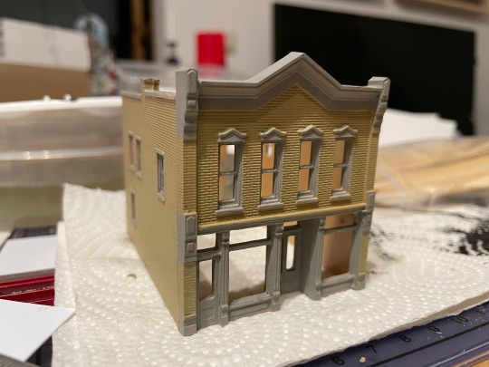
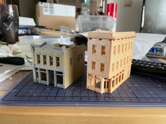

More model railroad content! I’m working on a new T-Trak module which will represent a small american town, and I’ve started by building the houses. None of them are complete yet, but I like how they turned out so far.
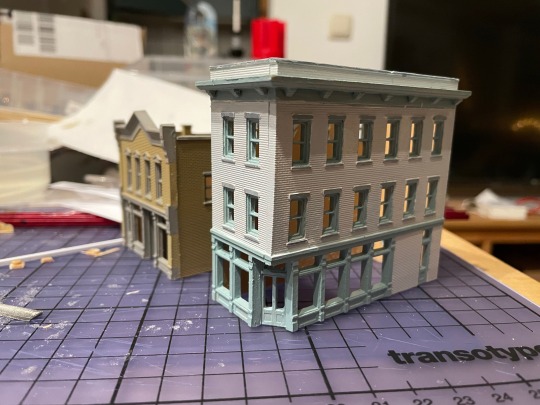
The first images are two kits by Woodlands Scenics, under their DPM brand. I’m not really impressed with these kits, since you have to file down parts of the walls and they lack such niceties as, I don’t know, roofs. They do include a piece of plastic; you have to cut out your own roof from that. I’ve shown the painting process of he second house in stages, so you get an idea what the default color of the plastic is. This really doesn’t work at all if not painted.
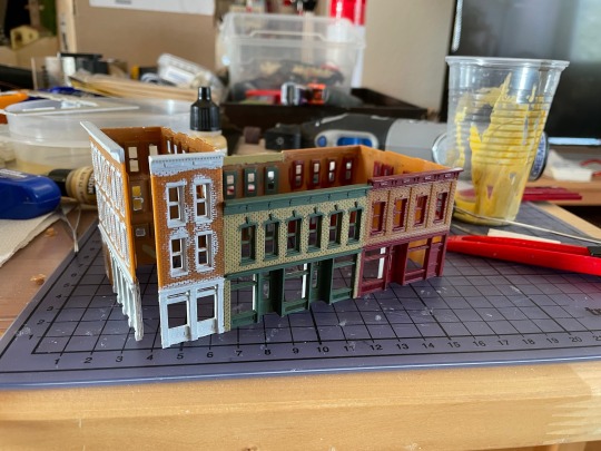
The final image is an integrated row of houses kit by Walther Cornerstone, in my opinion much better. Only the middle house there is painted yet; for the ones at the ends, I’ve only painted the windows, and will paint the bricks later. Of course it’s not fully assembled yet either.
All of them are made incredibly cheaply compared to german plastic model railroad house kits - even compared to communist-designed ones, and yes, I am speaking from experience here. In particular, the walls and windows are all just one big part, where german sets will have walls with holes, and the window frames will be another part in another color. You can build german kits without painting them at all, though over the years I’ve come to realise that you probably shouldn’t. It looks way, way better if you paint it, even though it is a bit of a pain. It gets better with practice. I’ve used mostly Revell Aqua Color paints here, about half the time straight out of the tub, and the other half mixed together to get a non-standard shade.
I did consider throwing in some coins or similar for scale, but then forgot. The cutting board does have a scale, though: The lines are all one centimetre apart (which means that the distance between the black lines is basically two inches).
The whole module is going to be a longer project. For one, I’m playing with the idea of putting some interior in at least some of these houses, which won’t be trivial in N scale. I’ll definitely put lights in them. The module is also going to have a level crossing, which means I need level crossing gates, and since there don’t seem to be good US level crossing gates commercially available, I guess I’ll have to create a 3D file and send it to Shapeways. And connect some cheap servo motors to make it work, and some LEDs to make it light up. And an Arduino (well, really just a bare ATmega328p) to control all of this and act as a DCC decoder. And so on…
For the record, I’m aiming for about 1950s to 1960s, though I also have a very beautiful Ford Model T from Artitec that’s definitely going to go on there. And I will, of course, absolutely run any and all trains I have along there, no matter from which era or country.
22 notes
·
View notes
Video
instagram
Looking to make your own CNC Machine? @tech_boys_toys has got you covered! - He used a small ACP sheet, wood or acrylic for the base and plotter bed. - For the X and Y axis he used two stepper motors and rails from DVD-CD drives, and for the Z axis he used a small servo motor. - The Arduino-based circuit is using the ATmega328 microcontroller and two L293 motor driver ICs. - DM for a link to the full video and tag someone who would like to build this! - - #arduino #cncmachining #dvdplayer #cdplayer #servo #acrylic #electronics #diyelectronics #stem #stemeducation #hobbylobby #maker #makersgonnamake #elementaryteacher #atmega #arduinoproject #engineering #drawingmachine #writingmachine #microcontroller #diyprojects #youtubechannel (at Busan, South Korea) https://www.instagram.com/p/B5ltkcPl3yq/?igshid=sue5e2qlq4ca
#arduino#cncmachining#dvdplayer#cdplayer#servo#acrylic#electronics#diyelectronics#stem#stemeducation#hobbylobby#maker#makersgonnamake#elementaryteacher#atmega#arduinoproject#engineering#drawingmachine#writingmachine#microcontroller#diyprojects#youtubechannel
2 notes
·
View notes
Text
CTEC607 #9
I researched how I could use hardware and Arduino to track the speed and direction of the record dish. I found a sensor called a rotary encoder, which counts incrementally as it rotates. They are often used in manufacturing to accurately control stepper motors/servos. There were various encoders, however an optical encoder seemed to be the best option.
I remember seeing a DJ mixer in the mechatronics lab which used spinning discs to mix. Fortunately, the optical sensor and code wheel were still intact, so I removed them with as little damage as possible.
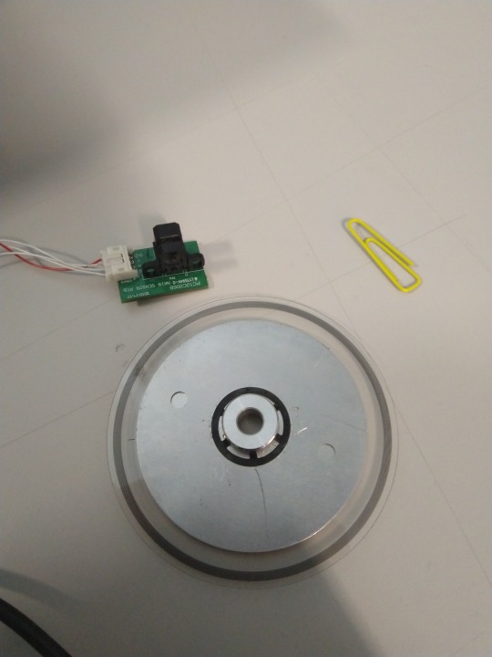
The encoder module has two sensors (A and B). The band on the code wheel is actually many small black lines, which the sensor counts. If the sensor counts A before B, the code wheel is spinning clockwise, if the sensor counts B before A, the code wheel is spinning anti-clockwise. The sensor operates on 5V power - perfect for an Arduino.
1 note
·
View note
Note
robot project's coming up soon but our tech teacher hasn't given us materials or any tips and we actually haven't even started soldering our arduino yet. in the maze we need to pick up a ball and drop it at a certain point but nooo we did NOT learn that type of coding/building ever. please help...?
Response From Fleur:
I did this project like 6 years ago but I remember it very clearly. Here’s the help I can give.
You want to create something similar to this: https://www.youtube.com/watch?v=EEbdo2WdTOI
How to build a simple freshman robot that runs: http://realtalk-tj.tumblr.com/post/172776232121/any-advice-on-the-robot-project-coding-time
“This is the code I used senior year to make two servos spin 360 degrees for a project of mine. This same code should work for your robot as well, though you should change the speed values to work for you (the numbers after the word “write”). You definitely have to play around a lot with the values that change the speed to see what works for you. If your code matches mine and your servo motors are not moving, I’d make sure everything is plugged in right. Make sure all your wires and power source are doing good and that you have things plugged into the right pin numbers (the pin number, in case you didn’t know, is after the word “attach”). Another idea is to try to hook your servo up to another computer if your current computer isn’t working. “
^From a previous answer

^here’s the code you’re going to need to make the servos spin 360 degrees.
Basic steps to building a freshman robot:
1) Make a box with four sides, a bottom, and an open top
2) Find wheels (CDs, lego wheels, whatever is allowed). Have four of them. Attach a servo of a size that will help your robot increase or decrease their speed to the wheel whether it be by glue or screwing it in somehow.
3) Drill holes in the side of the box near the bottom (plan this based on step 4). Push a rod through and somehow secure it so that it turns without sliding around a ton. You’re going to want one bit of rod per wheel. You’re going to want all your wheels to be able to turn individually. So I’d have four bits of rod, one for each wheel, and I would glue the wheel to the rod so that when the rod turns, your wheel turns with it.
4) Look at your gear and servo materials. Screw a small or big gear into your servo (depending on how fast you want the robot to go). Glue the servo to the bottom of your robot in a position that will allow that gear to spin your wheel when the servo moves by spinning the servo attached to your wheel.
5) Code things, hook up your arduino, and then toss your arduino in your robot box.
6) Attach the other things your specific tasks require (sensors, ball collector…etc)
I recommend front wheel drive with two individual servos powering two different wheels. You can make both of them do different things at the same time to turn (stop one while the other keeps going for a few seconds) through coding (ask the internet for help or upperclassmen or a tech teacher).
Pics of this approach:


^she was a pretty cute robot :)
Welp, that’s all I know :) Good luck! When in doubt ask the sophomores, they’re done all this before very recently
Response from Aurora:
I’m pretty sure you have Ms. Jones? She was like that last year and I heard she’s like that this year. We started (like actually started) the robot project sometime in mid/late April last year, and the deadline was supposed to be throughout May 10th - May 23rd. She ended up extending it to June 8 (a week before the last day of school). She also curved it 13 points, and the total robot project was 185 points. On top of that, she graded it pretty lightly. My robot barely moved and I literally just glued on my gears and stuff, and after the curve, I had about a 92% on the project. I was also about to end tech with a 92.4 but she bumped my grade up even though I didn’t ask her to, lol. So if you have her, don’t worry. My grade went up 10% on the last day of school when she put in all the grades. And even if you don’t have her, tech is just a small part of your time in high school, and in the end, it won’t strongly affect your overall performance or your GPA. Good luck :)
1 note
·
View note
Text
Servo motor arduino model solidworks

Servo motor arduino model solidworks for free#
Servo motor arduino model solidworks portable#
The 3D CAD model of the prosthetic hand cover can be seen in Fig. The solid model of prosthetic hand design can be exported into Sim Mechanics model for 3D animation and kinematics analysis purposes. SolidWorks is utilized because of easy to use and operate. The hand is designed using SolidWorks Computer Aided Design (CAD) software. It can be controlled through cloud or Wi-Fi. Its working can be made completely automatic and wireless. Light weight 3D printed modules/parts, makes it very easy for the amputees to carry it around with them. The whole work can completed under 15,000 rupees, which makes the robotic hand very affordable in comparisons to its present contemporary robotic hand proposal. It helps the people who have lost one of their hands or if it is paralysed. 3D printed prosthetics are further advantageous in that they are ideal for children and teenagers when one hand becomes too small, another can be readily printed in a larger size and reintegrated into the control system. Furthermore, the functionality and performance of consumer level robotic hands have advanced significantly in the past several years.ĭevelopments in the 3D printing industry have led to numerous designs of modelled hands from users all around the world, which the public can access online.
Servo motor arduino model solidworks portable#
Smartphone based controls are more portable and convenient than traditional myoelectric or motion sensing control systems. Therefore, developing a 3D printable hand that is easy to assemble and control in a nonprofessional setting with commonplace products such as Smartphones is vital for the average amputee. While people without any functional forearm muscles and even those with intact forearm muscles can use this approach,Įlectromyography can be difficult to use and is often imprecise. The most common control system in use is electromyography, a medical technique in which electrical signals from the remaining muscles in an amputees forearm are read by a device attached to the muscle and are mimicked by the prosthetic. This allows for less expensive, yet effective prosthetics to be available to modern consumers, with increased personalization for the user at a speed unachievable by conventional methods.īesides cost, another prevalent issue in high-level prosthetics is ease of control. Contrary to traditional prosthetics, which often cost tens of thousands of dollars1 and are usually unaffordable to many, these alternatives provide a relatively inexpensive option to the public.
Servo motor arduino model solidworks for free#
Online open source development has allowed for printable hand models to be downloaded for free within minutes from websites such as Thingiverse, a free, open source 3D modelling site. With 3D printed prosthetics gaining popularity with the advent of consumer level 3D printers, practical applications of these prosthetics have also been increasing. The Robotic Hand is mounted over a movable platform which is controlled by another hand. It is basically an Arduino based Robotic Hand system which controls a Robotic Hand using keypad using a, small and low-cost, micro switches. The system design is has 3 parts namely: Keypad Part, Robotic Hand and Platform. This paper deals with the Design and Implementation of A Low Cost Prosthetic Hand using Servo Motors. The technology has its many useful applications in the field of robotics, surgical operations, humanoid robots, etc. The technology can also be helpful in very precise instrumentation workings like a doctor operating a patient by a robot without its own hands. The Arduino based human hand replication system is a system that can help and secure the human presence to be put under harmful situations such as radioactive and bio hazardous. Implementation of pick and place operation of the different object using these commands are discussed. The Robotic Hand has some independent commands for all the five fingers open and close, wrist up and down, base clockwise and counters clockwise, movement of bot, Pick and Place and Home position to move the fingers. The design of the system is based on a simple, flexible and minimal control strategy. In this paper we deal with the design and development of a Five Fingered Robotic Hand (FFRH) using Arduino board, keypad and servo motor. Well, this paper provides the buttons or joysticks to controlling the complete Robotic Hand by the users hand. P.D.A College of Engineering Kalaburagi Karnataka IndiaĬollege of Engineering Kalaburagi Karnataka IndiaĪbstractThe idea is to change the perception of remote controls for actuating manually operated Robotic-Hand. A Low Cost Prosthetic Hand using Arduino and Servo Motors
0 notes
Text
Can arduino be used to control a forward and reverse motor

#Can arduino be used to control a forward and reverse motor how to
#Can arduino be used to control a forward and reverse motor driver
#Can arduino be used to control a forward and reverse motor pro
Our priority is making something that works, so we are using rubber bands to fix the motor. The motor and driveshaft can be connected directly. Pic 4: Setting the pinion gear onto the LEGO gear We want to keep the motor as small as possible, so let’s keep trying! If you have a LEGO motor, that may work too. This is a DC motor, but there was an article about making a motor and a LEGO gear by yourself using a Pinion gear from Mini-4WD, so we will use this method to connect the motor with a LEGO gear. The steering part is done, so let’s go into the drive shaft. Pic 3: Steering parts (left: backside/right: without tires)Ĭreating the Drive Shaft for the Forward/Backward Movement Today, we want to keep it as small as possible, so here is what we made.
#Can arduino be used to control a forward and reverse motor how to
If you search “LEGO steering”, there are many pages showing how to mount a LEGO steering. So, today, let’s use LEGO blocks to fulfill “The body should be easy to build”. Let’s think about what we need for a steering system and try them out. I’d like to say, “We’re going to make a realistic one using a 3D printer!”, but at this point that is too difficult. Now that we have the circuit ready and that we are able to control the angle of the motor with a servo motor, let’s create the steering for the car. Next, let’s make it so that we can control it based on the input from the controller. In this example, we set the delay at (1500), so the steering and driveshaft will move every 1.5 seconds. Pic 2: Controlling a servo motor with Arduinoįigure 3: Arduino circuit for servo motor We will control the servo motor using this servo library. When using a servo motor with Arduino, there is a library of useful materials (set program with pre-made process). Let’s create a circuit to control the servo motor. The servo motor we will be using today can control the angle from 0 to 180. What Is a Servo Motor?Ī servo motor is like the other motors we’ve used before with an additional circuit that controls angles. If we use a DC motor, can we make it turn by 30 degrees to the right? Maybe we should rotate the motor for just a little bit and move the motor 30 degrees? Sounds pretty difficult. Let’s think about mounting the steering to make the car turn left and right. We can use the same idea to make the RC car go forward and backward. In the circuit in figure 2 (see article “ Use Arduino to Control a Motor Part 2“), we can rotate and reverse the motor by outputting signals from Arduino #9 and #10, one after the other. We went over forward/backward motor movement in the article “Use Arduino to Control a Motor Part 2”.
#Can arduino be used to control a forward and reverse motor driver
Going forward and backward using a motor driver First, we will design the heart of an RC car, the circuit for “Basic movements are forward, backward, and steering mount.” Today, we will learn about many new concepts. > If we use infrared or XBEE wireless module, it may be possible, but it will be quite difficult. Let’s think about making the battery small too. > The Arduino UNO is pretty big to begin with, so maybe we should use a different Arduino. > We can use LEGO blocks, so that it will be easily to modify it. > We need 2 motors, one for going forward and backward, and one for the steering. Now, let’s see what kind of technology we need to use to make these things possible… Basic movements are forward, backward, and steering mount.Deciding the Specs of the RC Carīefore we get started, let’s decide the overall specs for the RC car. We will go over how all these parts work and how to customize them using actual demonstrations. In other words, if you fulfill these functions, you can call it an RC car. Today, we will try to make the basic parts of an RC car by ourselves and study basics about electronic circuits, steering, and engine movements.įigure 1: Structure of a radio-controlled carįigure 1 shows a rough breakdown of the functions found in an RC car.
#Can arduino be used to control a forward and reverse motor pro
Today Electronic’s RecipeĪrduino Pro mini (Arduino Pro Mini 328 5V 16MHz)īox for AA batteries (series circuit for 4) Just like when we made the Stevenson Screen, we will decide the specs of the radio-controlled car before getting started. Today, we will look at the motor driver in more detail and make our own radio-controlled car using a motor driver. In the article “ Use Arduino to Control a Motor Part 2“, we went over how to use a motor driver.
0 notes
Text
Customize your coffee cups with the Mug-O-Matic!
In order to inspire the next generation of scientists and engineers, Michael Graham (AKA EngineerDog) has come up with a robot that automatically draws on coffee mugs with a marker—and potentially much more.
In its nominal configuration, the Mug-O-Matic is controlled by an Arduino Nano with a custom TinyCNC board, and uses a trio of small servo motors for cup plotting.
Additionally, the device can be reconfigured into a wide variety of robotic forms, and features 60+ compatible parts with which to do so.
Mug-O-Matic is a 3-axis drawing robot that can customize coffee mugs! This capable little robot can draw anything you want via manual control, Bluetooth, calculated algorithms, or even g-code. So you can enjoy your custom mug creation, then wipe it clean. You could make it totally different every day for a year, and not make the same thing twice!
Its little buddy, the Desktop Sentry, is a pan-tilt turret that guards your desk! Also controlled via joystick, Bluetooth, algorithms, or G-code, this device can automatically guard your space with a laser or a rubber band launcher, or be used for light writing.
The intent of this project is to produce fun and accessible educational tools. We want to encourage people to engage in tinkering and making things, because the creative process is a powerful way to learn.
youtube
If you’d like to get to work on your own Mug-O-Matic, more info can be found here, including a parts list for the build. It is also slated for a release on Crowd Supply, which will likely make things easier and less expensive if you’re willing to wait!
Customize your coffee cups with the Mug-O-Matic! was originally published on PlanetArduino
2 notes
·
View notes
Text
Project 2
I had some trouble coming up with an idea for this project, but eventually decided on combining the ultrasonic sensor and servo motor. I ended up creating a small experience centered around the idea of balance.
An ultrasonic sensor measures how far a person is. By moving away and towards the sensor a servo motor moves and arm back and forth. The goal is to balance a coin on the arm by just moving the arm with your body. In this way I tried to encompass the feeling of balancing something with your own body except the experience is now external. You no longer have direct control and have to try and use the arduino instead.
I figured the idea of balance was universal. Taking the idea a step further as a student you are trying to balance many things in your life, so my goal was to create a small reflection of that physically.
I had a few issues while working on this project. I see myself as more straightforward so creating a poetic experience did not come to me easily. I bounced around with a lot of different ideas, before landing on what I have now. I think in the end it does a good job of creating a poetic experience.
When building the system I had some issues with the ultrasonic sensor. For some reason I was not getting any input and ended up taking it apart multiple times trying to find the issue. Eventually I realized I was using the wrong resistor. After changing it out I was finally able to get a reading.
I also experimented with adding a capacitive sensor where the coin rests. My idea was to start and stop the experience if the coin is not on the arm. I tried using foil and some resistors to measure if the coin was placed on the arm, but I could never get the reading to be very accurate. The sensor would either think the coin is always there or never there and sometimes my hand or something else would trigger it. My final solution was to just slow the movement to make it easier to just place the coin. The variations in the ultrasonic sensor make the experience challenging enough still with the slower movement.
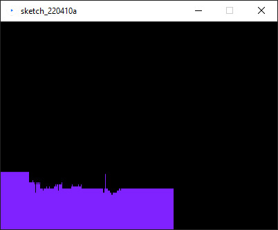
I also hooked my ultrasonic sensor up to processing to map the movement. This was probably the most challenging part. I went through multiple different projects to try and read arduino input on my PC. I finally landed on Processing as it worked right out the box and I was able to graph the users distance.
Video link: https://youtu.be/vOSW7lRcbXY


Arudino Code:
include
define echoPin 2
define trigPin 3
long duration; int distance; int pos = 0; Servo myservo; bool pause = true;
void setup() { pinMode(trigPin, OUTPUT); pinMode(echoPin, INPUT); Serial.begin(9600); myservo.attach(9); } void loop() { digitalWrite(trigPin, LOW); delayMicroseconds(2); digitalWrite(trigPin, HIGH); delayMicroseconds(10); digitalWrite(trigPin, LOW); duration = pulseIn(echoPin, HIGH); distance = duration * 0.034 / 2; //Serial.print("Distance: "); Serial.println(distance); if (distance > 18) { myservo.write(95); delay(1); } else if (distance < 5){ myservo.write(88); delay(1); } else { myservo.write(93); delay(10); }
}
Processing Code:
import processing.serial.*;
Serial myPort; // Create object from Serial class String val; // Data received from the serial port int xPos = 1; float inByte = 0; float prevInByte = 0;
void setup() { size(400, 300); String portName = Serial.list()[0]; myPort = new Serial(this, portName, 9600); background(0); }
void draw() { if ( myPort.available() > 0) { val = myPort.readStringUntil('\n'); if (val != null) { val = trim(val); inByte = float(val); println(inByte); inByte = map(inByte, 0, 1023, 0, height); } if(inByte < 100){ stroke(127, 34, 255); line(xPos, height, xPos, height - inByte * 10); prevInByte = inByte; } else { stroke(127, 34, 255); line(xPos, height, xPos, height - prevInByte * 10); }if (xPos >= width) { xPos = 0; background(0); } else { xPos++; }
} }
Sources: https://docs.arduino.cc/built-in-examples/communication/Graph
https://learn.sparkfun.com/tutorials/connecting-arduino-to-processing/all#introduction
0 notes
Video
tumblr
LEGO CLONE RAVE WITH ARDUINO
Using a servo motor, a few LED lights and some simple code, I was able to make a small party of one LEGO Clone Trooper. Maybe his friends will join him later.
Code:
#include <Servo.h>
Servo myservo; // create servo object to control a servo // twelve servo objects can be created on most boards
int pos = 0; // variable to store the servo position
void setup() { myservo.attach(9); // attaches the servo on pin 9 to the servo object pinMode(3, OUTPUT); //red pinMode(4, OUTPUT); //green pinMode(5, OUTPUT); //blue }
void loop() { for (pos = 0; pos <= 180; pos += 1) { // goes from 0 degrees to 180 degrees // in steps of 1 degree myservo.write(pos); // tell servo to go to position in variable 'pos' delay(1); // waits 1ms for the servo to reach the position } for (pos = 180; pos >= 0; pos -= 1) { // goes from 180 degrees to 0 degrees myservo.write(pos); // tell servo to go to position in variable 'pos' delay(1); // waits 1ms for the servo to reach the position } digitalWrite(4, HIGH); digitalWrite(3, HIGH); delay(200); digitalWrite(3, LOW); delay(100); digitalWrite(5, HIGH); delay(200); digitalWrite(5, LOW); delay(100);
}
1 note
·
View note