#UART-to-Ethernet
Explore tagged Tumblr posts
Visit Tumblr Blog
Explore Tumblr blogs with no restrictions, modern design and the best experience.
Last Seen Tumblr Blogs


Fun Fact
In 2020, 27% of US Tumblr users had an annual household income of over $100,000.
Text
Driving Smarter Microgrids with Forlinx Embedded!
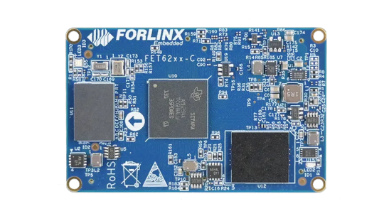
To support global carbon neutrality goals, microgrids are becoming a vital piece of the energy puzzle. The Forlinx AM62x-based FET6254-C SoM is revolutionizing microgrid coordination with:
⚡ Multi-core architecture (Cortex-A53 + Cortex-M4F) 🔄 Millisecond-level real-time control 🔌 Rich interfaces: CAN-FD, UART, TSN Ethernet 🌡️ Industrial-grade design: -40°C to +85°C

Perfect for PV, wind, storage & EV charging station coordination.
0 notes
Text

ESP32 WROVER Kit, Compatible with Arduino IDE The starter kit is based on the development board from esp32 wrover. It integrates with bluetooth and wireless.A powerful dev board for IOT module project development.ESP32-WROVER series is developed by Espressif Systems, below is key features and applications are summarized: I. ESP32 Wrover Specifications - Chip Architecture - Dual-core SoC (ESP32-D0WD or D0WD-V3) with a clock speed of 80–240 MHz (dynamic frequency scaling)13 - 520 KB integrated SRAM, expandable via external SPI RAM/Flash1 - Built-in 4–16 MB SPI Flash and 8 MB SPI PSRAM (depending on model, e.g., WROVER-B/E)37 - Wireless Connectivity - 2.4 GHz Wi-Fi (802.11 b/g/n) with up to 150 Mbps throughput36 - Dual-mode Bluetooth: Classic (BT) and Low Energy (BLE)36 - Peripherals & Interfaces - SPI, I2C, UART, SDIO, Ethernet interfaces3 - Support for capacitive touch, Hall effect sensors, PWM outputs37 II. ESP32 Wrover Kit Development Environment & Tools - Programming Frameworks - Official ESP-IDF framework (FreeRTOS + LwIP stack), C/C++-based16 - Arduino IDE compatibility via ESP32 board manager28 - Optional Python/C hybrid development using Zerynth Studio5 - Hardware Debugging Tips - Use 5V power for camera modules (3.3V may cause image instability)2 - Adjust SPI pin definitions (e.g., SCK=14, MISO=12) based on hardware layout4 III. ESP32 Devkit Typical Applications - IoT Devices - Sensor networks, smart home controllers with ultra-low-power modes (sleep current Read the full article
0 notes
Text
E5908 module RJ45 interface communication
How to achieve communication with the E5908 module RJ45, a brief introduction to help you take the next step
Introduction to the module and interface E5908 is an Ethernet communication module with a built-in TCP/IP protocol stack. It supports direct communication with an Ethernet switch or router through the RJ45 interface. The main control MCU can interact with the module through UART (AT command) or SPI/SDIO (depending on the module description).
Hardware connection (RJ45 interface) RJ45 interface (with magnetic transformer): The module's onboard RJ45 interface has an integrated magnetic transformer and can be plugged into a standard network cable without an external transformer. Power and ground: VCC (3.3V/5V) -> module VCC, GND -> module GND. UART connection: MCU_TX -> module UART_RX, MCU_RX -> module UART_TX Reset pin: connected to the MCU GPIO for module hardware reset. Decoupling capacitors: Add 10µF and 0.1µF decoupling capacitors to the module power pins to ensure stable power supply.
Network configuration:
DHCP: AT+NETMODE=DHCP returns +IP:...; Static IP: AT+NETMODE=STATIC,<IP>,<Mask>,<Gateway>. Establish socket: TCP client: AT+TCPSTART="<IP>",<Port>; TCP server: AT+TCPLISTEN=<Port>; UDP: AT+UDPSTART="<IP>",<Port>.
Data sending and receiving: Sending: AT+TCPSEND=<Len> → module prompts > → sending data; Receiving: module serial port pushes +TCP:RECV,..., followed by data.
Typical C code example:
#define UARThuart1 bool at_send(const char *cmd, const char *exp, uint32_t to) {...} void net_init(void) { //reset HAL_GPIO_WritePin(RESET_GPIO_Port, RESET_Pin, GPIO_PIN_RESET); HAL_Delay(50); HAL_GPIO_WritePin(RESET_GPIO_Port, RESET_Pin, GPIO_PIN_SET); HAL_Delay(200); at_send("AT+NETMODE=DHCP", "OK", 2000); } void tcp_client(void) { at_send("AT+TCPSTART=\"192.168.1.50\",8000", "CONNECT", 5000); at_send("AT+TCPSEND=5", ">", 2000); HAL_UART_Transmit(&UART, (uint8_t*)"hello", 5, 100); at_send("", "SENDOK", 2000); at_send("AT+TCPSTOP", "CLOSED", 3000); }
If you want to know more detailed solutions, please read this article: E5908 module Ethernet communication implementation solution
1 note
·
View note
Text
What are the main communication protocols in embedded systems?
Embedded systems rely on various communication protocols to enable efficient data transfer between components, microcontrollers, sensors, and external devices. These protocols can be broadly categorized into serial, parallel, wired, and wireless communication protocols.
UART (Universal Asynchronous Receiver-Transmitter) – A widely used serial communication protocol that facilitates full-duplex data exchange between embedded devices. It requires minimal hardware and is commonly used in debugging and low-speed data transfer applications.
SPI (Serial Peripheral Interface) – A high-speed, full-duplex protocol used for short-distance communication between a microcontroller and peripherals such as sensors, displays, and memory devices. It follows a master-slave architecture and is widely used in real-time embedded applications.
I2C (Inter-Integrated Circuit) – A multi-slave, half-duplex serial communication protocol designed for communication between multiple ICs using only two wires: SDA (data line) and SCL (clock line). It is highly efficient for low-speed applications and is commonly used in sensor integration.
CAN (Controller Area Network) – A robust, message-based protocol widely used in automotive and industrial applications. CAN allows multiple nodes to communicate efficiently without requiring a host computer. It ensures data integrity using error detection and correction mechanisms.
Ethernet – A widely adopted wired communication protocol that enables high-speed data transfer in embedded applications, especially in industrial automation and IoT systems. It supports networking capabilities for remote monitoring and control.
Bluetooth & Wi-Fi – These wireless protocols are essential for modern embedded systems, enabling connectivity in consumer electronics, IoT devices, and smart home applications. Bluetooth is preferred for short-range, low-power communication, while Wi-Fi offers high-speed data exchange over long distances.
Understanding these protocols is crucial for designing efficient embedded solutions. If you want to gain hands-on experience and expertise in these protocols, consider enrolling in an embedded system certification course.
0 notes
Text
Chatgpt computer communication design
Designing a computer circuit where two computers communicate with each other and "teach themselves" using an Arduino board involves a combination of hardware setup and software programming. Here’s a general guide to get you started:
1. Basic Concept
Two Computers (PCs or Microcontrollers): These are the two devices that will communicate and learn from each other. Each will run a program for self-learning.
Arduino Board: The Arduino will facilitate the communication between the two computers and control the process. It could also be part of the system performing calculations or simulations.
Communication Protocol: The two computers will need to communicate with each other. For simplicity, we can use serial communication (UART) or I2C with the Arduino acting as the intermediary.
2. Hardware Components
Arduino Board (e.g., Arduino Uno, Nano, or Mega)
Two Computers (PCs or other microcontrollers, like Raspberry Pi or other Arduino boards)
Communication Module: If you are using something like a Raspberry Pi or another microcontroller, you might need USB-to-Serial adapters or Bluetooth/Wi-Fi modules (e.g., ESP8266/ESP32, HC-05).
Power Supply: Proper power sources for the Arduino and computers.
Cables: USB, serial cables, or jumper wires for communication.
3. Circuit Design
Here is a high-level overview of the connections between the Arduino and the two computers.
Arduino and PC1 (Computer 1):
Connect the Arduino to PC1 via USB or UART communication pins (TX/RX pins if using serial).
Arduino and PC2 (Computer 2):
If you are using a second microcontroller (like another Arduino or a Raspberry Pi), connect them to the Arduino board using a communication protocol (e.g., I2C or UART).
The two computers could either communicate directly over a network (like Ethernet or Wi-Fi) or through serial communication.
For this example, let’s assume you are using UART for communication between the Arduino and both computers. You can use the TX/RX pins on the Arduino and connect them to the USB-to-Serial adapters connected to each computer.
4. Software Design
The software should allow the computers to "teach themselves," which likely means implementing some form of machine learning or pattern recognition. For simplicity, let’s outline how you could set up communication, with the learning part handled on the computers.
Arduino Code: The Arduino will act as the middleman for the communication. It will receive data from one computer, send it to the other, and also handle basic processing or simulation. It can be programmed to send responses or instructions back to the computers.
// Simple Arduino code for UART communication void setup() { Serial.begin(9600); // Start the serial communication at 9600 baud } void loop() { if (Serial.available()) { char incomingByte = Serial.read(); // Read incoming byte Serial.print("Received: "); Serial.println(incomingByte); // Send back the received byte } }
Computer 1 and Computer 2 Code: Each computer should run a program that will send data to the Arduino and receive responses. This could be a simple Python script or C++ program for serial communication.
Example Python Script: Here’s a basic Python script that can run on each computer. This script will send data to the Arduino and read the response back.import serial import time # Open serial port (make sure to change COM port for your system) ser = serial.Serial('COM3', 9600) # Change COM port as needed time.sleep(2) # Wait for the serial connection to initialize # Send data to Arduino ser.write(b'Hello Arduino!\n') # Read response while True: if ser.in_waiting > 0: response = ser.readline().decode('utf-8').strip() print(f"Arduino says: {response}") break ser.close()
This Python script could run on Computer 1, while a similar script runs on Computer 2. Both will send messages to the Arduino and receive feedback.
5. Self-Learning Simulation
To simulate the "self-teaching" aspect, each computer can use machine learning algorithms. You could start with something simple like linear regression or a decision tree. The computers could send random data points to each other and exchange feedback on whether the predictions made by each other are correct.
Computer 1 could generate a random dataset and send it to Computer 2.
Computer 2 processes the data, makes predictions, and sends the feedback back.
Computer 1 uses this feedback to adjust its learning algorithm (e.g., adjust weights in a simple linear regression model).
Example of a Simple Learning Process: Each computer could adjust its internal model based on the received feedback, similar to how a neural network or other machine learning models learn. The Arduino could be involved in simple processing tasks or sending acknowledgment signals when certain thresholds are reached (e.g., "success" or "failure").
6. Scaling Up
If you want to scale up the project to involve more complex learning or higher levels of interaction, you could use a more advanced platform such as a Raspberry Pi or ESP32/ESP8266 for networking and faster processing, where each computer uses a machine learning library (like TensorFlow Lite or scikit-learn).
7. Final Setup
Computer 1 and Computer 2 run machine learning algorithms that adjust based on feedback.
Arduino manages data flow between the computers and possibly performs basic learning tasks like adjusting variables or sending commands.
The entire system simulates a network where two computers are learning from each other.
This is a high-level overview, and there are many ways to implement it depending on the complexity of the communication and learning algorithm you want to achieve. Would you like to dive deeper into any specific area or need more detailed code for the project?
Creating two PCs from scratch using Arduino boards is an interesting challenge, but it's important to note that a full-fledged personal computer involves much more complexity than an Arduino is capable of. However, you can certainly simulate basic "PC-like" behavior using Arduino boards, where each "PC" would be a microcontroller (Arduino) with some level of functionality, communication, and processing.
High-Level Concept
Each Arduino board would act as a basic computing unit (like a simplified "PC"), running simple programs, processing input, and communicating with each other. While these "PCs" won't have the advanced features of a real computer (like an OS, GUI, or complex processing power), they can serve as learning devices or communication nodes in a network.
To make two PCs communicate with each other using an Arduino board, the Arduino acts as an intermediary. The Arduino will handle the communication between the two PCs, either via a serial connection (UART), I2C, or wireless communication (e.g., Bluetooth/Wi-Fi). Below is a guide on how to set up such a system:
1. Hardware Setup
Here, I'll describe a setup where two PCs communicate via an Arduino board using serial communication (UART). The Arduino will act as a mediator, forwarding messages between the two computers.
Components Needed:
Arduino board (e.g., Arduino Uno, Nano, Mega)
2 PCs (PC1 and PC2)
USB-to-Serial adapters (if using UART)
Jumper wires (if using direct communication between Arduino and PC)
Connections:
PC1 <-> Arduino: The first PC will communicate with the Arduino using its USB port (acting as a serial port).
PC2 <-> Arduino: The second PC will communicate via another USB-to-Serial adapter or possibly the second USB port of the Arduino (if the Arduino model supports multiple serial connections, e.g., Mega).
In simpler terms:
Arduino will be connected via USB to PC1.
PC2 will be connected to Arduino's serial pins (TX/RX) or using a USB-to-Serial adapter.
2. Arduino Code
The Arduino will need to read from one serial port (PC1) and forward the data to another serial port (PC2) and vice versa. The following is a simple Arduino sketch for this task.// Arduino code for mediating between two PCs void setup() { // Start serial communication with both computers Serial.begin(9600); // For communication with PC1 Serial1.begin(9600); // For communication with PC2 (if using Arduino Mega or another board with multiple serial ports) } void loop() { // Check if data is available from PC1 (connected to Serial) if (Serial.available() > 0) { char dataFromPC1 = Serial.read(); // Read data from PC1 Serial1.write(dataFromPC1); // Send data to PC2 (connected to Serial1) } // Check if data is available from PC2 (connected to Serial1) if (Serial1.available() > 0) { char dataFromPC2 = Serial1.read(); // Read data from PC2 Serial.write(dataFromPC2); // Send data to PC1 (connected to Serial) } }
Explanation of the Code:
Serial.begin(9600): Initializes communication with PC1.
Serial1.begin(9600): Initializes communication with PC2. (Note: Only available on boards with multiple UARTs like Arduino Mega, if using an Arduino Uno, you’ll need a USB-to-Serial adapter for PC2).
Serial.read(): Reads data from one serial port.
Serial.write(): Sends data to the other serial port.
3. Software on the PCs
On each of the two PCs, you will run a program that communicates with the Arduino via a serial connection. You can use Python to interface with the Arduino. Here’s a simple Python example that reads data from the Arduino and sends data back.
Python Code for PC1:
import serial import time # Connect to Arduino via serial port (Adjust the port name as needed) ser = serial.Serial('COM3', 9600) # Replace 'COM3' with your Arduino's port time.sleep(2) # Wait for the serial connection to establish # Send data to Arduino (which will forward to PC2) ser.write(b'Hello from PC1!\n') # Read data from Arduino (which is coming from PC2) while True: if ser.in_waiting > 0: response = ser.readline().decode('utf-8').strip() print(f"Received from PC2: {response}") break ser.close()
Python Code for PC2:
import serial import time # Connect to Arduino via serial port (Adjust the port name as needed) ser = serial.Serial('COM4', 9600) # Replace 'COM4' with your Arduino's port time.sleep(2) # Wait for the serial connection to establish # Read data from Arduino (which is coming from PC1) while True: if ser.in_waiting > 0: message = ser.readline().decode('utf-8').strip() print(f"Received from PC1: {message}") # Send data back to Arduino (which will forward to PC1) ser.write(b'Hello from PC2!\n') break ser.close()
4. Explanation of the PC Software:
Python serial library: Used to open a serial connection to the Arduino.
ser.write(): Sends data from PC1 or PC2 to the Arduino.
ser.readline(): Reads incoming data from the Arduino, which is forwarded from the other PC.
Time Delays: time.sleep(2) ensures that the serial connection is established before communication begins.
5. Communication Flow
PC1 sends a message (e.g., "Hello from PC1") to the Arduino.
The Arduino forwards the message to PC2.
PC2 receives the message, processes it, and sends a response back to the Arduino (e.g., "Hello from PC2").
The Arduino forwards the message back to PC1.
6. Adjusting for More Complex Setups
If you are using an Arduino Uno (which has only one serial port), you’ll need an additional USB-to-Serial adapter to handle communication with both PCs. Alternatively, you can use an Arduino Mega, which has multiple serial ports (like Serial, Serial1, Serial2, etc.).
For the Arduino Mega, you can use Serial for PC1 and Serial1 for PC2, as shown in the code above.
For PC2, you might need a USB-to-Serial adapter if you're not using an Arduino Mega.
7. Next Steps
To make the setup more advanced, you can:
Add error handling and retry mechanisms for more robust communication.
Implement data processing algorithms to simulate machine learning (e.g., a simple model for each PC that "learns" from the data it receives).
Use wireless communication like Bluetooth or Wi-Fi if you don't want to rely on USB connections.
Would you like to explore how to expand this further or add more complexity to the system? Let me know!
Here’s how you might approach creating two Arduino-based "PCs" from scratch:
1. Basic Requirements and Constraints
You’re working with Arduino boards, which are microcontrollers with limited processing power, memory, and storage compared to a real PC. The Arduino can run basic programs, perform calculations, and communicate with other devices, but it cannot run complex software like a PC.
To simulate PCs, you'll need:
Arduino microcontroller boards (e.g., Arduino Uno, Nano, Mega, etc.)
Inputs/outputs (e.g., buttons, LEDs, displays)
Communication method between the two Arduinos (e.g., UART serial, I2C, or even wireless)
Storage (limited, but can use EEPROM or SD card modules)
Basic display (e.g., an LCD or LED screen for output)
2. Building the Two "PCs" with Arduino
Each Arduino board will act as one "PC." Here’s how you can conceptualize the setup:
Arduino 1 (PC1): Will handle user input and perform computations.
Arduino 2 (PC2): Will also handle user input and perform computations. It will communicate with PC1 to share or exchange data.
The communication between the two PCs can be done using serial communication (UART) or I2C.
3. Basic Hardware Setup for Each PC
Each "PC" could have:
Buttons or switches to simulate input (e.g., user input or commands).
LCD or 7-segment display for output (or use an LED to indicate activity).
Communication interface to talk to the other PC (e.g., UART or I2C).
SD card or EEPROM to simulate storage.
Components Needed:
2 Arduino boards (e.g., Arduino Uno or Nano)
1 LCD display (16x2 or 20x4 for basic text output)
2 push buttons (to simulate input)
2 LEDs (to indicate some activity or status)
2 USB-to-Serial adapters (if using UART communication between PCs)
1 I2C or UART communication method
1 SD card module (optional for storage simulation)
4. Software Design for the "PCs"
Each Arduino PC will need a program to read inputs, perform some basic computation, and send/receive data to/from the other PC. Here’s a simple breakdown of the software for each Arduino:
Arduino PC1 (PC1 Sketch)
This sketch allows PC1 to process input (button presses), perform simple calculations, and send/receive data from PC2.#include <Wire.h> // For I2C communication (if using I2C) #include <LiquidCrystal_I2C.h> // For LCD display // Initialize the LCD (change pin numbers according to your setup) LiquidCrystal_I2C lcd(0x27, 16, 2); // Input and output pins int buttonPin = 7; // Pin for button input int ledPin = 13; // Pin for LED output void setup() { // Start communication Wire.begin(); // Start I2C communication if using I2C lcd.begin(16, 2); pinMode(buttonPin, INPUT); pinMode(ledPin, OUTPUT); lcd.print("PC1: Ready"); delay(2000); // Wait for 2 seconds } void loop() { int buttonState = digitalRead(buttonPin); // Read button state if (buttonState == HIGH) { // If button is pressed digitalWrite(ledPin, HIGH); // Turn on LED lcd.clear(); lcd.print("Button Pressed"); // Send data to PC2 (via I2C or serial) Wire.beginTransmission(8); // 8 is the I2C address of PC2 Wire.write("PC1: Button Pressed"); Wire.endTransmission(); } else { digitalWrite(ledPin, LOW); // Turn off LED } delay(100); // Small delay to avoid bouncing }
Arduino PC2 (PC2 Sketch)
This sketch for PC2 will receive data from PC1 and display it on the LCD, simulating output.#include <Wire.h> // For I2C communication (if using I2C) #include <LiquidCrystal_I2C.h> // For LCD display LiquidCrystal_I2C lcd(0x27, 16, 2); // LCD setup void setup() { Wire.begin(8); // Set PC2's I2C address to 8 Wire.onReceive(receiveEvent); // Define the event handler for receiving data lcd.begin(16, 2); // Start the LCD display lcd.print("PC2: Ready"); } void loop() { // Main loop does nothing, waiting for incoming data } void receiveEvent(int bytes) { String message = ""; // Initialize an empty string for the message while (Wire.available()) { message += (char)Wire.read(); // Read each byte and convert to character } // Display the received message on LCD lcd.clear(); lcd.print("PC2: "); lcd.print(message); // Print received message on LCD }
5. How They Communicate:
I2C Communication: In this setup, PC1 sends a message to PC2 using I2C. This allows you to connect the two Arduinos with just two wires (SDA, SCL) and share data.
Serial Communication (UART): Alternatively, if you're using UART (Serial) communication, PC1 sends data to PC2 via the Arduino’s TX/RX pins and vice versa.
6. Adding Storage (Optional)
To simulate storage, you can attach an SD card module to the Arduino. The Arduino can read/write simple text files or store computational results on the SD card.
Example of using an SD card module on PC1:#include <SPI.h> #include <SD.h> File myFile; void setup() { Serial.begin(9600); if (!SD.begin(4)) { Serial.println("SD card initialization failed!"); return; } myFile = SD.open("log.txt", FILE_WRITE); if (myFile) { myFile.println("PC1: Data Log"); myFile.close(); } else { Serial.println("Error opening log.txt"); } } void loop() { // Example of logging data continuously myFile = SD.open("log.txt", FILE_WRITE); if (myFile) { myFile.println("New Data Recorded"); myFile.close(); } delay(1000); // Wait for 1 second }
7. Expanding the "PCs"
You can add more features to each Arduino "PC," such as:
User input: Keyboard or mouse emulation.
Network Communication: Use Wi-Fi or Ethernet modules (like ESP8266 or Ethernet shield) to allow the two PCs to communicate over a network.
Processing: Implement simple algorithms or calculations on each Arduino to make them more like basic computers.
8. Limitations
Remember that an Arduino board is not a real PC, and it has significant limitations:
Limited processing power and memory.
No operating system or advanced software.
Minimal input/output capabilities.
But it is still a great way to learn about the basics of computer-like behavior, communication, and microcontroller programming.
Conclusion
While building a full-fledged PC using Arduino isn’t feasible, you can create two basic "PC-like" systems by using Arduino boards to simulate basic functionality such as processing, input/output, communication, and storage. This setup is a great way to learn about how computers work at a fundamental level, as well as how data is shared and processed between multiple devices.
Would you like to explore any specific part of the project further or need help with something else?
0 notes
Text
Cấu trúc của hệ thống nhúng?
Hệ thống nhúng có thể được chia thành bốn thành phần chính:
Bộ Vi Xử Lý (Processor)
🔹 Vi điều khiển (Microcontroller - MCU): 🔹 Vi xử lý (Microprocessor - MPU): 🔹 FPGA (Field Programmable Gate Array): 2. Bộ Nhớ (Memory)
🔹 RAM (Random Access Memory): Lưu trữ dữ liệu tạm thời khi hệ thống hoạt động. 🔹 ROM (Read-Only Memory): Chứa phần mềm nhúng (firmware) không thay đổi. 🔹 Flash Memory: Lưu trữ dữ liệu không bị mất khi mất điện (ví dụ: thẻ SD, EEPROM).
3. Thiết Bị Ngoại Vi (Peripheral Devices)
🔹 Cảm biến (Sensors): Thu thập dữ liệu từ môi trường (nhiệt độ, áp suất, gia tốc, ánh sáng,...). 🔹 Bộ truyền động (Actuators): Điều khiển cơ cấu chấp hành như motor, servo, van, relay. 🔹 Giao tiếp I/O (Input/Output Interfaces): UART, SPI, I2C, CAN, USB, Ethernet, Wi-Fi, Bluetooth
4. Phần Mềm Nhúng (Embedded Software)
🔹 Firmware: Chương trình điều khiển phần cứng, chạy trực tiếp trên vi điều khiển. 🔹 Hệ điều hành nhúng (RTOS - Real-Time Operating System): Quản lý tác vụ trong hệ thống phức tạp, đảm bảo thời gian thực. Ví dụ: FreeRTOS, VxWorks, Zephyr. 🔹 Ứng dụng nhúng (Embedded Application Software): Các thuật toán điều khiển, xử lý tín hiệu, AI.

0 notes
Text
What are the key components of an embedded system?
Key Components of an Embedded System
An embedded system is a specialized computing system designed to perform dedicated tasks within a larger system. It is typically built to be highly efficient, reliable, and optimized for specific functions. Here are the key components of an embedded system:
1. Microcontroller/Microprocessor: The central unit of an embedded system, the microcontroller (or microprocessor), processes data and executes instructions. It typically includes a CPU, memory, and input/output interfaces, all integrated on a single chip. The microcontroller determines the system's speed, power consumption, and functionality.
2. Memory: Embedded systems often use different types of memory, such as ROM (Read-Only Memory) and RAM (Random Access Memory). ROM stores firmware and software, while RAM is used for temporary data storage during operations. Flash memory is also common, providing non-volatile storage for the system's data.
3. Sensors and Actuators: Sensors collect real-world data, such as temperature, pressure, or motion, while actuators convert signals into physical actions, like moving motors or turning on lights. These components allow embedded systems to interact with their environment and execute tasks based on input data.
4. Power Supply: Since embedded systems are often deployed in remote or portable environments, a reliable power supply is essential. Power management ensures that the system operates efficiently and can run on minimal power, extending battery life in portable applications.
5. Communication Interfaces: Embedded systems often require communication with other systems or networks. Communication interfaces such as UART, SPI, I2C, and Ethernet are used for data transfer between the embedded system and other devices.
6. Software/Firmware: The software or firmware controls the operation of the embedded system, instructing the hardware to perform specific tasks. It is usually optimized for performance and resource usage, ensuring the system works within its constraints.
To fully understand these components and their interaction, enrolling in an Embedded Systems Course can provide in-depth knowledge and hands-on experience in designing and programming embedded systems.
0 notes
Text

Top 10 Skills You’ll Learn in an Embedded System Development Course in India
Today, with advanced technology in every field, the world has taken a big step toward creating new industries and innovations. It is one of the most challenging and exciting fields, and it's worth investing in by enrolling in an embedded system development course in India. The knowledge and skills gained are useful for outstanding performance in various domains such as IoT, robotics, and automotive technology. Here, we look at the top 10 skills you would learn in an embedded system development course, including a fascinating project initiative, TechnosCOE.
1. Familiarity with Microcontrollers and Microprocessors
Microcontrollers and microprocessors are the foundation base for embedded systems. Courses include architecture, functioning, and programming, with hands-on experience in popular controllers such as Arduino, PIC, and ARM, which form the backbone of most embedded applications.
2. Programming Languages
One of the main emphases of an embedded system development course in India is acquiring skills in programming languages such as C and C++. These skills are essential to writing firmware and developing applications for embedded systems. It also makes some courses introduce Python for scripting and debugging purposes to improve a student's versatility.
3. Real-Time Operating Systems (RTOS)
The creation of efficient and reliable systems is based on the understanding of how RTOS works. These courses cover the principles of multitasking, scheduling, and inter-process communication. By mastering RTOS concepts, students can develop systems for industries such as telecommunications and healthcare.
4. Circuit Design and PCB Development
These contain custom circuitry designs and a printed circuit board (PCB). The knowledge gained from developing circuitry robust and efficient within Eagle and Altium Designer gives immense value toward the prototyping and product development phase.
5. Sensor integration and data acquisition
Modern embedded systems interact with the physical world through sensors. Courses teach students how to integrate sensors, process their data, and use it in meaningful ways. Applications include temperature monitoring, motion detection, and environmental sensing, among others.
6. IoT (Internet of Things) Development
IoT has changed the face of industries, and at the center of this change is the concept of embedded systems. Students are taught to design devices that are internet-enabled, which can talk to other devices, and perform analytics in real-time data. The same skill can be applied to smart home automation and industrial applications.
7. Embedded Linux
Training on Embedded Linux is generally a part of an embedded system development course in India. It is a highly versatile and widely used open-source software in the world of embedded systems. A student learns how to develop applications, configure the kernel, and build custom distributions for different types of devices.
8. Debugging and Testing Techniques
Debugging is a key tool in embedded system development. Students become experts in using tools like JTAG debuggers and oscilloscopes to identify and debug those issues. Techniques on testing address all the requirements for the performance and safety of the system.
9. Communication Protocols
Understanding communication protocols is very important to the embedded engineers. The curriculum covers some popular protocols such as I2C, SPI, UART, CAN, and Ethernet, which are usually used in applications such as car systems and automation in industrial places.
10. Project Management and Documentation
Beyond technical skills, students also learn project management techniques and documentation practices. These soft skills ensure that they can efficiently collaborate with teams, manage timelines, and maintain accurate records of their work.
Role of TechnosCOE in Embedded Learning
Most embedded system courses include real-world projects that allow students to apply their skills practically. TechnosCOE is one such project, an initiative designed to bridge the gap between theoretical knowledge and practical application. TechnosCOE offers students opportunities to work on cutting-edge projects involving IoT, robotics, and smart devices.
This initiative focuses on teamwork, innovation, and problem-solving, ensuring learners are industry-ready. Through the TechnosCOE, students are exposed to real-world challenges and learn how to apply embedded system principles to develop effective solutions.
Why Choose an Embedded System Development Course in India?
India is turning out to be a fast-growing hub for embedded technology. Industries like automotive, healthcare, and consumer electronics will have a vast number of opportunities. Embedded system development courses offered in India will ensure expert faculty members, state-of-the-art labs, and industrial collaborations. They also offer internship and placement support, which proves to be perfect for career growth.
Conclusion
The course on embedded system development course in India not only gives the students technical expertise but also prepares them for dynamic and rewarding careers. Mastering microcontrollers to developing IoT solutions, these skills are invaluable in today's technology-driven world. Initiatives like TechnosCOE further enhance the learning experience, making these courses a worthwhile investment for aspiring engineers.
0 notes
Text
Mastering Embedded Systems: A Comprehensive Online Course Overview
Embarking on the journey to master embedded systems can open doors to exciting career opportunities and allow you to contribute to innovative technologies shaping our world. With the convenience and flexibility of online learning, you can now access comprehensive courses that delve deep into the intricacies of embedded systems. In this blog, we'll provide an overview of what to expect from a comprehensive online course in embedded systems, guiding you through the path to mastering this dynamic field.
Understanding Embedded Systems
Before diving into the specifics of an online course, let's briefly recap what embedded systems are. Embedded systems are specialized computing systems designed to perform specific tasks within larger systems or devices. They are ubiquitous in modern technology, powering everything from smartphones and smart appliances to automobiles and industrial machinery.
The Importance of a Comprehensive Course
A comprehensive online course in embedded systems goes beyond surface-level knowledge, providing you with a deep understanding of the underlying principles and practical skills needed to excel in this field. Such a course covers a wide range of topics, including:
Embedded Hardware Design: Understanding the architecture and components of embedded systems, including microcontrollers, sensors, and actuators.
Microcontroller Programming: Learning programming languages such as C and assembly language to write code for embedded systems.
Real-Time Operating Systems (RTOS): Exploring the concepts of multitasking, scheduling, and resource management in real-time embedded systems.
Embedded Software Development: Developing software applications for embedded systems, including device drivers, firmware, and middleware.
Communication Protocols: Understanding protocols such as UART, SPI, I2C, Ethernet, and CAN bus for inter-device communication.
Embedded System Debugging and Testing: Learning techniques and tools for debugging, testing, and troubleshooting embedded systems.
Course Format and Delivery
A comprehensive online course in embedded systems typically offers a variety of learning resources and formats to cater to different learning styles. These may include:
Video Lectures: Engaging video lectures presented by experienced instructors, covering key concepts and practical demonstrations.
Interactive Tutorials: Hands-on tutorials and exercises to reinforce learning and apply theoretical concepts to real-world scenarios.
Practical Projects: Opportunities to work on real-world projects, designing and implementing embedded systems solutions from start to finish.
Quizzes and Assessments: Regular quizzes and assessments to gauge your understanding of the material and track your progress.
Discussion Forums: Online forums for asking questions, sharing insights, and collaborating with fellow students and instructors.
Instructor Expertise and Support
One of the key factors that distinguish a comprehensive online course is the expertise and support provided by the instructors. Look for courses taught by experienced professionals with a deep understanding of embedded systems and relevant industry experience. Instructors should be accessible and responsive, providing guidance and support throughout your learning journey.
Student Success and Testimonials
Before enrolling in an online course, take the time to research student success stories and testimonials. Look for reviews and testimonials from past students who have completed the course and achieved success in their careers. Positive feedback and success stories can provide valuable insights into the quality and effectiveness of the course.
Conclusion
Mastering embedded systems requires dedication, commitment, and access to comprehensive learning resources. With a comprehensive embedded systems course online, you can gain the knowledge, skills, and confidence needed to excel in this dynamic field. By choosing a course that covers a wide range of topics, offers diverse learning formats, is taught by experienced instructors, and has a track record of student success, you'll be well on your way to mastering embedded systems and unlocking endless possibilities in your career.
0 notes
Text
Navigating the Road: Automotive Embedded Systems Mastery
Course Overview:
This comprehensive course at Technoscripts is designed to equip students with the essential knowledge and practical skills needed to excel in the field of automotive embedded systems. Through a combination of theoretical lectures, hands-on lab sessions, and real-world projects, participants will delve deep into the intricacies of embedded systems technology as applied to automotive embedded system course applications.
Course Objectives:
Gain a thorough understanding of embedded systems architecture and design principles.
Learn the fundamentals of automotive electronics and their integration with embedded systems.
Explore real-time operating systems (RTOS) and their relevance in automotive embedded systems.
Master the programming languages commonly used in automotive embedded systems development, such as C and C++.
Acquire proficiency in hardware interfacing, sensor integration, and data acquisition techniques specific to automotive environments.
Understand vehicle network protocols like CAN, LIN, and FlexRay, and their significance in modern automotive systems.
Develop skills in debugging, testing, and troubleshooting embedded systems in automotive applications.
Explore advanced topics such as automotive cybersecurity, functional safety (ISO 26262), and autonomous vehicle technologies.
Gain hands-on experience through practical exercises, simulation tools, and industry-relevant projects.
10. Prepare for a successful career in automotive embedded systems engineering or related fields.
Course Curriculum:
Introduction to Embedded Systems
Basics of embedded systems
Embedded system architecture
Embedded hardware components
Automotive Electronics Fundamentals
Overview of automotive electronics
Sensors and actuators
Power management systems
Real-time Operating Systems (RTOS)
Introduction to RTOS
RTOS concepts and scheduling
RTOS implementation in automotive systems
Programming for Embedded Systems
C programming basics
Embedded C programming techniques
C++ for embedded systems
Hardware Interfacing and Integration
Peripheral interfaces (GPIO, UART, SPI, I2C)
Analog and digital sensor interfacing
Motor control and driver circuits
Automotive Communication Protocols
Controller Area Network (CAN)
Local Interconnect Network (LIN)
FlexRay and Ethernet
Embedded Systems Development Tools
Integrated Development Environments (IDEs)
Debugging techniques and tools
Simulation and modeling tools
Advanced Topics in Automotive Embedded Systems
Automotive cybersecurity
Functional safety (ISO 26262)
Autonomous vehicle technologies
Practical Projects and Case Studies
Hands-on lab sessions
Industry-relevant projects
Case studies from automotive industry leaders
Course Duration:
The course is designed to be completed over a period of X weeks/months, with both full-time and part-time study options available to cater to diverse learner needs.
Prerequisites:
Basic understanding of electronics and programming concepts is recommended.
Familiarity with the C programming language would be advantageous but not mandatory.
Certification:
Upon successful completion of the course, participants will receive a certificate from Technoscripts, affirming their mastery of automotive embedded systems.
Who Should Attend:
Electronics and electrical engineering students/professionals interested in automotive technology.
Automotive engineers looking to enhance their skills in embedded systems.
Professionals seeking career opportunities in automotive embedded systems development.
Conclusion:
Mastering Automotive Embedded Systems course at Technoscripts offers a unique opportunity to delve deep into the fascinating realm of automotive technology, equipping participants with the knowledge and skills needed to thrive in this dynamic industry. Join us on this transformative journey towards becoming a proficient automotive embedded systems engineer.

#automotiveembeddedsystemscourse#automotiveembeddedtestingcourse#automotiveembeddedinstitute#automotiveembeddedcourse#automotiveembeddedclasses#embeddedinstitute#embeddedclasses#embeddedcourse#embeddedtraining#embeddedsystemscoursepune
0 notes
Text
🚨 Prevent Electrical Fires Before They Start Did you know that up to 70% of electrical fires are preventable?

Forlinx Embedded presents a smart and efficient solution for electrical fire monitoring systems powered by the FET6254-C SoM.
With real-time monitoring, fast alerts, dual-core architecture, and industrial-grade stability, this solution is ideal for residential, commercial, and industrial applications.
✅ Real-time current, voltage & temperature monitoring ✅ Reliable alerts on overheating, short circuits & more ✅ Dual-core (A-core + M-core) for mission-critical stability ✅ Rich interfaces: CAN-FD, UART, Gigabit Ethernet, LVDS ✅ Designed for industrial environments

#Forlinx#EmbeddedSystems#ElectricalSafety#FirePrevention#IoT#SmartMonitoring#FET6254C#IndustrialControl
0 notes
Text
Top Skills Every Automotive Embedded Engineer Must Possess
Automotive Embedded engineering, the dynamic fusion of hardware and software, is rapidly evolving, fueling the demand for skilled professionals. As technology propels forward, the role of embedded engineers becomes increasingly pivotal in shaping cutting-edge solutions across diverse industries. In this comprehensive exploration, we uncover the top indispensable skills every embedded engineer should possess, delving into both technical competencies and non-technical skills that pave the way for a triumphant Embedded Career.
For more info https://neuailabs.com/
Responsibilities of an Embedded Engineer
Embedded engineers orchestrate the development of embedded systems, assuming critical roles in hardware and software design, firmware development, and rigorous testing. Their collaborative efforts with cross-functional teams ensure the reliability, performance, and compliance of embedded systems with project requirements.
Technical Competencies: The Foundation of Excellence
1. Knowledge of Hardware
In our Automotive Embedded Course, you will master digital and analog circuits, microcontrollers, microprocessors, and FPGAs. This profound understanding is the bedrock for crafting efficient and reliable hardware components.
2. Real-Time Operating Systems (RTOS)
Efficient system design demands familiarity with RTOSs like FreeRTOS, RTX, or μC/OS-II. These systems manage task scheduling and resource allocation, ensuring seamless operation.
3. Communication Protocols
Mastery of communication protocols such as SPI, I2C, UART, CAN, and Ethernet is imperative for establishing fluid communication between different components of an embedded system.
4. Debugging and Testing Tools
Embedded engineers wield tools like JTAG, Logic Analyzers, and oscilloscopes with finesse. Proficiency in these tools is non-negotiable for identifying and resolving hardware and software issues.
Non-Technical Skills for Embedded Engineers
In addition to technical competencies, non-technical skills are equally important for embedded engineers to excel in their careers. These skills include:
1. Teamwork and Collaboration
Embedded engineering projects often involve interdisciplinary teams where effective communication and collaboration are essential. Embedded engineers should be able to work well within a team, share knowledge, and incorporate feedback from team members.
2. Time Management and Prioritization
Embedded engineering projects often have strict deadlines. Embedded engineers must have strong time management skills to prioritize tasks effectively, meet project milestones, and deliver high-quality results on time.
3. Attention to Detail
Embedded systems are complex, and even minor errors can have significant consequences. Attention to detail is crucial for identifying and rectifying issues, and ensuring the reliability and performance of the system.
4. Creative Problem-Solving
Embedded engineers encounter various challenges during system development. The ability to think critically and creatively to solve these challenges is essential for success. They should be able to analyze problems from multiple perspectives and propose innovative solutions.
These non-technical skills complement the technical competencies of embedded engineers, allowing them to work effectively within teams and deliver successful projects.
Fundamental Abilities and Attributes
In addition to skills and competencies, specific fundamental abilities and attributes elevate an embedded engineer to new heights.
1. Analytical Skills
Strong analytical skills empower embedded engineers to dissect complex situations, identify potential issues, and make informed decisions.
2. Attention to Detail
Embedded systems demand precision and accuracy. Meticulous attention to detail guarantees the integrity and reliability of the system.
3. Adaptability
As technology evolves, adaptability becomes a cornerstone. Embedded engineers embrace change, staying updated and adjusting their skills and knowledge accordingly.
4. Patience
Embedded system development is a journey that demands patience and perseverance. Facing challenges and setbacks, embedded engineers approach problem-solving with iterative precision.
Enhancing Engineering Skills within the Embedded Systems Domain
To stay ahead in this dynamic field, embedded engineers must adopt proactive strategies.
1. Continuous Learning
Actively seek opportunities to learn and stay abreast of the latest technologies, industry trends, and best practices. Dive into technical literature, attend conferences, and absorb the wealth of knowledge available.
2. Personal Projects
Undertake personal projects to explore new technologies, experiment with different approaches, and gain hands-on experience. These projects not only enhance skills but also serve as a showcase of expertise.
3. Professional Development Courses
Enroll in relevant courses or certifications focusing on specific embedded systems areas. Structured learning builds a robust foundation, enhancing overall proficiency.
4. Networking and Mentorship
Engage with the embedded systems community through online forums, social media, and professional networking events. Forge connections with experienced professionals for valuable insights and guidance with our embedded systems career development classes.
Abilities Required for Future Embedded Engineers
As technology propels forward, embedded engineers must evolve, acquiring new skills and adapting to emerging trends.
1. Artificial Intelligence and Machine Learning
A solid understanding of AI and ML concepts is essential. Embedding these technologies into systems enables intelligent decision-making and autonomous functionality.
2. Security
With increased connectivity, security becomes paramount. Proficiency in designing secure systems and implementing encryption algorithms is crucial to thwart threats.
3. Internet of Things (IoT) Devices
The expanding IoT landscape demands skills in building devices, integrating sensors, and managing network communications for seamless connectivity.
4. Wireless Communications
Proficiency in wireless protocols like Wi-Fi, Bluetooth, and LoRaWAN is indispensable. Understanding the nuances of wireless communication ensures secure and efficient solutions.
For more info https://neuailabs.com/automotive-embedded/
Conclusion
In the intricate tapestry of embedded engineering courses, success is not a destination but a continuous journey. A fusion of technical skills, non-technical acumen, fundamental abilities, and a commitment to perpetual learning propels embedded engineering to thrive in this ever-evolving landscape with our automotive embedded courses. As guardians of innovation, embedded engineers shape the future, contributing to the advancement of technology. In the realm of embedded systems, mastery is not an option; it's the essence of excellence.

#automotive embedded course#embedded systems course#automotive embedded training#embedded systems course in pune#embedded classes in pune#neuailabs#futureofai
0 notes
Text
In the Beginning: The History and Evolution of Device Servers

Lantronix PremierWave EN dual band WiFi device server
In the beginning (well the 1980s), there were terminal servers. And they were good. These devices allowed for dozens of ‘dumb’ terminals to be connected to a mainframe or minicomputer over a single wired Ethernet connection. They were widely deployed at banks, automotive dealerships and insurance companies - anywhere a concentration of computer users was to be found. One of the main benefits was not having to run yet another cable all the way from the main computer to the new terminal location. As these terminal servers advanced, they allowed for another level of authentication to be implemented, via local username and password. Savvy administrators started finding ways to also connect printers to these servers and ultimately, terminal server designers added direct support for print queuing. This was a substantial timesaver, as now the printer could be placed near the user without a dedicated drop. Since some printers were installed remotely without associated terminals, it was a natural extension to create a terminal server dedicated to attaching printers to the network. With this, the print server was born.
With the explosive growth of microcontrollers in products, a plethora of equipment that had serial connectivity began to emerge. Asynchronous serial was a well-established means of communicating with a computer and with the addition of a UART and line driver, it became easy for a designer to allow a way to interface with their new products. The problem then was that serial only worked well over 50-100 feet, depending on data rate. Someone came up with the idea of using a terminal server to connect these products (alarm panels, industrial equipment, medical devices, etc.) to the network. Most of the available terminal servers had high port counts (16, 32) so it was rather expensive to use a terminal server on the shop floor to hook one or two machines to the network. Lantronix solved this problem by creating 1-, 2-, and 4-port ‘serial servers’ as they were first branded, later coining the term ‘device servers’.
Initially, device servers were external ‘box’ products consisting of a small plastic or metal enclosure, which contained the serial-to-Ethernet conversion circuitry, regulated power supply, led indicators, Ethernet connector (RJ45) and the requisite RS232 connectors. Over the years, these boxes have shrunk in size and added additional interface types, including RS422 and RS485. Originally, the software enabled basic serial-to-Ethernet conversion (often called ‘tunneling’). As technology advanced, the firmware became much more configurable and for some applications, became protocol-aware. This was important because if data was not properly packed into a TCP (network) packet, it could become fragmented when arriving at the other end of the connection. This fragmentation could cause timeouts and other bad behavior from products and software used to having a direct connection.
In the late 1990s, web servers were added to device servers, giving them a new way of being configured and for data presentation. At this time, OEM manufacturers inquired about embedding device server functionality onto their main boards. Small products specifically designed for being embedded were created. These dispensed with the power supply regulation and serial interface circuitry. They were ideal for integrating to a main board, requiring only logic level power and signals. True to device server technology, they handled all of the tasks associated with getting a machine on to the network. It made networking easy for an OEM. In 2002, Lantronix changed the face of embedded device servers when they came out with the ultra-miniature XPort. This was a complete serial-to-Ethernet device with web server in a standard sized RJ45 jack (about the size of two sugar cubes). Millions of these devices have been deployed worldwide.
The next logical step was to branch out to additional transport types including wireless 802.11. Both embedded and external device servers have been produced utilizing the ever improving 802.11 standards. 802.15.4 and Zigbee have also benefited from the creation of embedded modules.
While many additional customer interface standards have been created, asynchronous serial is still the most common way device servers are connected to equipment, both in embedded and external applications. More recently, SPI has become interesting for high-speed transfers from an OEM main board to an embedded device server, as well as 802.3 wired Ethernet (“bridging” to 802.11 wireless).
Where are device servers headed? Physical size reduction is always foremost on the list. Also having faster ways to interface to an embedded device (i.e. SPI, USB, etc) to improve overall bandwidth. It has been imperative to add additional compute power and memory resources for tackling increasingly complex encryption and authentication methods. This extra ‘horsepower’ has obviated the need for a main processor in some embedded applications. It’s funny to think that just eight years ago, a device server might be able to execute 30 million instructions per second. Now it is upwards of 400 million! Additional I/O capabilities allow a wider variety of sensors and other peripherals to be attached to a device server. And of course, keeping up with the latest standards in wired and wireless communications is a must. Device servers have come a long way, but the goal remains the same: Handle all communication tasks from A to Z, whether wired or wireless, and provide a very easy-to-implement solution that keeps the customer focused on their core business and gives them a huge time-to-market advantage.
0 notes
Text
NXP and Xiaomi Vela jointly build an IoT ecosystem to provide a powerful technology engine for the IoT development community
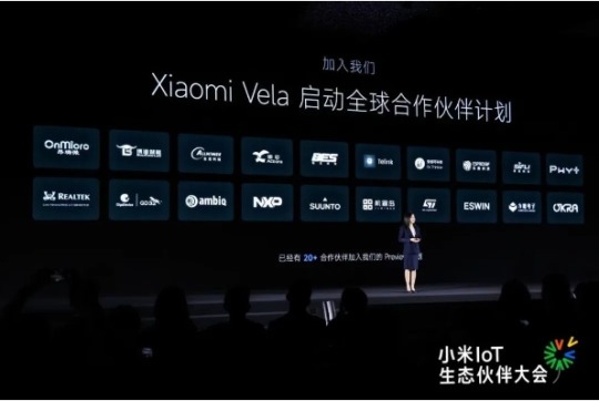
【Lansheng Technology News】Recently, at the 2023 Xiaomi IoT Ecological Partner Conference, NXP Semiconductors was invited to attend as an important partner of Xiaomi and demonstrated the powerful technical resource support provided to the Xiaomi Vela ecological community.
Xiaomi Vela is an embedded IoT software platform built on the open source real-time operating system NuttX and customized for consumer-grade IoT. It can provide a unified software platform on various IoT hardware, shielding the differences in underlying hardware. Through rich components and standardized software frameworks, it provides a unified software interface for upper-level device developers to open up fragmented things. Networked application scenarios greatly reduce the complexity of development and improve development efficiency.
As a global ecological partner of Xiaomi Vela, NXP is deeply involved in the construction of the ecosystem of this development community and has launched a series of technical resources. At this event, NXP highlighted the i.MX RT1060 EVK development kit.
NXP's i.MX RT1060 cross-border MCU is based on the 600MHz Arm Cortex-M7 core and has 1MB on-chip SRAM. It has strong real-time performance and high integration, and is suitable for various industrial and IoT applications. The i.MX RT1060 series provides 2D graphics, camera and various memory interfaces, as well as a wide range of connection interfaces, including UART, SPI, I2C, USB, 2 10/100M Ethernet interfaces and 3 CAN interfaces. Its other features for real-time applications include: high-speed GPIO, CAN-FD, and synchronous parallel NAND/NOR/PSRAM controller.
In addition, i.MX RT1060 has a 2D hardware graphics acceleration PXP module, 3 I2S interfaces for high-performance multi-channel audio, and supports LCD display controller (up to WXGA 1366 x 768). The i.MX RT1060 is available in 225BGA and 196BGA packages, providing greater flexibility with an extended temperature range of -40°C to 125°C.
The i.MX RT1060 series can be developed using NXP's official MCUXpresso tool chain, including SDK, IDE options, and security configuration and configuration tools, enabling rapid development and supporting various real-time operating systems (RTOS) such as FreeRTOS, Xiaomi Vela, Nuttx, Zephyr, etc. .
Xiaomi Vela is fully scalable from micro (8-bit) to mid-range embedded (64-bit) systems with a high degree of standards compliance, easy to port, fully open, highly real-time and powerful. i.MX RT1060 fully supports Xiaomi Vela. Currently supported drivers include ADC, CAN, eLCDIF, ENC, ENET, GPIO, I2S, PWM, SPI, UART and USB. It also supports Vela’s LVGL Demo and can be adapted to Xiaomi The upper component of Vela framework. This combination of soft and hard will provide a powerful technical engine for the development of the Xiaomi Vela ecological community.
Lansheng Technology Limited, which is a spot stock distributor of many well-known brands, we have price advantage of the first-hand spot channel, and have technical supports.
Our main brands: STMicroelectronics, Toshiba, Microchip, Vishay, Marvell, ON Semiconductor, AOS, DIODES, Murata, Samsung, Hyundai/Hynix, Xilinx, Micron, Infinone, Texas Instruments, ADI, Maxim Integrated, NXP, etc
To learn more about our products, services, and capabilities, please visit our website at http://www.lanshengic.com
0 notes
Text
Calibracion de osciloscopio guadalajara jalisco
Caracterización de elementos electrónicos: Deja evaluar y caracterizar componentes electrónicos, como transistores, diodos, condensadores y resistencias.
El calibracion de osciloscopio guadalajara jalisco puede ayudar a determinar las características y hábitos de estos elementos , como la contestación en frecuencia , la impedancia, la capacitancia y la inductancia.
Análisis de señales: Deja ver y analizar diferentes tipos de señales, como ondas senoidales, cuadradas, triangulares, pulsos, etcétera. Esto es útil para examinar características y propiedades de la señal, como amplitud, frecuencia , forma de onda, duración de los pulsos, distorsión, entre otros muchos.
Verificación de la señal de entrada/salida: El osciloscopio deja contrastar la calidad y las peculiaridades de las señales de entrada y salida de un instrumento eléctrico.
Por poner un ejemplo , si un instrumento no está exponiendo los valores aguardados , puedes utilizar el osciloscopio para analizar la manera de onda de la señal de entrada y verificar si está dentro de los factores correctos. De igual forma , puedes analizar la señal de salida para asegurarte de que se esté provocando apropiadamente.
Análisis de protocolos de comunicación: En apps de comunicaciones digitales, un osciloscopio guadalajara puede utilizarse para investigar y decodificar señales de protocolos como UART, I2C, SPI, CAN, Ethernet, entre otros muchos. Esto deja verificar la integridad de la comunicación, detectar errores y investigar el rendimiento de la transmisión de datos.
Control de calidad: En la fabricación de instrumentos eléctricos, el osciloscopio guadalajara se utiliza para efectuar pruebas de control de calidad. Deja evaluar la calidad de las señales generadas por los instrumentos y contrastar si cumplen con los estándares requeridos. Además de esto , se puede usar para identificar y solucionar problemas en los procesos de fabricación, como interferencias, estruendos o distorsión en las señales.
1 note
·
View note
Text
Uncovering the Force of the MSO5104: An Exhaustive Examination of the 100MHz Mixed Signal Oscilloscope
Introduction
In the domain of electronic testing and estimation instruments, the oscilloscope stands tall as an irreplaceable apparatus. It empowers designers, researchers, and specialists to envision and break down electronic waveforms with accuracy. Among a great many oscilloscopes accessible, the MSO5104 becomes the overwhelming focus as a solid and flexible instrument fit for taking care of mixed-signal applications with its wonderful 100MHz transmission capacity. This article expects to investigate the highlights, applications, and benefits of the MSO5104, revealing insight into why it is a favored decision for experts in different ventures.
Figuring out the MSO5104
The MSO5104 is a strong mixed-signal oscilloscope that joins the functionalities of a digital oscilloscope and a rationale analyzer. It is intended to give exact and nitty gritty estimations of both simple and digital signals, making it a flexible device for designers, researchers, and specialists working in different businesses.
Outline and Key Details:
The MSO5104 offers an exhaustive arrangement of highlights and details that add to its outstanding exhibition. It flaunts a 100MHz data transmission, which considers high-recurrence signal examination, and a testing pace of XGS/s (giga-tests each second), guaranteeing an exact catch of quick evolving waveforms. The oscilloscope is furnished with a huge high-goal variety show, which gives an unmistakable and nitty-gritty perspective on waveforms for examination. Furthermore, it offers a profound memory limit, empowering the catch and capacity of countless waveform tests for inside and out examination.
Equipment Elements:
The MSO5104 accompanies various simple and digital information channels, permitting clients to all the while interface and dissect a blend of simple and digital signals. This mixed-signal capacity is especially important while working with complex frameworks that include the two kinds of signals. The oscilloscope likewise upholds a scope of tests intended for various applications, guaranteeing exact and dependable estimations. The showcase and UI are intended to be easy to use and instinctive, empowering simple routes and control of the instrument's capabilities and settings. This guarantees a smooth client experience and a proficient work process.
Programming Abilities:
The MSO5104 is furnished with a wide cluster of programming highlights that improve signal examination and work with inside and out waveform assessment. It gives different underlying devices and capabilities for signal examination, for example, quick Fourier change (FFT) investigation, waveform math, and progressed setting off choices. These elements permit clients to separate significant experiences from complex waveforms, recognize peculiarities, and portray signal ways of behaving. Besides, the oscilloscope's rationale analyzer usefulness empowers the catch and investigation of digital signals, making it reasonable for investigating and troubleshooting digital frameworks. It upholds the disentangling and examination of famous sequential correspondence conventions, like I2C, SPI, UART, and CAN, working on the most common way of distinguishing and troubleshooting digital connection point issues.
Network and Mix:
The MSO5104 offers a scope of network choices, including USB, Ethernet, and GPIB interfaces. These choices empower consistent incorporation with different gadgets and work with information sharing and controllers. Clients can without much of a stretch interface the oscilloscope to a PC or organization, move caught waveforms for additional examination or capacity and control the instrument from a distance. This availability improves cooperation and empowers proficient information executives in both individual and group-based settings.
Applications:
The MSO5104 tracks down applications in a great many ventures and fields. In the simple signal examination, it is a priceless device for circuit configuration, testing, and improvement. Engineers working in power hardware, auto, aviation, and different ventures can depend on the oscilloscope's capacities to break down voltage and current waveforms, guaranteeing the effective plan and activity of electronic frameworks. In the digital signal examination, the MSO5104 is appropriate for implanted framework improvement, where the concurrent perception of simple and digital signals is urgent for troubleshooting and advancing framework execution. Its capacity to unravel and break down sequential correspondence conventions additionally streamlines the investigation and approval of digital points of interaction. Moreover, the MSO5104 is broadly utilized in instructive foundations for showing gadgets and signal examination and in research labs for exploring complex peculiarities and procuring information.
Uses of the MSO5104
The MSO5104, with its mixed-signal examination capacities and flexible elements, tracks down applications in many businesses and fields. We should investigate a portion of the critical utilizations of this oscilloscope:
Circuit Plan and Testing:
The MSO5104 is a significant apparatus for engineers associated with circuit plans and testing. It's high data transfer capacity and testing rate empower exact estimations of simple signals, guaranteeing a precise portrayal of circuit conduct. Architects can dissect voltage waveforms, current waveforms, and different signals to approve circuit execution, upgrade plans, and investigate issues.
Power Gadgets:
In the field of force hardware, the MSO5104 assumes a significant part. Engineers dealing with power circuits can utilize this oscilloscope to examine voltage and current waveforms, measure power factors, assess effectiveness, and research transient reactions. It empowers productive planning and improvement of force frameworks, like inverters, converters, and power supplies.
Auto and Aviation:
The MSO5104 tracks down applications in auto and aviation enterprises. It is utilized for examining simple signals in-vehicle frameworks, control frameworks, and aeronautics. Specialists can inspect different signals, including sensor yields, control signals, and correspondence conventions, to guarantee legitimate working, analyze blames, and improve framework execution.
Installed Frameworks Advancement:
The MSO5104's mixed-signal investigation capacities make it a significant resource for designers dealing with installed frameworks. It considers the concurrent perception of simple and digital signals, helping with investigating and upgrading framework execution. Designers can break down the cooperations among simple and digital parts, confirm timing connections, and distinguish expected issues in complex implanted frameworks.
Sequential Transport Examination:
The oscilloscope upholds the deciphering and examination of different sequential correspondence conventions, including I2C, SPI, UART, and CAN. This component improves the investigation and approval of digital points of interaction. Architects can screen transport exercises, catch and translate conventional explicit information, and analyze correspondence mistakes in gadgets like microcontrollers, sensors, and correspondence modules.
Training and Exploration:
The MSO5104 is broadly utilized in instructive establishments to show gadgets and signal examination. Its easy-to-understand point of interaction and extensive elements make it an optimal device for understudies to find out about simple and digital frameworks, waveform attributes, and signal-handling methods. Furthermore, in research labs, the oscilloscope works with the examination of perplexing peculiarities, waveform portrayal, and information securing for different exploration projects across various disciplines.
General Hardware and Specialist Applications:
Past unambiguous enterprises, the MSO5104 fills in as a flexible device for general gadget devotees and specialists. It empowers point-by-point examination and representation of electronic signals, supporting the improvement of electronic tasks, investigating electronic gadgets, and investigation of different electronic peculiarities.
Benefits and Conclusion
Benefits of the MSO5104:
Flexibility: The MSO5104's capacity to deal with both simple and digital signals makes it a flexible instrument reasonable for different applications and ventures. It wipes out the requirement for independent oscilloscopes and rationale analyzers, giving accommodation and cost adequacy.
Proficiency: The high-level elements and natural UI of the MSO5104 upgrade productivity in signal examination and investigating. Clients can rapidly explore through capabilities, access estimation apparatuses, and set up complex examination boundaries easily, saving significant time.
Complete Examination: With its extensive variety of programming abilities, the MSO5104 empowers far-reaching signal investigation. From quick Fourier change (FFT) examination to waveform math and progressed setting off choices, clients can remove important experiences from complex waveforms, working with precise estimations and top to bottom waveform assessment.
Mixed-Signal Abilities: The MSO5104's mixed-signal examination capacities are especially beneficial in implanted framework improvement and digital circuit troubleshooting. Synchronous perception of simple and digital signals empowers architects to recognize relationships, investigate issues, and improve framework execution all the more actually.
Conclusion:
The MSO5104 100MHz mixed-signal oscilloscope offers a complete arrangement of elements and capacities that make it an essential device for designers, researchers, and teachers. Its flexibility in taking care of both simple and digital signals joined with its natural UI and complete examination capabilities, guarantees productive waveform representation and top to bottom examination.
With applications going from circuit plan and testing to installed frameworks improvement, car, aviation, instruction, and exploration, the MSO5104 takes special care of assorted needs across different enterprises. Its high-level elements, for example, mixed-signal investigation, sequential transport disentangling, and network choices, engage experts to handle complex estimation assignments with accuracy and precision.

0 notes