#alaa+matt+stephen
Explore tagged Tumblr posts
Visit Tumblr Blog
Explore Tumblr blogs with no restrictions, modern design and the best experience.
Last Seen Tumblr Blogs


Fun Fact
Tumblr.com is the 103rd most visited website in the world.
Text
Watergate Reflection

The Watergate contraption is the illustration of computation in its simplest form. The construction is a binary full adder, but the intention is to comprehend how computing can be interactive and visible. The techniques expressed in the Watergate Project could be scaled up to represent how utilities and infrastructure could be reimagined as a computing mechanism and public art display. Computers and infrastructure are similar because the information systems are hidden behind screens or in boxes and the life giving systems are hidden under streets or in walls. The act of deconstructing these systems to occupy public space would provide an experience where computing would become intuitive and appreciated. Large scale construction projects and high water table in Berlin require infrastructure to be temporarily located above ground where water flows in large steel pipes share the public space with the flows of transportation. What would a world look like if the flows of information, infrastructure, and transportation all shared public space and computation was as intuitive as redirecting the flow of water to compute binary addition?
1 note
·
View note
Text
Assignment 2 - Outcomes & Reflection

Assignment 2 proved to be a challenging test of trial and error. Each prototype was constructed based on previous prototype attempts. Each process allowed for us to learn from each subsequent attempt. During each test run, we learned about the type of material, the different material thicknesses, connection techniques, construction techniques, and tension issues. This assignment proved to be a demanding one but each step allowed for a learning experience.
1 note
·
View note
Text
Loads of Potential

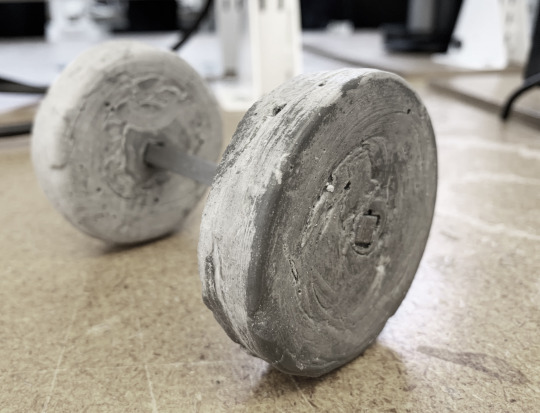
It was our team’s goal to store as much potential energy as possible to help our car fly across the table. We began the process of exploring how to store energy with torsion springs cut from delrin but we quickly made the jump to cast concrete (Rockite).
The torsion springs seemed to break no matter how we designed them to bend (plastic is inherently brittle). We focused our attention on flywheels which we decide to cast with Rockite to allow for the greatest amount of customization. Our first flywheels only measured 2.5″ in diameter. The image shown above was 6″ across because we calculated that the mass is important, but the larger diameter is more important.

We concluded that the two 6″ flywheels were massive but they put a lot of strain on the car’s axles. There was also too much friction at all of the joints were the gears, flywheels, and wheels met the axles. No matter how much potential energy is stored, the car’s mechanics have to be efficient or else the car simple will not move. The wheels should be able to spin for multiple seconds with a simple flick of a finger, and if they don't, your car will only move with a big push.
One final idea that was proposed that I wish we could have explored was the idea of rolling the car multiple times across the table to build up potential energy in the flywheel and then setting it on the table top to let the flywheel spin freely for multiple seconds and propel the car forward.
1 note
·
View note
Text
Watergate - Binary Adding Machine
Final Watergate Prototype - Assignment 3 (Alaa + Matt + Stephen)
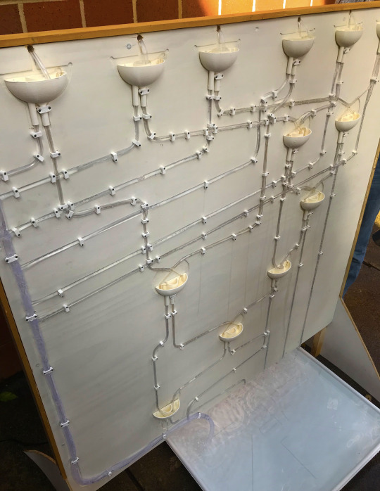
Our final binary adding machine using water is seen here. The system is comprised of a few main parts. The CNC routed pathway board, tube piping, polyester string, our 3D printed half adder design and water!
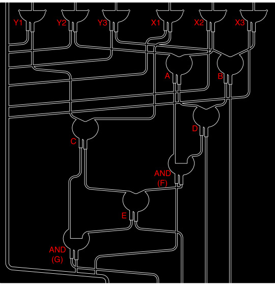
The idea for our full adding machine consists of the pathway shown above. We have six inputs at the top for the number selection. These inputs feed into two sets of 3 logic gates, labeled “Y1-Y3″ & “X1-X3″. The flow of information moves through the system and depending on the path through the watergates, the outcome will arrive at one of the four outputs at the bottom of the system. Not shown in the diagram above, is the flat bin at the bottom, the reservoir at the top that holds the water, and the water pump. These components act as a stabilization factor in our design that allows a continuous flow of water and input through our system. As the water moves through the adding system, the water is then recycled by the pump and continues the process again.
youtube
youtube
Our final design did come with some issues. The transfer of information at the gates proved to be a bit faulty at times. The string and the piping sometimes would not line up exactly which would effect the intended output from that gate. So the information relayed into the next step of the adder would then be incorrect causing wrong outputs at the bottom of the system. The miscommunication in this area of the system was our biggest complication in our final design. Assuming we did this project again, we would try to really work out the problems at the connection points in the system so that the relay of information was correct each time the system ran. Overall we had success in showing how our system can take multiple inputs and create a desired output.
#alaa+matt+stephen#watergate#half-adder#full-adder#binary#binaryaddingmachine#connectiveenvironments#assignment 3
0 notes
Text
Watergate - AND & XOR Progress
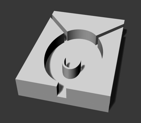
Through our process we have had to modify our concept multiple times. Above is our latest half adder. The concept allows for the AND & XOR gates to function together in one design.
We tested the 3D printed design and we found that the water flowed through each gate but it wasn’t as efficient as we would like. We had to modify the design to help direct the water so we added the plexiglass ramps to increase the speed of the water flow and we also moved the ramps closer to middle. WE found the water was still difficult to control, so we finally added the string to allow the surface tension of the water to carry it past the AND gate. Below are our test videos.
youtube
youtube
1 note
·
View note
Text
WATERGATE

Above is our groups first attempt at designing our AND, OR & NAND gates. Our design idea evolved from an attempt to mimic the Turing Tumbler design with with a quarter instead of a ball, to this. A water operating design with water being our input object. Our water gate design is explained further below.
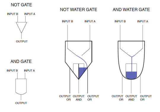
The design is meant to function by combining multiple gates into one piece. As you can see in the diagrams, the AND & OR gates are shown. The other part of the design not shown, are the straws. The straws would allow the flow of water to enter the system. This water flow would be our input. If you had a single input (a stream of water on one side), you would receive the opposite OR output. Same if the input was reversed. Assuming both inputs had water flowing our initial hope was that this would create an AND output. This output would be created by the flows meeting in the middle and creating a new output stream of water that would run down the middle through the AND output.

After a few trials, we found this AND output proved to be more difficult to control then we originally expected. A video below shows our attempt to manually control the straws and inputs.
youtube
0 notes
Text
Assignment 3 - Relay Attempt 1

Our group’s first idea was to try to incorporate a way of counting money using a binary system. We used the Turing Tumble design as our influence for this relay. Our first 3D printed relay is shown above. We sized the receiver to fit a typical quarter.
Below are our first sketches of trying to understand how simple change counter machines worked. We wanted to narrow down the change that we would use to a quarter. We then focused on how we could incorporate the Turing Tumble method with a quarter instead of a ball.


We wanted to have this relay piece attached to a board. The idea was that once you dropped a few quarters they would move through the system like the Turing Tumble machine. Our vision was that this design would count how many quarters you dropped through the machine.

0 notes
Text
The Good, The Bad & The Ugly: Assignment 2 Recap

Im going to start this blog by saying: YOU WILL FAIL! But with enough dedication, commitment and a ton of trial and error, YOU WILL SUCCEED and it will feel amazinggg!!!
youtube
Choose one LaserCutter and Stick to it!
Each machine will have its own tolerances, and it is unsafe to assume that testing results for one machine applies to the rest. The best recommendation for perfecting your craft is selecting one laser cutter and testing different material settings until you arrive at the best possible outcomes that result in the best possible fitting of pieces. I made the mistake of moving from one machine to another too many times which caused me to have to spend valuable time figuring out the best settings for that new machine instead of spending that time on improving the design.

Prototype early!
The absolute best advise anyone could ever give is to start testing models and gear ratios EARLY in the process (As early as the day you are handed the assignment). Our team went through three iterations of the design before we were able to arrive at a design that was elegant and (somewhat) functional.

Figure out your snap joints early!
Snap joints is what you are most likely to use to hold the car together. Because dealing with these kinds of connections is detrimental for the sturdiness and stability of your project, we recommend testing the snap joints simultaneously while testing laser cutter settings and material properties.

Casting Rockite: Fly-Wheel Designs Only
Casting the flywheels out of Rockite was no easy task. The goal with the flywheel design is to get the most inertia possible with the least weight necessary. To achieve such desired outcome, I recommend casting the heavy rockite the furthest distance possible form the axis of rotation. Bulky material closer to the axis of rotation of the flywheel will add to the overall weight of the car without adding significant inertia i.e. energy storage to the system. All this extra weight will cause your car to move slower and for a shorter distance, as well as increase the friction between its moving parts.

Make it the lightest possible!
After arriving at a design that seems to functions, I recommend taking one last pass at the design but this time carving out any material that is not serving a purpose. You can achieve that by hollowing out parts of the chassis that exist between joints as long as it does not interfere with the structural integrity of the car. As mentioned before, Flywheels can be reduced in weight by adding material close to the circumference of the circle and away from the axis of rotation.

Make your Drive Axle hefty!
This is something we realized after the fact; since speed in the flywheel is being transferred through the gears and transformed into torque in the drive axle, it is important for the drive axel to the consist of material that can tolerate such high torque. Because of that, it is recommended that you beef-up the drive axel in order to increase sturdiness and stability.

Final Remarks!
This assignment was a great challenge and an awesome learning experience all at the same time. In architecture, we are used to dealing with tolerances down to the 1/32″, which you may think is small but it is actually not. this Architectural-Engineering exercise made us think about functionality as a variable depended on tolerances that went down to the 10th of a millimeter. This exercise was extremely eyeopening in that regard, and resulted in products we were all proud of.
0 notes
Text
Assignment 2 - Outcomes & Reflection

Assignment 2 proved to be a challenging test of trial and error. Each prototype was constructed based on previous prototype attempts. Each process allowed for us to learn from each subsequent attempt. During each test run, we learned about the type of material, the different material thicknesses, connection techniques, construction techniques, and tension issues. This assignment proved to be a demanding one but each step allowed for a learning experience.
0 notes
Text
Second Prototype - Torque Test
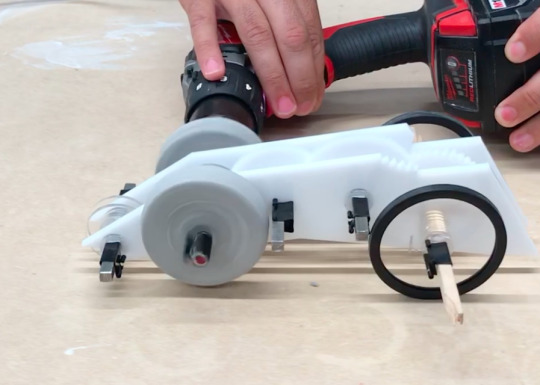
Once we completed our second prototype and the corresponding fly wheels. We wanted to test out the torque by using a handheld hammer drill.
Below are a couple videos showing how our second prototype functioned under +/- 800 RPMs by using the handheld hammer drill. These tests allowed us to understand how the gears and the fly wheels worked together.
youtube
youtube
0 notes
Text
Chassis Assembly Process & Challenges - Week 2

During the second week, we ran into some challenges attempting to make snap-fit connections on our chassis frame. The goal of this exercise was to design, create and test the snap-fit connections using acrylic and delrin.

Above are two attempts at designing and laser cutting the snap-fit prototypes. As you can see, the attempt on the left is much thinner and proved to work as well as the one on the right. We moved forward with implementing the snap-fit on the right into our chassis frames.

We first cut these chassis frame pieces out of acrylic to test the durability.

The photo above shows how some on the teeth on the snap-fit joints broken off. This form is what the frame would have looked like if the snap-fit connections had worked.

The second attempt we cut our the chassis frame pieces using delrin. We assumed the delrin would allow for some flexibility on the snap-fit connections. As you can see in the photo above this is what the frame would have looked like if the snap-fit connections had worked.

Ultimately the snap-fit connections on both the acrylic and the delrin failed.
0 notes
Text
Flywheel Car -progress week 3-
youtube
After creating the first prototype, we realized that an integrative assembly process where multiple subassemblies structurally rely on each other was harder to achieve than a lateral approach where each subassembly was connected to the other with the least amount of dependencies.
We were still having issues with connecting the chassis together separate from the axles since the rotation of the axles had to be independent from the chassis in certain instances but reliant on the rotations of the gears in other instances.
Our gear ratio for the first prototype was 1:6 which is exceptionally low. After testing this prototype, we discovered that a 1:6 gear ratio does not provide enough torque for the wheels to spin which resulted in the gears stopping as soon as the wheels touch the ground.


With the second prototype, and as a reaction to our first failure, we attempted to design a gear ration that was extremely high. For this design, we arrived at a gear ratio of 1:24 which provided a lot of torque to the wheels but was making the drive axle rotate at a very slow rate. For every 24 rotations of the flywheel, the wheels where completing only 1 full rotation which was causing the car to move barely and slowly.


Our findings proved that the best design is a design that balances speed and torque with a gear ratio in a range between 1:12 - 1:16. With the final prototype, we are exploring a 1:14 gear ratio that will hopefully propel the car forward with just enough torque and speed.
0 notes
Text
Flywheel Car -progress week 2-

The process of configuring and assembling a fully functional acrylic toy car that is powered by a flywheel has been quite the challenge.
We began by testing material in order to find the ultimate laser settings that will result in the best possible cuts.

The above settings appear to be the best for achieving clean cuts and not burning material. We quickly realized that having the laser setting at 100% power was causing the laser cone to cut wider at the top surface of the material versus the bottom surface. Fixing this issue required decreasing the laser power, increasing the speed and running the cut file twice.

The desired cut results was achieved after several attempts. This resulted in the fabrication of parts that cause the least amount of friction when in contact.

Flywheel cast in acrylic mold. Attempt failed because Rockite was not mixed properly and axle cast slightly of center.

Rockite reusable mold allows multiple testing of flywheel methods. Using binder clips to hold the mold together facilitated the disassembly of the mold to removed cast flywheels.

Testing different methods of clipping to attach acrylic chassis. Findings from these experiments showed that Delrin plastic is almost as brittle as regular acrylic.


0 notes
Photo


To fulfill the goal of making a car that can store energy and utilize that energy to move, our group decided to make a flywheel as the energy storage device. We cut a plexiglass formwork with a laser cutter and used Rockite and quick set cement as wheel material. Below are images of the iterations. The flywheel test required 4 iterations to perfect the Rockite consistency, the formwork construction, and the axle braces. The next step is to install the flywheel on the car chassis to test its ability to store potential energy.
#assignment_2 #alaa+matt+stephen #unccsoa #pullbackcar
0 notes
Text
Assignment 3: Water Binary Adder: Process/Reflection
youtube
Approaching the task to create a binary adding machine is was extremely overwhelming... But throughout the process, we learned alot about how to manifest conceptual systems into applicable scenario in order to achieve measurable results. The tick was to accurately construct each water logic gate and delicately connect it to the following gate otherwise, a small issue in the beginning exponentially grows into a bigger problem as the water is propagating through the system.
Beginning with testing individual gates, it was hard enough to control the flow of water from one gate to the other in a simple 2-gate assembly. As we conducted tests, we rapidly came to the realization that water was flowing inconsistently and that it would be incredibly difficult to create an open-loop system where water is released from the top and merely collected at the bottom. such system would mean that water would have to exit the tubes at EXACTLY the same instance and collide at EXACTLY the same force in order to combine and go through the AND gate. Also, learning from previous lessons and mistakes that students have made in the past, it became obvious that designing such a system becomes an issue of calculating speed of water and the distance it has to travel in the tube in order to achieve the correct outcome.
After thorough consideration, we were able to arrive at a solution that takes away the necessity of having simultaneous exiting of water by creating a closed-loop system that has water continuously flowing through it. Such system self corrects and reaches a state of equilibrium after a certain amount of time. Imaging water being pumped from a container at the bottom and that same water runs through the binary adding machine and is released in that same container. This closed-loop design allowed us to focus our attention on crafting the best water gate instead of spending hours matching waterline distances.
If water is coming out of one end only when it is supposed to be coming out of 2 ends for the binary addition to occur, the pumped water will eventually reach the second tube and flow out and into the AND gate.

Final prototype assembly in action


Crafting the final prototype required thinking about the overall look of the binary adding machine and not only its function. Because of that, we chose to move forward with a design that was intuitively diagrammatic in nature where the gates were laid out based on a “half-adder” scheme. Since the distances between gate inputs and outputs was no longer an issue due to the closed-loop system, we were able to map the vinyl tubing on the board in such a way that told a story about how binary mechanical adding works.
Seeing the system run became a lesson of how a half-adder adds the binary inputs and how a carry bit is outputted as information from one half-adder into the next AND gate connecting the half-adders into a full adding system.


youtube
youtube
youtube


#alaa+matt+stephen#assignment 3#alaaboughanem#binaryaddingmachine#watergate#waterbinaryadder#assignment 3 reflection#reflection#watergate reflection
0 notes
Text

The Watergate contraption is the illustration of computation in its simplest form. The construction is a binary full adder, but the intention is to comprehend how computing can be interactive and visible. The techniques expressed in the Watergate Project could be scaled up to represent how utilities and infrastructure could be reimagined as a computing mechanism and public art display. Computers and infrastructure are similar because the information systems are hidden behind screens or in boxes and the life giving systems are hidden under streets or in walls. The act of deconstructing these systems to occupy public space would provide an experience where computing would become intuitive and appreciated. Large scale construction projects and high water table in Berlin require infrastructure to be temporarily located above ground where water flows in large steel pipes share the public space with the flows of transportation. What would a world look like if the flows of information, infrastructure, and transportation all shared public space and computation was as intuitive as redirecting the flow of water to compute binary addition?
#alaa+matt+stephen#watergate#half-adder#full-adder#connectiveenvironments#binaryaddingmachine#assingment3
0 notes