#connectiveenvironments
Explore tagged Tumblr posts
Visit Tumblr Blog
Explore Tumblr blogs with no restrictions, modern design and the best experience.
Last Seen Tumblr Blogs


Fun Fact
There are dozens of funny blogs to kill time on Tumblr.
Text
Magnet Binary Adding Machine

Our efforts to design a magnetically based binary adding machine have resulted in this system. Compromised of several modular parts, this whole system is actually a number of individual pieces that when used in conjunction, create the workings of a complete half adder. When run through the system multiple times, one can continuously add binary digits, therefore working as a full adder.

Its important to note how we coded these pods. A vertical pod can be read as a “1″ and a horizontal can be read as a “0″. In prior experiments, we had coded magnetic polarity as either a one or a zero (North side being “1″ and South side being “0″), but labeling them as such gave us limited options. Namely, this only resulted in a natural XOR gate. This made it extremely difficult to develop any other system than this.
In order to accomplish a new method of inputs and outputs, we used two forms of magnet pods. The first one (on the left side) functions as the initial input. These are fixed values, incapable of rotating around within their housing. The second (on the right) can spin, thus rotating itself into the proper orientation.

When the rotating output pod leaves the gate, it is lock in place using piece like the one pictured. This allows the output pod to work in the same fashion as the initial fixed inputs.
youtube
The AND gate is our simplest mechanism. Two inputs placed on the outside slides control the orientation of a single magnet. Every placement of the input except a “1″ and “1″ result in a “0″. The is due to the proximity of the horizontal “0″ input. Because it is closer to the rotating output pod, the output pod rotates closer to the horizontal.
youtube
Our XOR and OR gates function as identical mechanisms with very small differences in their locking mechanisms.
Our gates would sometimes result in undesirable outputs, namely 45 degree angles. This was an issue, since we can only work in horizontal and vertical variables. In order to solve this, each gate was given a different locking mechanism for its output pod.
These output mechanisms had extending arms that, when entered into the second stage of the gate, would push out either a fixed “1″ or “0″ pod.
In essence, if the output pod is rotated at a 45 degree angle, the arm is as well, therefore bypassing the adjacent output arm and directly coming into contact with the opposing output.
Our system did not come with out issues. Although we were able to work out some of the larger problems of polarity (and magnetism in general). Our system lacks an infrastructure to clearly denote and mark the path of the outputs. Perhaps a railing system could be of some use in the next draft.
Its hard to avoid the fact that our locking arm solution was more of a fix for an existing problem rather than a cohesive part of the system. It was, in fact, a method proposed to resolve an undesirable outcome that happened to be in inherent issue of our machine.
E+R
#Magnetic Binary adder#Binary adding machine#connectiveenvironments#assignment_3#magnets are cool#magnets
2 notes
·
View notes
Text
Watergate Reflection

The Watergate contraption is the illustration of computation in its simplest form. The construction is a binary full adder, but the intention is to comprehend how computing can be interactive and visible. The techniques expressed in the Watergate Project could be scaled up to represent how utilities and infrastructure could be reimagined as a computing mechanism and public art display. Computers and infrastructure are similar because the information systems are hidden behind screens or in boxes and the life giving systems are hidden under streets or in walls. The act of deconstructing these systems to occupy public space would provide an experience where computing would become intuitive and appreciated. Large scale construction projects and high water table in Berlin require infrastructure to be temporarily located above ground where water flows in large steel pipes share the public space with the flows of transportation. What would a world look like if the flows of information, infrastructure, and transportation all shared public space and computation was as intuitive as redirecting the flow of water to compute binary addition?
1 note
·
View note
Text
Assignment 2 - Outcomes & Reflection

Assignment 2 proved to be a challenging test of trial and error. Each prototype was constructed based on previous prototype attempts. Each process allowed for us to learn from each subsequent attempt. During each test run, we learned about the type of material, the different material thicknesses, connection techniques, construction techniques, and tension issues. This assignment proved to be a demanding one but each step allowed for a learning experience.
1 note
·
View note
Text
Magnetic Logic Gate Update
We are looking for solutions and new ideas to combine multiple gates and magnets to create the desired outputs.
After receiving comments on the repeatability and ability of our half adder to carry the digit to the next system of adding we explored with other systems and methods.
The idea that was suggested in review was to have some kind of rotational movement done by diametrically polarized spherical magnets.

First we tried to set up a system where the magnetic marbles to rotate in between two planes where they would be held tightly. The problem that arose was from the distances between the magnets and the indication of them rotating and them snapping together was too quick. The rotational movement of one ball was not a effective way of relaying information.

We tried to draw out geometic ways to combine three magnets in a way that would produce a consistent result.


More diagrams of combining multible spheres to create consistent results or any type of gate. Magnets really only are good at creating XOR gates and srtuggle with any other gate.

We also thought about combining the rotational move of the spheres with the bars from the previous prototype.

We then tried to construct prototypes to test this idea with cardboard and two 15mm spherical magnets and the results were informative. The groups of two magnets show the polarization better than a single magnet, so we used the set of two. It works great when there are only two groups of two magnets next to each other, but we need a system that has two inputs and one output. When we used three groups of two magnets the magnetic pull of each magnet was not as a direct correlation to what was a 1 or a 0 or any directionality at all.
youtube
youtube
0 notes
Text
Loads of Potential

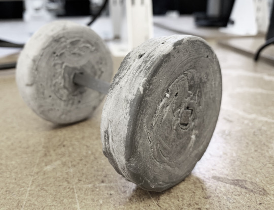
It was our team’s goal to store as much potential energy as possible to help our car fly across the table. We began the process of exploring how to store energy with torsion springs cut from delrin but we quickly made the jump to cast concrete (Rockite).
The torsion springs seemed to break no matter how we designed them to bend (plastic is inherently brittle). We focused our attention on flywheels which we decide to cast with Rockite to allow for the greatest amount of customization. Our first flywheels only measured 2.5″ in diameter. The image shown above was 6″ across because we calculated that the mass is important, but the larger diameter is more important.

We concluded that the two 6″ flywheels were massive but they put a lot of strain on the car’s axles. There was also too much friction at all of the joints were the gears, flywheels, and wheels met the axles. No matter how much potential energy is stored, the car’s mechanics have to be efficient or else the car simple will not move. The wheels should be able to spin for multiple seconds with a simple flick of a finger, and if they don't, your car will only move with a big push.
One final idea that was proposed that I wish we could have explored was the idea of rolling the car multiple times across the table to build up potential energy in the flywheel and then setting it on the table top to let the flywheel spin freely for multiple seconds and propel the car forward.
1 note
·
View note
Text
Oscilloscopes - Conception of the Idea

When exploring methods of facilitating interaction between two people, we knew we wanted to use both audio and visual media to represent an abstraction of human conversation. We tossed around some ideas for games involving an audio sensor. But, upon further research into audio-visual media, we discovered a handful of installations that were using oscilloscopes as a means to represent music through visualized sound waves.
Artists such as Andrew Duff use analog synthesizers to control the X, Y, and Z axis of an oscilloscope. Each axis has a unique sine-wave input, the culmination of these inputs results in a 3D composition comprised of each sine wave. As the sine waves begin to modulate, so does the image. Below are a series of visual pieces Duff has created with his oscilloscope.


Heavily inspired by this piece, we began thinking of ways we could use the human voice to create a visual composition between two individuals. By using just the X and Y inputs, each voice could control one axis, effectively rendering the interaction of two human voices as a single visual abstraction.

Luckily, old CRT televisions from the 1990’s use very similar technology to an oscilloscope. We can modify these televisions to control the X and Y coordinates of their screens using audio inputs such as microphones, instruments, or anything else that produces noise. The ultimate goal is to create an interface for two individuals to use their own voices to create a collaborative composition, thus facilitating human interaction through their own vocal cords.

Below is a link to Andrew Duff’s live show. Watch a few minutes of it to see these visual pieces become animated, and also see how they relate to the audio signal.
youtube
1 note
·
View note
Text
Vocal Visuals: audio and visual telepresence
Eliot Ball and Ricky Young
We bring to you our finding and studies of how a pair of people interact through a point in an axis controlled by the sounds they make.
And talk about the final advances that brought us to a point where we could test this project.
Stereo Amplification and Dual Screen Routing
The stereo amplifier that we purchased (the LEPY 2020A) was key to the success of the oscilloscope system. Prior to purchasing an amplifier, the waveform was so small the display appeared as simply a quivering line on each axis. The amplifier increased the amplitude of the signal enough to provide each axis with a waveform capable of taking up the entire screen. In addition to this, the amplifier came with a built in voltage transformer. It seems as though this transformer as provided the coil within the television with the proper amount of signal, therefore solving the problem that plagued many of our previous iterations. Because the television was being fed the proper amount of voltage, the system didn’t fail or automatically should down.
With the issue of the television and waveform displays solved, we moved on to the problem of how to make this installation into a dual screen set up. We took advantage of some home studio equipment we had available. Using an audio interface (a Focusrite Scarlett 18i20), we were capable of developing a series of routing paths that would split input signals, meaning each microphone could be sent to multiple sets up televisions at once (up to 8 in fact.) We then purchased a specialty microphone cable that converted a standard XLR jack into a stereo RCA output. Each stereo amplifier requires a stereo RCA input, so this cable was paramount in transferring the standard microphone jack into something capable of being received by the amplifiers.
Within the audio interface’s software, we assigned these specialty microphone cable as outputs 1+2, and a monitor speaker for each TV as outputs 3+4. We then instructed each microphone signal to be sent to their corresponding specialty cables, as well as sending each microphone to the speakers. Because the specialty cable resulted in a stereo RCA jack, we then routed ONE of each stereo pair to either amplifier. The resultant signal path gave each television a display of both microphone inputs.

a diagram showing the wire we used to split the XLR audio signal from the microphone into left and right RCA signals.

diagram of the full system with pictures of each element
User Studies and Results
With all systems solved and ready for installation, we ran a series of user studies in order to observe how participants would interact with the interface. We specifically wanted to see how a diluted sense of each other’s presence might affect a user’s interaction with the opposite person. Would such a scenario enhance two strangers attachment do one another? What might occur when two people familiar with one another? We wanted to see what trends we could observe based upon the relationships of the two people, and also see how much cooperation was fostering through interacting with the interface.
In addition to letting the two participants hear both of their voices while speaking, we also engaged in an alternative version of the experiment that prohibited the users from hearing one another. This involving cutting the microphone input to the speaker, pumping white noise to each user, and giving each person a pair of ear plugs. We observed the differences between a purely visual stimulus and one with both audio and visual cues.
While the studies were occurring we also recorded each interaction on both microphones and with a video camera on each participant. With the recordings handy, we can pump the original audio back through the interface, effectively creating a simulation of their initial dialogue.
After each pair finished their session, we gave them each a questionnaire in order to gauge their reaction to the experiment. The questions focused on their own feelings during their experiment, their engagement and connection to their partner, and also if they felt the interface enabled or inhibited a meaningful interaction.
Discussion of Results
After observing and recording the user studies, we began to notice several trends develop within the experiments. Many reacted positively to their partners role in the interaction. Each group had a different dynamic, but in general pairs (who often did not know each other prior to the installation) would sing together, hum together, or make wacky noises together. They observed the visual output of their voices, augmenting the sounds they made to play with the shapes that appeared on scream. Some would coordinate efforts, each producing a different noise to facilitate a unique shape. Others attempted to match notes in order to make a “perfect circle” or to at least make the waveform stand still for a brief moment.
There was a minority of participants who seemed to feel mildly uncomfortable with the experience, choosing to talk in short bursts and observe their individual axes move horizontally or vertically, never fully giving themselves to the interface. Yet it should be noted that there was never any disinterest. Those who felt uneasy engaging with their partner still interacted with the interface and expressed enjoyment in the outcome. Still others began to engage before laughing too hard to continue, not an ideal but still very satisfying outcome.
In general, observing one's partner through the abstracted lens of diluted physical presence, meaning a distillation of an individual into merely one or two perceptible variables, seems to have an effect on the user's inhibitions and sense of humility. In a way the installation acting as an ice-breaker of sorts. Here are some quotes from the questionnaire that reinforce that notion:
What effect did the interface have on two strangers interacting with one another?
“I could communicate with someone that I didn’t know through something that I wasn’t familiar with, but it was actually working.”
“It was just an instant moment of collaboration.”
“I feel as if I went on a blind date spontaneously, the TV allows for a level of intimacy that you might not have ever expected with the person you’re doing the experiment with.”
“I didn’t know my partner, but the oscilloscope allowed us to have fun together and be silly in a way that we wouldn’t have been able to without the oscilloscope.”
How did the interface contribute to the interaction with the other user?
“Well, it was the limitation of interaction that really defined the connection.”
“Took away the human element. It felt like the future of communication.”
“It was kind of like a battle to see who could get the longest or highest line between the two of us. But it was cool to see the mix of the same pitch and volume.”
“It made me question his intentions or emotions.”
“Technology typically doesn’t require more than one person to activate, so the act of collaboration makes more a dependence we tend not to expect/encounter.”
Further studies will continue using these oscilloscopes. More intense scrutiny regarding participants relationships to one another will further develop and uncover trends of human interaction and meaningful connection. Though in general we are very happy with the methods in which people cooperated and created together, forming small visual artifacts that are quite literally a composition of their combined efforts. More work to come, stay tuned.
0 notes
Text
Connective Compasses: (Telepresence Through Tactile Representations of Orientation and Distance) Final Reflection
youtube
In Assignment 4-5, we developed a prototype for a pair of connected compasses as an alternative way for two humans to understand each other’s geographical direction through haptic feedback. These Connective Compasses allow for two people, who are separated by a specific distance, to recognize each other’s direction through haptic feedback. Similar to a compass, the orientation of the instrument is critical. Assuming there are two people apart from one another, these compasses explain the opposite person’s position tactilely. As each user attempts to locate each other, vibration cues are provided as output feedback to inform and identify their direction. The haptic responses felt on the compasses are designed to emit this vibration feedback until the person is pointing at the other. Once the user’s orientation is located the compass switches to a neutral state, ultimately explaining the other users’s direction.

The connective compass ignores typical visual feedback describing a person’s direction. Alternatively, providing vibration patterns or cues as the tactile feedback to explain the person’s orientation.
During our design process we worked with 2 of each of the following parts as we built our prototype. SparkFun 6 Degrees of Freedom Breakout - LSM303C, SparkFun GPS Breakout - Chip Antenna, SAM-M8Q (Qwiic), Vibration Motor, SparkFun Haptic Motor Driver - DRV2605L, ELEGOO 170 tie-Points Mini Breadboard kit for Arduino, MELIFE 2 Pack ESP32 - ESP-32S Development Board, & Insignia - 5000 mAh Portable Charger. Which ultimately led us to the final wiring design shown in the Fritzing Diagram below.

The next process included designing an enclosure that would efficiently house the electronics and the wiring shown above. We worked through this process with more of an efficiency approach than a aesthetically pleasing one. This allowed for the following our first compass prototype. See an exploded axonometric drawing below describing our first iteration of the compass. Moving forward we will work to refine this design so that the materiality and the

Future work would first focus on further refinement of the compass’ design. During our initial design process we were more concentrated on the technical components and assembly, which ultimately drove our physical design. As the design continues to develop, we would need to ask ourselves the following questions; how doest his compass feel?; what is the materiality of the compass?; what is the ideal size of this object?. Furthermore, we must consider the emotional factors as we refine our design. These decisions will be beneficial to how potential users experience and interact with the compasses.
Additionally we may consider incorporating user tests with our compasses. In these user studies we would need to consider testing three different group; two companions, two friends, and two strangers. The feedback form these types of users would allow for us to determine how successful each group interacted with the compasses. Observing the results from the tests would allow us to identity which areas in design we would need to focus on refining.
Another factor we could consider testing is the physical location of where the user tests are based. Since the compasses focus on orientation of a person, it would be interesting to see how users react when tested at varying geographical distances. One test could be done at a small scale on a campus while the other test could be done at a larger scale in a city.
In the final analysis of the user tests we could understand how different relationships and places from one another affected the users interaction with our design.
0 notes
Text
The Hills and Mountains of the Oscilloscope
Eliot Ball and Ricky Young
There were many problems and issues we faced when trying to make an oscilloscope, but all was not in vain, as a functioning oscilloscope has been produced. (see below)
In order to create an oscilloscope from an old CRT TV we must understand CRT TVs. The thing we are after is the electron ray (figure 1) and the deflection coils (figure 2). Normally the TV would send electronic information to the deflection coils that pull on the electron ray as it shoots towards the screen, mapping each pixel. In our case, we want to take the wires that would transmit the location information of the pixel and wire them instead to audio signals coming from various places, like microphones, synths, or music. The result should be the waveforms created by the music visualised on the screen of the TVs.

fig. 1

fig. 2
fig. 3
To start this process we bought two tvs off of craigslist and immediately ripped them apart and cut up their insides! After sifting through a bunch of youtube channels, we found a way to discharge the TV with a wire and a screwdriver(figure 3). To discharge the CRT TV we needed to attach the wire to ground and the screwdriver to ground port at the top of the cathode ray tube(figure 4). We needed to ground the TVs before touching any of the fun stuff inside, for the first time we did this very tentatively, scared of the 20,000 volts the cathode ray could hold!!! After a couple successful attempts we felt more comfortable and were able to start the oscilloscope making process.

fig. 4
We cut the four wires, tested their continuity to see what wires were connected, and soldered them to the left and right of a ¼” audio inputs. For the first test we turned it on without connecting it to any signals, our goal here was to achieve a dot in the middle of the screen. And the tv turned on and gave us the dot but it was very small, so we decided to adjust the screen knob in the back of the TV to turn up the amount of light produced by the electron beam. Turns out (haha) turning the screen knob while the TV is on changes the voltage through the system and fries the flyback transformer (figure 5). So the first TV we tested died the day she joined the team RIP: Abigail.

fig.5
Note: we named all the TVs in alphabetical order to keep track and to give them some support when they need it or for funerals. So A=Abigail B= Betsy and so forth…
The next TV we tested was a newer smaller TV named Betsy. She was more promising so when we soldered the ¼” audio input, it produced a point in the middle. But Betsy was strange. We started to input audio with a synth and she began by responding very slightly to the notes on the synth. As we continued, she outputted a high pitch sound that started to play over the synth. The light in the middle got brighter and brighter, the sound from the TV got louder and the sounds from the synth got softer and softer. Then something really weird happened, the synth stopped outputting different notes, only the high pitch noise that the TV made, even after we unplugged it from the TV the keyboard would only make one sound at one volume. So we stopped using Betsy and gave the synth a couple days rest.
So we need more TVs and a better method. We called around and turns out many people wanted to get rid of their old CRT TVs, so with a little organizing, two cars, and three sets of arms, we picked up 6 more TV in one day. We also got some speaker that would relay signals and protect any input source and allow us to hook up the wires directly from a phone or computer.
In the subsequent test on Carter and Darrel ran into similar issues. A problem we ran into was to do with the year the TVs were made. Basically there is some kind of safety mechanism in the TVs from 2000 on that reads the voltage going from the motherboard to the electron ray that will shut off the electron beam if there is a difference in voltages between the sides of the coils. So we only found this out after having the TV work until we tried to change their inputs. We could produce a horizontal line (cutting vertical deflection coil wires) and a vertical line (cutting horizontal deflection coil wires), but as soon as we put any signal through the cut wires the TVs would power off.

Horizontal beam created on Eddie (the fuzz around the bottom of the line is the created from the audio signal

Vertical beam created on Eddie
The first signs of success we had was with the fifth TV, Eddie, an older TV without care for annoying safety mechanism. We were able to use an audio interface to wire signals to one of the directions in the TV. But the only thing we were able to produce was small variations in either direction with the sound that we had. But as the signal continued, the beam seemed to split and made a similar high pitched to Abigail and Carter. The next day when we brought it to class to show off our success, it failed to even turn on, so it probably died some time after the previous nights tests.
The last thing we changed was the audio interface, LEPY, that had two inputs for microphones, two left and right outputs for a speaker system, and a voltage adapter. We also tested on some of the older TV, Fritz and Gertrude, but we did the same process as all the TV beforehand and able to finally achieve the oscilloscope goal!!! And we tried it on some willing participants that had fun with the interface!
youtube
youtube
youtube
0 notes
Text
Assignment 4: Progress - The Compass Connection

This week Nicholas was able to get the SparkFun 6 Degrees of Freedom Breakout - LSM303C connected to the system. This part is comprised of an accelerometer and magnetometer to be able to identify the four cardinal directions, north, east, south, and west.
This is important because one of the factors we want to identify is not just the GPS location but also the orientation. The north direction reads as “0.0″ and as you rotate the device clockwise 90 degrees the reading moves to “90.0″ to indicate the east direction. Here is a video showing the device working and the output data being displayed on the screen. These readings will be key as we work towards connecting the two devices later this week.
youtube
0 notes
Text
Assignment 4: Progress - The Compass Connection

For Assignment 4 (Connected Artifacts), Nicholas and I are focused on developing a pair of artifacts that act as compasses that have a direct relationship with each other. The goal is to have the two separate compasses be able to point and locate each from long distances apart. We envision that these compasses will act as a way of connecting two users that are apart from one another.

Once we received all of the materials and parts for our project we were tasked with modifying a socket.io web page that Dimitris had provided to us. We implemented the GPS coordinates from the SparkFun GPS Breakout - Chip Antenna, SAM-M8Q (Qwiic) to this socket.io web page.
youtube
0 notes
Text
Watergate - Binary Adding Machine
Final Watergate Prototype - Assignment 3 (Alaa + Matt + Stephen)
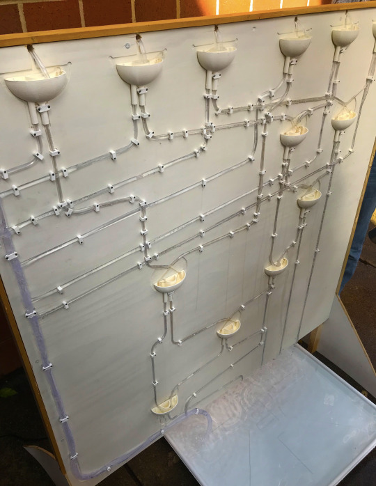
Our final binary adding machine using water is seen here. The system is comprised of a few main parts. The CNC routed pathway board, tube piping, polyester string, our 3D printed half adder design and water!
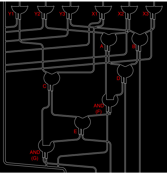
The idea for our full adding machine consists of the pathway shown above. We have six inputs at the top for the number selection. These inputs feed into two sets of 3 logic gates, labeled “Y1-Y3″ & “X1-X3″. The flow of information moves through the system and depending on the path through the watergates, the outcome will arrive at one of the four outputs at the bottom of the system. Not shown in the diagram above, is the flat bin at the bottom, the reservoir at the top that holds the water, and the water pump. These components act as a stabilization factor in our design that allows a continuous flow of water and input through our system. As the water moves through the adding system, the water is then recycled by the pump and continues the process again.
youtube
youtube
Our final design did come with some issues. The transfer of information at the gates proved to be a bit faulty at times. The string and the piping sometimes would not line up exactly which would effect the intended output from that gate. So the information relayed into the next step of the adder would then be incorrect causing wrong outputs at the bottom of the system. The miscommunication in this area of the system was our biggest complication in our final design. Assuming we did this project again, we would try to really work out the problems at the connection points in the system so that the relay of information was correct each time the system ran. Overall we had success in showing how our system can take multiple inputs and create a desired output.
#alaa+matt+stephen#watergate#half-adder#full-adder#binary#binaryaddingmachine#connectiveenvironments#assignment 3
0 notes
Text
Binary Adding Machine - A Reflection

Comprehending computation through the lens of physical and mechanical components is a fantastic way to understand the broader landscape of computation.
Computing can seem like a mysterious thing; something that occurs inside of a box, and beyond anything your eyes can comprehend. Designing a mechanical object not only allows you to visibly see each component at work, but also forces you to thoroughly grasp each concept so that you can fabricate a functional piece.
Working with magnets was hard, but extraordinarily helpful. Helpful because they come with a rule set. Unlike a marble, magnets come with predefined properties that force you to work within the constraints of their nature. This helped in some ways. For example, understanding binary logic and developing a clear definition for an output. But it also made things extremely difficult at times, namely when the magnets refused to adhere to a system that seemed to work in theory.
When attempting to design an adding machine, I would recommend working with a material like magnets. Not because it’ll be easy, it won’t be. Rather because working with mediums that already have an ingrained rule-set means that you do not have the freedom to design without borders. Mediums like this must inform you design, because if their properties are not allowed the ability to operate and exist then your system won’t either.

#Magnetism#Binary Adding MAchine#Magnetic Binary Adding Machine#Computation#Mechanical Computation#connectiveenvironments#UNCCSOA
0 notes
Text
ASSIGNMENT_03 : BINARY ADDING MACHINE
( RESEARCH // INSPIRATION )
( Christopher Meza + Nicholas Rowlings + Arghavan Ebrahimi)
Pneumatic Logic Elements.
youtube
The video is part of the “Only Paper” forum. It is a very detailed video that explains the way in which the relay and the mechanism works.
As part of our research we wanted to find any type of writing or prototypes, if there were any, that had been developed before. When we stumbled upon this work we began to understand the way the machine would work as a whole, but there were still limitations to how our work could further this research.

https://only-paper.ru/forum/38-23291-1
This is the link to a forum called “Only Paper”, Pneumatic Logic Elements.
Although the paper adding machine has provided us with large amount of content we felt as though we needed to add our own spin to the way the relays worked. We decided to move up to a larger scale because in order to fully automate the adding me machine we would need to use a constant source of pressurized air. At this scale, paper provided its own limitations, not only fabrication but also, again, in maintaining a fully pressurized system.

This picture depicts the fabrication of a paper relay that we developed in order to test the possibilities of a larger relay. (Very interested in the material properties that this assignment could lead us to explore). The paper relay follows the same language as the precedent we found, in terms of cutting and folding. Although not difficult, while the relay begins to take form in an origami like manner, it its clear that there is a higher level of precision required when considering components need to move within one another.

Making a reference to our early studies and research of pneumatic systems, this piece takes into consideration the need for exhaust apertures in order to let extra pressure escape before it could create a buildup that could in term cause damage to the relay. Similar tot he first model, this one is also assembled by cutting paper and folding tabs.
youtube
This is a video that demonstrates how the relay/inverter would work once there is an input. Very quickly we realized that indeed, we would need a higher psi in order to be able to operate a series of logic gates that would, combined, function as a full adding machine. Although the exhaust apertures worked, we also noticed that there was a large amount of air that was escaping around the shuttle moving inside the relay.

The image above is a diagram that depicts the way the paper relay would function. We can see that the air supply remains constant, (the need for en exhaust port is necessary to relieve pressure until the relay received the input and it allows the air supply flow to continue to move through the channel until it reaches the next relay or a logic gate. At that point the pressure would increase again, constantly exhausting air until the next input is applied.
0 notes
Text
Watergate - AND & XOR Progress

Through our process we have had to modify our concept multiple times. Above is our latest half adder. The concept allows for the AND & XOR gates to function together in one design.
We tested the 3D printed design and we found that the water flowed through each gate but it wasn’t as efficient as we would like. We had to modify the design to help direct the water so we added the plexiglass ramps to increase the speed of the water flow and we also moved the ramps closer to middle. WE found the water was still difficult to control, so we finally added the string to allow the surface tension of the water to carry it past the AND gate. Below are our test videos.
youtube
youtube
1 note
·
View note
Text
Magnetic Binary Addition Studies
After studying and modeling a precedent, we began to develop our own similar concept with the use of magnets.

This adding machine has two key elements: the ability to hold one sum bit in place as the carry bit enters the system, and the ability to simultaneously release the sum bit and move carry bit into the next stage. Its also a modular scheme, allowing us to replicate similar systems and pathways at each gate.

Our own version of this system was a very literal interpretation of the original. When a ball entered the system, it would transfer to the holding bay of the first stage. The second ball would enter the system, engaging a line of magnets, terminating at the two holding the original sum bit ball. This version was riddled with issues. Not only would the magnets likely stick and never undo themselves, but there was no way for the original ball to pass into the first stage without first activating the switch that would force it onto the carry bit’s pathway. On top of this, the use of gravity AND magnets as an energy source was redundant. The same system could be accomplished using strings.

We began sketching out concepts for a system that utilized magnets as the only energy source. We studied the motion of magnets along a set of predefined pathways as a method of relaying information from the input to an output. We used simple cardboard studies to accomplish this.
youtube
youtube
youtube
By considering the MOTION of the magnet as the definition of whether the information is a “0″ or a “1″, we could effectively use magnets as a means of addition. “1″ is defined as the movement of the carry bit outwards, and “0″ is defined as the carry bit rescinding inwards. This motion and consequently the numbers assignment to those motions can be transferred through the propelling of each magnet until it reaches the next gate, at which the process begins again in the new stage.
0 notes